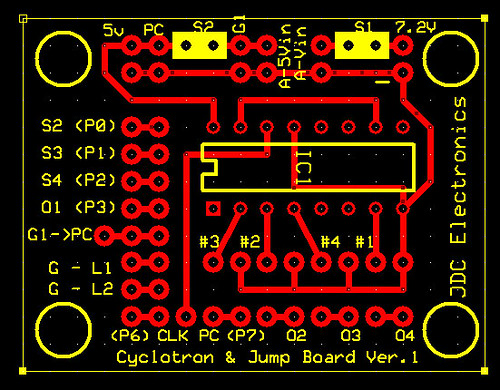
I’m not sure what it costs to etch a board, but www.batchpcb.com offers professionally done PCB etching on the cost of $2.50/square inch, with a $10 setup fee. From what I’ve read, the turnaround time is about a month, which isn’t bad.
I’m considering doing it myself to make a holder for my bargraph LEDs and shift registers, I’d really like to stay away from the rats nest of wires that my breadboard is right now.
I’ve laid out the boards and will have to double check layout/fitment before I start etching them. Will have to sort out proper documentation as the boards aren’t all matched up yet.
I’ve only done a little etching myself, and that was years ago, so I have no idea how much of an issue this is, but I’ve heard that having right angles in traces can trap acid in the corners when etching which might lead to them being broken. You may want to consider rounding the corners off.
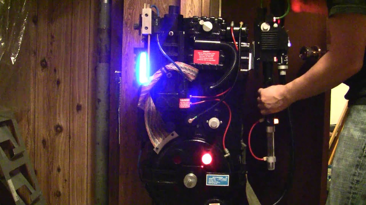
well pack is done. I made a 3 mistakes on my electronics but they were minor ( that’s what you get for rushing I guess). I laughed all through out the project because to me this is ridiculous. it’s done and I’m sad and happy all at once.
Here it is.
it will probably only see a few Halloweens then collect dust or stripped for parts. I can’t be a Ghostbuster EVERY Halloween
due to time constraints I didn’t create a schematic before creating the board. I might redo the electronics (and take my time) just for fun. that’s what this whole project was really about.
I can post PDF/original PDE files but I would only use this as a reference. I would already change a few things and do it differently. I just wanted to get this project done for Halloween.
I’ve implemented a similar circuit to yours. Don’t have gun lights and my cyclotron uses a 555 for timing so I pulled the relevant bits out of your code:
<i>
</i>//Pin connected to SH_CP of 74HC595 (pin 11)
int clockPin = 6;
//Pin connected to ST_CP of 74HC595 (pin 12)
int latchPin = 8;
////Pin connected to DS of 74HC595 (pin 14)
int dataPin = 7;

// saved vals
byte dataPWRCL;
byte dataPWRCL2;

// data arrays
byte daPWRCL[15];
byte daPWRCL2[15];

void setup() {
  //set pins to output so you can control the shift register
  pinMode(latchPin, OUTPUT);
  pinMode(clockPin, OUTPUT);
  pinMode(dataPin, OUTPUT);

  daPWRCL[0] = 0x00; //00000000
  daPWRCL[1] = 0x00; //00000000
  daPWRCL[2] = 0x00; //00000000
  daPWRCL[3] = 0x00; //00000000
  daPWRCL[4] = 0x00; //00000000
  daPWRCL[5] = 0x00; //00000000
  daPWRCL[6] = 0x00; //00000000
  daPWRCL[7] = 0x80; //10000000
  daPWRCL[8] = 0xC0; //11000000
  daPWRCL[9] = 0xE0; //11100000
  daPWRCL[10] = 0xF0; //11110000
  daPWRCL[11] = 0xF8; //11111000
  daPWRCL[12] = 0xFC; //11111000
  daPWRCL[13] = 0xFE; //11111100
  daPWRCL[14] = 0xFF; //11111100

  daPWRCL2[0] = 0x80; //10000000
  daPWRCL2[1] = 0xC0; //11000000
  daPWRCL2[2] = 0xE0; //11100000
  daPWRCL2[3] = 0xF0; //11110000
  daPWRCL2[4] = 0xF8; //11111000
  daPWRCL2[5] = 0xFC; //11111100
  daPWRCL2[6] = 0xFE; //11111110
  daPWRCL2[7] = 0xFF; //11111111
  daPWRCL2[8] = 0xFF; //11111111
  daPWRCL2[9] = 0xFF; //11111111
  daPWRCL2[10] = 0xFF; //11111111
  daPWRCL2[11] = 0xFF; //11111111
  daPWRCL2[12] = 0xFF; //11111111
  daPWRCL2[13] = 0xFF; //11111111
  daPWRCL2[14] = 0xFF; //11111111

}

void loop() {
  for (int ii = 1; ii < 15; ii++) {

    //load the light sequence you want from array
    dataPWRCL = daPWRCL[ii];
    dataPWRCL2 = daPWRCL2[ii];
    // take the latchPin low so
    // the LEDs don't change while you're sending in bits:
    digitalWrite(latchPin, LOW);
    // shift out the bits:
    shiftOut(dataPin, clockPin, MSBFIRST, dataPWRCL2);
    shiftOut(dataPin, clockPin, MSBFIRST, dataPWRCL);

    //take the latch pin high so the LEDs will light up:
    digitalWrite(latchPin, HIGH);
    // pause before next value:
    delay(50);
  }
}
I modified the pattern a little to remove the overlapping lights (two come on at at the same time). Have to sort out the audio stuff now but I don’t have an amp so it’s likely to be a bit redundant.
If it’s not too much trouble could I have a copy of your finalised code?
No worries. I figured you might have made some tweaks.
By the way, I want to say a massive thank you; I built my circuit on stripboard but your PCBs were invaluable in helping me to lay everything out. Your code was immensely informative too - I figured out the guts of the code from the Arduino tutorials but having purpose-written code is wonderful.
Couldn’t agree more with Martinus, absolutely wicked squire, THANK YOU!!
A couple of things I am missing though are as follows:
On the wand, there should be 3 toggle switches and 2 push buttons, correct? The toggle switches are at the main rear control panel with one push button for firing. The other push button is near the nozzle for playing/changing songs. In your code, I have only been able to find pin 14 to start the pack/light sequence (toggle switch), pin 15 to fire the wand (momentary push button) and pin 16 to play the songs (momentary push button). I assume another toggle switch would be between the battery and vin on the Arduino with only 2 white LEDs coming on with that switch, but what does the final toggle switch do and where should it be connected?
All the power cell lights, bar graph lights etc. go full on when i put power to the Arduino. As soon as I ground pin 14 on the Arduino (dip switch on the breadboard to “start up” the pack), the lights all cycle as normal. I’m trying to figure out what I skipped (or added) that may be causing this. In your youtube vid, you flip a switch and 2 white LEDs come on. Then you flip the next switch and all lights being to cycle. Mine doesn’t do that and I want it to!
Final problem…I have a separate pack hum wav file that I want to loop whenever no other sounds are being played, but I’m having serious n00b difficulties. The idea being that after the pack start wav finishes playing, the hum wav loops. After you fire the wand and it winds down, the hum loop begins again. Same idea after a song finishes playing. The results of my attempts so far have been comical and/or complete rubbish.
Here’s the vid if you feel like trying to figure it out for me
I have a DPST switch that powers up the arduino and the 2 lights are just hardwired from the 5v or 3.3V terminal on the Arduino. when I power on the pack, 1 powers the 4017 and the 595 chips, and 1 puts the pin to ground.
my third toggle switch just powers up the orange light at the front and the vent lights.
find a programmer to help you. logic is simple, programming can take a long time if you’re not familiar with it.
hope this helps.
I recently sold my pack, and will be developing new electronics and a new pack which will fit much nicer (going SMT!) I hope to better document that so I will be easier to follow.
Ah ha! I suspected that DPST switch was in there, plus I re-read the breakdown on your website since I posted here and noticed you mentioned it. I can totally do this, woohoo!
I had actually got a hum loop going, but it also ended up playing the pack startup sound fairly regularly as well…which sounded utterly ridiculous as I’m sure you can imagine :walterpeck: If I can’t get it to work, no big deal. It can wait until I am more accomplished on the programming front.
So I know this thread is pretty ancient and I STILL haven’t finished my pack. Life and things getting in the way…
Anyway, I hashed out a mini pack for my kid, so thought I would share it.
Needs a gun mount on that black block on the upper right, plus something around the gun tip to make it look less like a dollar store magic wand, but he’s over the moon with it hehehe
Thanks for that tasty code tatawaki! Obviously I didn’t use any shift registers in this pack, but I am much more proficient now and your code was the root of this thing