I’m not going for exact functionality, I’m making it how I want it. I’m not using trimpots to adjust speed, since I don’t see myself adjusting them ever. just drinking beer
parts yet to arrive: switches, peltier unit (want pack to have space to hold two beers and keep it cold), other misc parts.
not done yet:
voltage regulator (will have 8AA’s powering it) need to limit it to 5v.
gun firing lights (using first and last pin on the 2 595 chips - see code)
flashing lights (pulling power from the led bar graph)
other lights (pulling 5v from when you power on. (will us a DPST switch to turn on power to the IC’s (595/decade counter) and putting the pin to ground to start up the pack from the arduino
Nice work man. I’m probably going to go the arduino route as well when I get around to building my pack. Thanks for the basic program I’m sure it will come in handy when I’m trying to work everything out.
Don’t know if you’re looking for suggestions in your code, but if you ditch the delays and use time slicing instead, you’ll get a much smoother transition between your sounds. It requires a lot more bookkeeping but the end result is nicer.
Unfortunately the audio shield exclusively uses two of the PWM clocks and shares one with the system so there is only one pin available for PWM output.
Ah, I’m building with a Arduino Mega - so I have more PWM pins. Didn’t realize that limitation.
You can fake it though, at least a little bit anyhow, using timings that are super short (microseconds basically) on any Digital IO pin. It’s not a flexible as a pwm pin, but it’s a way to do it…
It’s not necessarily the pins… there are at least two (maybe three? I don’t have the pinout in front of me) PWM-enabled pins available on the Duemilanove with the audio shield attached, but the three internal timers (two for PWM output and one for the main loop) used to generate the PWM signals are all tied up by the sound library so you’re limited to pin 6 (which shares time with the main loop). Maybe the Mega also has more clocks available.
But yeah… so far I haven’t needed more than the one PWM pin on my pack project, but I may try software PWM if the need arises…
There’s a new piece of software that lets you document your Arduino project easily so others can build it, including making their own PCB boards if they want. Check it out at:
I’ve started making a pack, then wasn’t entirely happy so I started a second pack. I’ll have two one fully functional and one with minimal lights, unless I decide to buy another arduino/wave shield.
I’ve seen a lot of these builds where people are using the pink insulation foam. I really like the alternative and the outomce however was curious as to how one goes about painting a pack like this? I hope I’m not being retarded, but my first instinct would be to spray paint. In the end though, this would just melt the foam as far as I know, am I wrong or is there just another medthod entirely or a prep stage?
Looks like your website is down? Great work so far on the pack.
And I’m loving those lights (no sound on my laptop, so can’t hear that). Every time I see all those wires, my brain just shuts down. Hopefully one day I can try and learn some of this electrical stuff and make some lights for myself.
I’m also going the Arduino/Wave Shield route, I’ll be following your progress with interest.
Would you mind posting your code? The link on your website doesn’t work, and being new to Arduino, I’d love to see how you’ve done things.
Also, the power cell generally has 15 lights. I’ve found that sitting LEDs on a prepunched board evenly hasn’t worked so well. I’m gonna try hitting a few with a dremel tonight to shave off a bit of the bottom lip.
My time line for completion of the pack/gun is 2-3 months, which allows another 2-3 months for testing/etching boards. I hope I can get it done sooner, but we’ll see.
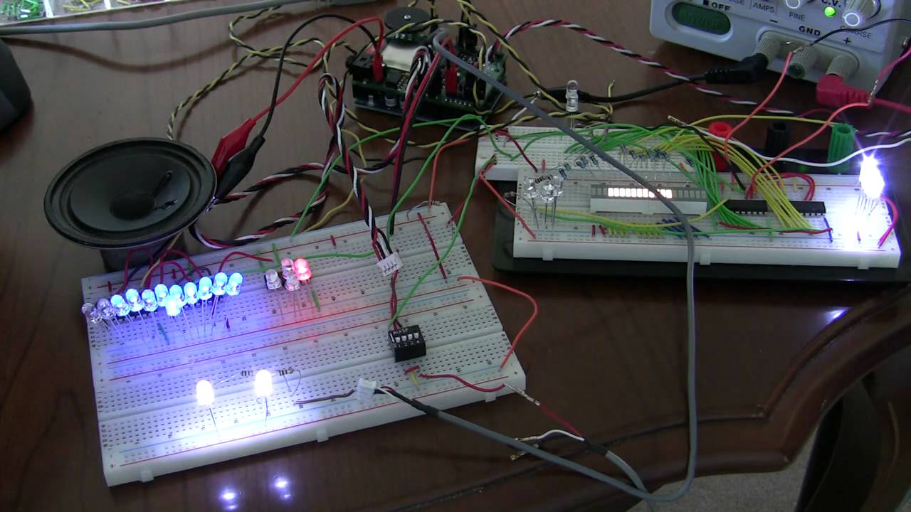

 (I much prefer perf-board)