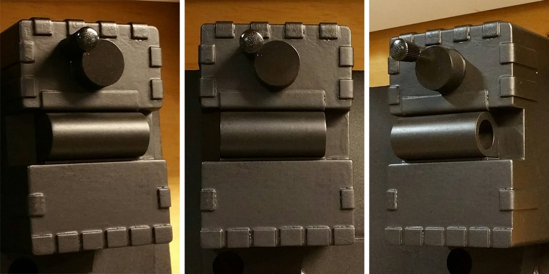
Astyanax's Low-Budget mostly-Gagnon (Paranorman) Scratch Build (pic heavy)

10. CRANK KNOB

Although the crank knob is technically part of the crank generator, I wanted to give it its own build section. There were a lot of steps involved, and it was worth giving it its own attention.

NOTE: It was about this time that I realized that many of the choices I was beginning to make have been leading to a some kind of hybrid GB1/GB2 style pack. But I don’t mind; I’ve got things I like about each, so I’ll be picking and choosing whichever aspects I like best from each. But this is probably more of a GB2 pack than anything else now. I will try to point out the obvious differences as I go, but I really think the two packs are very, very close.

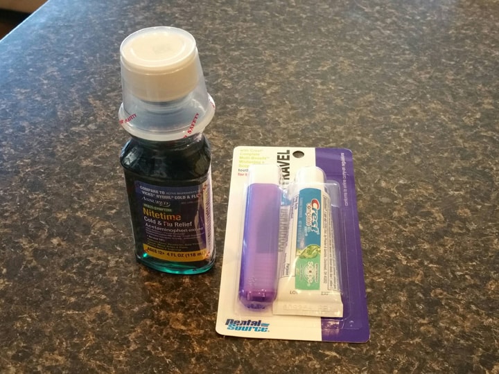
First, I made a trip to the dollar store to see what I could find. I ended up bringing home some knockoff NyQuil (I was looking for a cap that was 1-1/4" or so in diameter), and a travel toothbrushing kit:

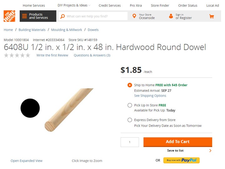
I also picked up a half-inch wood dowel from Home Depot:

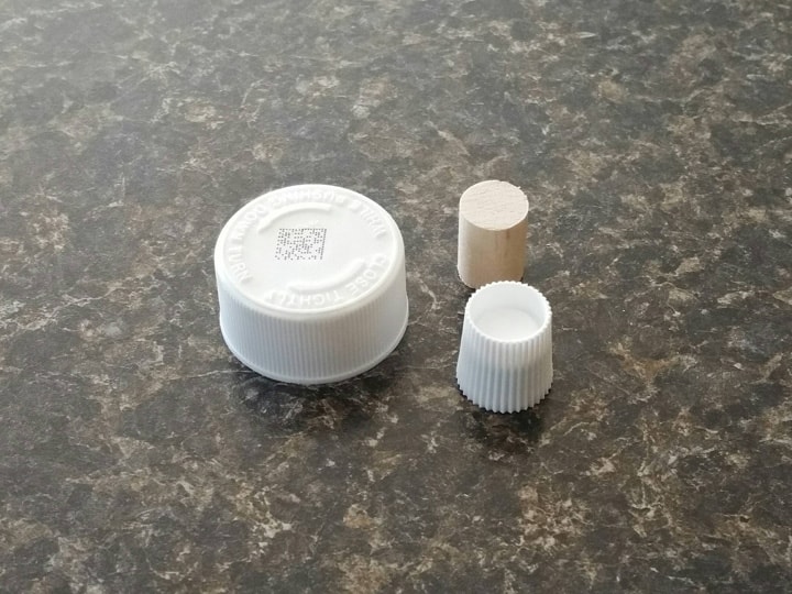
After tossing out the parts I didn’t need and cutting a 3/4" piece of the dowel, these are my working parts:

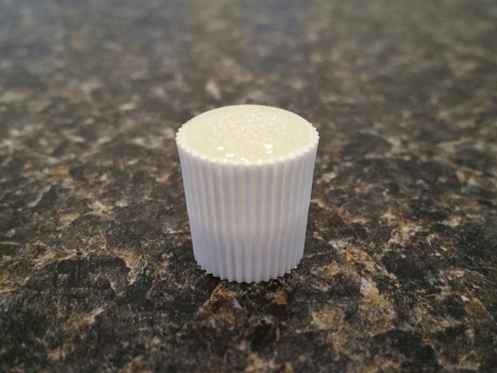
First off, I wanted to fill the toothpaste cap, as it will be the crank handle. I used Loctite 2-part 5-minute epoxy, and filled the cap with the mixture. The surface tension of the epoxy is such that I was able to get a little bit of a “dome” of the material without spilling it. I’m not sure I was going for that effect, but I like it. :slight_smile:

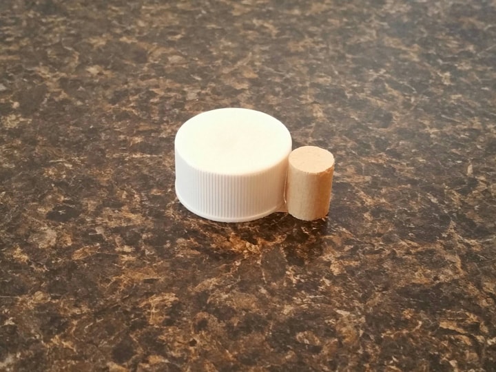
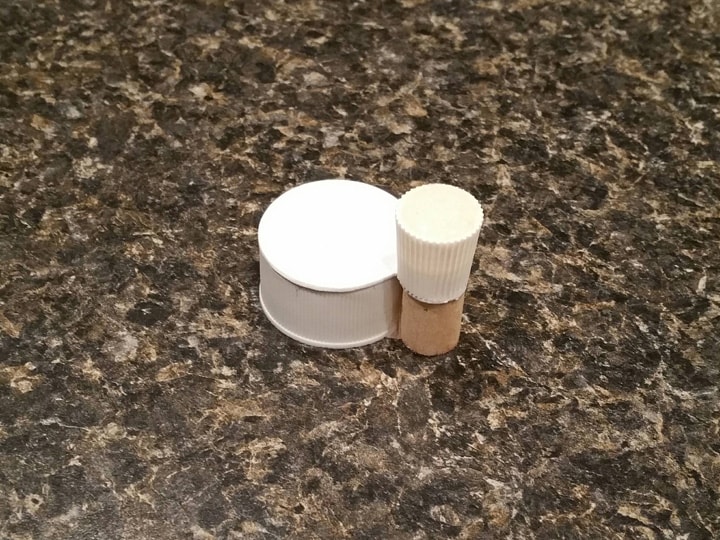
After sanding the top of the cough syrup cap so that it was smooth, I used epoxy to glue the dowel piece to the side of the cap.

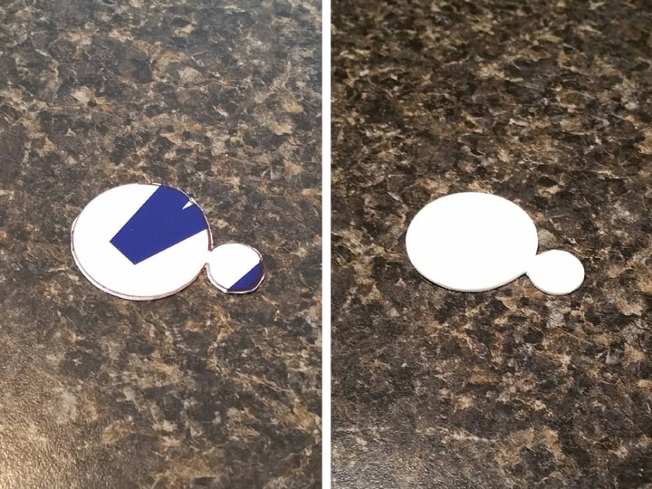
Once cured, I traced the top of this part onto some leftover no-parking sign plastic and cut it out slightly oversized with lexan scissors. I then sanded it smooth with an emory board and 400-grit sandpaper, until it fit the top of the part nearly perfectly.

Next, I superglued the plastic sheet to the top of the part, and then superglued the toothpaste cap to this:

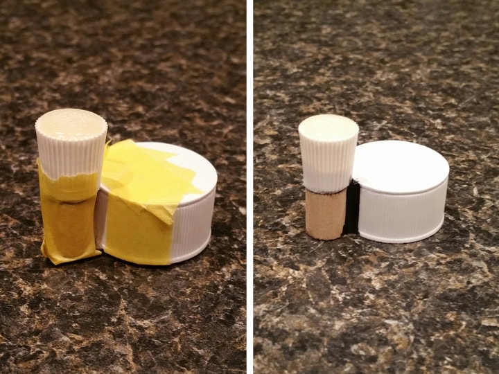
I wanted to see if I could smooth the transition from dowel to large cap, so I carefully taped off the corner on both sides, and used the black Dynaflex 230 as a filler. Using the black (instead of white) caulk made it easier to see its coverage.

I removed the tape almost immediately. Ready for paint!

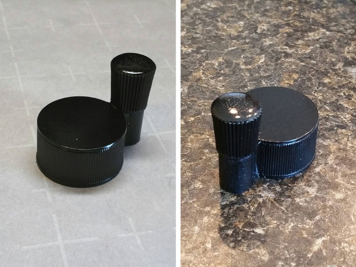
Painting was simple: two coats of flat black spray, followed by two coats of satin black (I wanted it pretty glossy). The GB1 version of this part is gray; GB2 is shiny black.

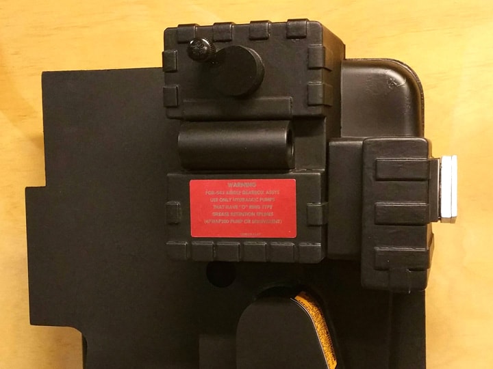
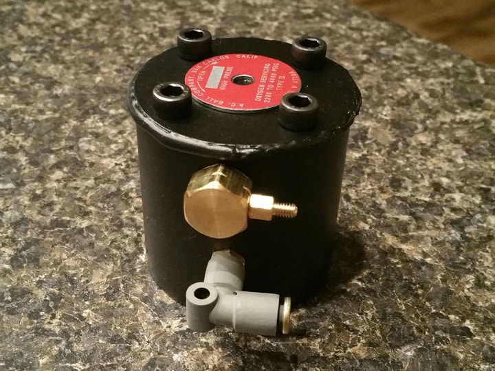
All done! Here it is glued (with epoxy) onto the crank generator:

Yeah, it’s a little large, but looks good in the grand scheme as far as I’m concerned. :slight_smile:

Next post, I’m going to take a step back from the components of this build, and (mostly) scratch build all the fittings: Legris, Clippard, banjo, boots, etc. I need them for the next several components!

Thanks for reading!

Bill

RUNNING PARTS COST:

$1.00 - Cough syrup bottle (dollar store)

$1.00 - Travel toothbrush kit (dollar store)

$1.85 - 1/2" x 48" wood dowel (Home Depot)

$136.09 - previous total

$3.85 - this stuff

TOTAL: $139.94

Loving the craftsmanship! It’s taking me back to my early build days. I love the crank knob idea!

Great scratch building lad, nice how your doing the costs too , keep it lit! :wink:

Thank you guys so much for the kind words. Lots more coming, I’m making great (but slow) progress!

11. FITTINGS

In this section I will be going over my lower-cost emulation of the various fittings that appear on the pack. Some are close, and some are close enough. I managed to average less than $3 each for every type of major fitting this build needs. (If you think that’s a lot per fitting, understand that the fully-authentic versions of some of these fittings can go as high as $20-$30 each!) Hope you enjoy!

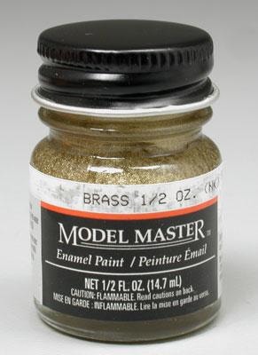
NOTE: As will be pointed out below, some of these parts have been painted or touched up with brass-colored model paint. I highly recommend Testors Model Master brass enamel, as it is bright, shiny, oil-based for longevity, and works well with just one coat. If you have a hobby shop nearby, I recommend trying to get some. It’s not worth buying online.

A. “Legris” Elbow (x3, $3.17 each)

The Legris elbow appears:

GBfans reference page with more details

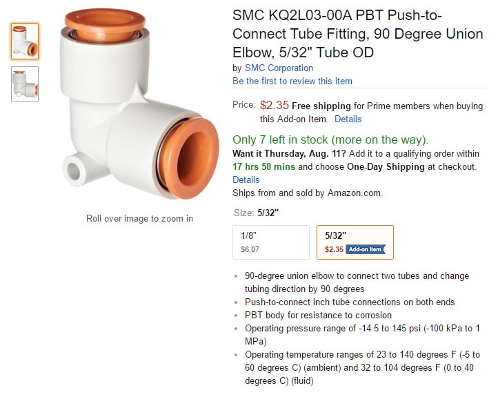
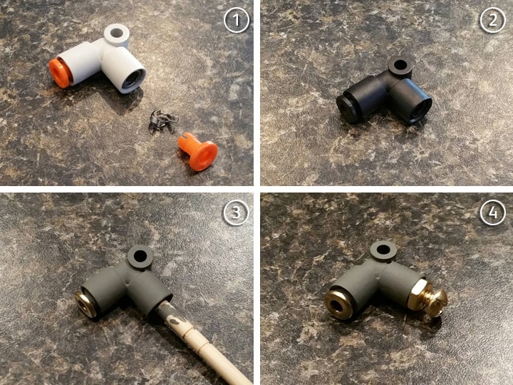
For my Legris elbows, I found these 5/32" tubing elbows on Amazon:

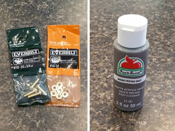
From Home Depot, I picked up brass #10-24 x 3/4" screws and brass #10-24 nuts, for less than a dollar per pack. I also bought pewter grey paint from Michaels for fifty cents.

To convert this fitting, I did the following:

Step 1: I removed the orange plug from the shorter side with pliers, and then removed the metal “basket” deep inside the fitting with a combination of slotted screwdriver and needlenose pliers. It was a bit difficult; the trick is to keep prying back and forth until it begins to surface, and then grab it with the pliers. The metal ring I left intact. I saved the orange plug for the banjo elbow later!!!

Step 2: I sprayed the fitting with flat black.

Step 3: I hand-painted the whole fitting with two coats of the pewter grey, holding it with a chopstick while painting. I then painted the remaining tubing plug with brass model paint.

Step 4: The screw will now screw in quite tightly with a little elbow grease.

For installation, the idea here is to drill a hole in the wall of whatever component of the pack, put the screw through from the inside facing outward, and tighten the nut from the other side. Holding the screw in place, I can then twist the fitting onto the screw until it meets up with the nut. No glue of any kind should be necessary!

(Okay, so I guess I didn’t have to go with brass screws. But they were the same price!)

$2.35 - 5/32" push-to-connect tubing elbow (Amazon)

$2.35 - 5/32" push-to-connect tubing elbow (Amazon)

$2.35 - 5/32" push-to-connect tubing elbow (Amazon)

$0.98 - #10-24 x 3/4" brass screws (Home Depot)

$0.98 - #10-24 brass nuts (Home Depot)

$0.50 - pewter grey acrylic paint (Michaels)

Total: $9.51

Total cost per fitting: $3.17

B. “Legris” Straight Connector (x2, $2.11 each)

Two Legris straight connectors appear, side by side, on the side of the attenuator. If you’re building a ghost trap pedal, you’ll need a third.

GBfans reference page with more details

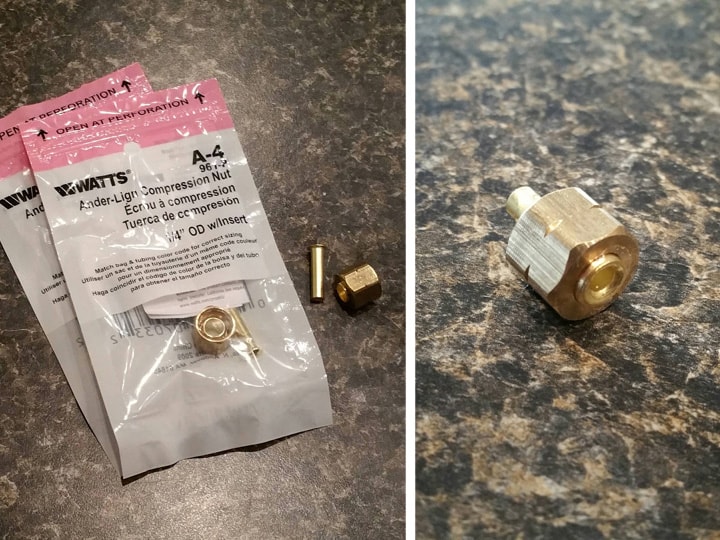
All I needed for this part were two 1/4" compression nuts:

These nuts come with an insert, which I glued permanently into the nut with epoxy. The 5/32" red tubing can be jammed into the insert, IF the end of tubing is clipped to a sharp point prior to inserting. More tubing details in a later post.

The entire nut will then be glued to the attenuator with E6000.

$2.11 - 1/4" brass compression nut (Home Depot)

$2.11 - 1/4" brass compression nut (Home Depot)

Total: $4.22

Total cost per fitting: $2.11

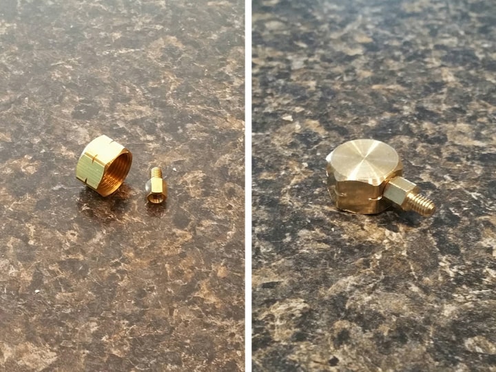
C. “Clippard” Elbows (x3, $2.75 each)

The Clippard L-fittings can be found:

  • On the HGA

  • On the Beam Line

  • On the Ion Arm (for GB2 packs–GB1 uses a slightly different part here)

GBfans reference page with more details

These fittings have a hose barb as well, but I don’t care about that, since I’ll be covering it up with the hose anyway.

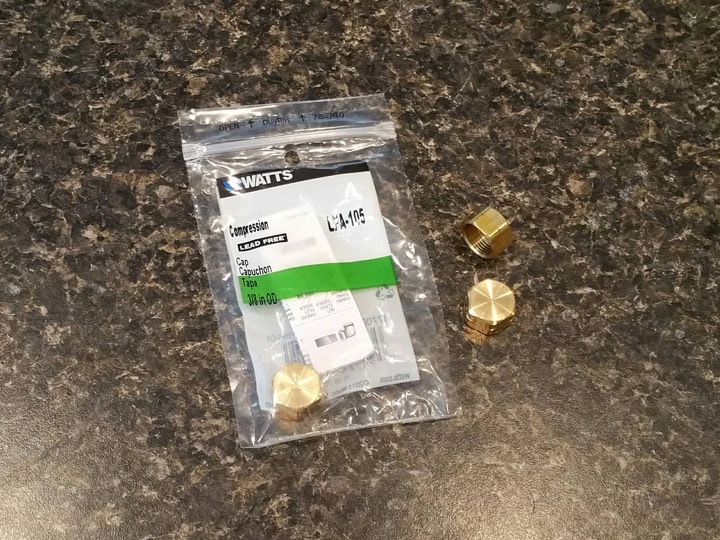
To simulate them, I picked up three 3/8" brass compression caps from Home Depot for the main body:

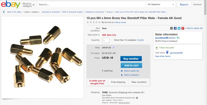
For the elbow part, I ordered these brass hex M4x6mm standoffs from eBay, ten for just over a buck:

I epoxied a standoff to the side of the compression cap, and that’s it!

Yes, they are a little stubby, but still shiny and metal and inexpensive. :slight_smile:

These will be attached to their respective components with E6000. The tubing will have to be glued over the threaded end of the standoff. I’ll probably use quick-set epoxy.

$2.36 - 3/8" brass compression cap (Home Depot)

$2.36 - 3/8" brass compression cap (Home Depot)

$2.36 - 3/8" brass compression cap (Home Depot)

$1.16 - M4x6mm brass hex standoffs, 10-pack (eBay)

Total: $8.24

Total cost per fitting: $2.75

D. “Banjo” Elbows (x2, $0.74 each)

The “Nycoil” banjo elbows are attached to the end of the particle thrower. You need a third for the pedal if you’re building a trap.

GBfans reference page with more details

These discontinued parts can be very expensive to track down. My idea was to use a piece of square dowel. I had leftover dowels from the gearbox/crank generator, so there was no cost for that part. I also picked up a pack of half-inch #8-32 screws and nuts from Home Depot

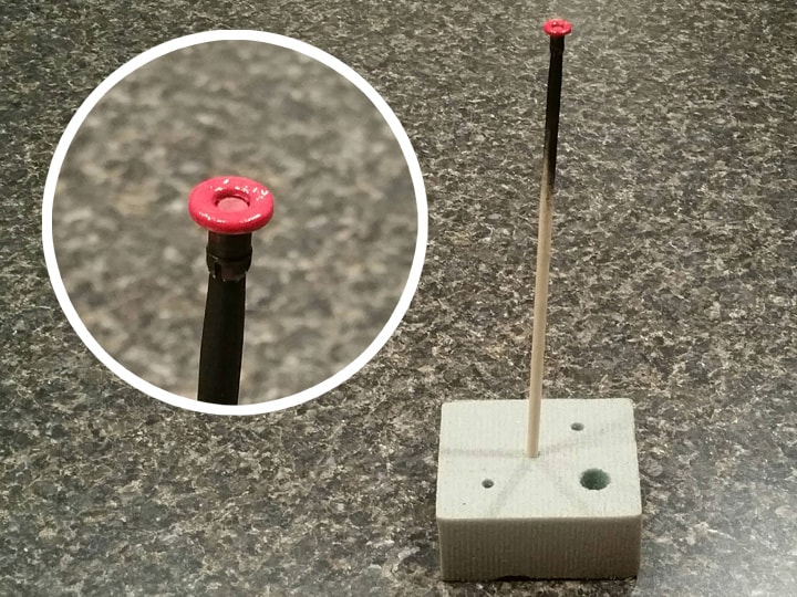
Remember those orange tips from the Legris elbows? I sprayed them flat black and hand-painted the tips with a couple coats of glossy red acrylic paint. Model paint would work well here also. I used a chopstick anchored in a piece of floral foam to hold it up for painting.

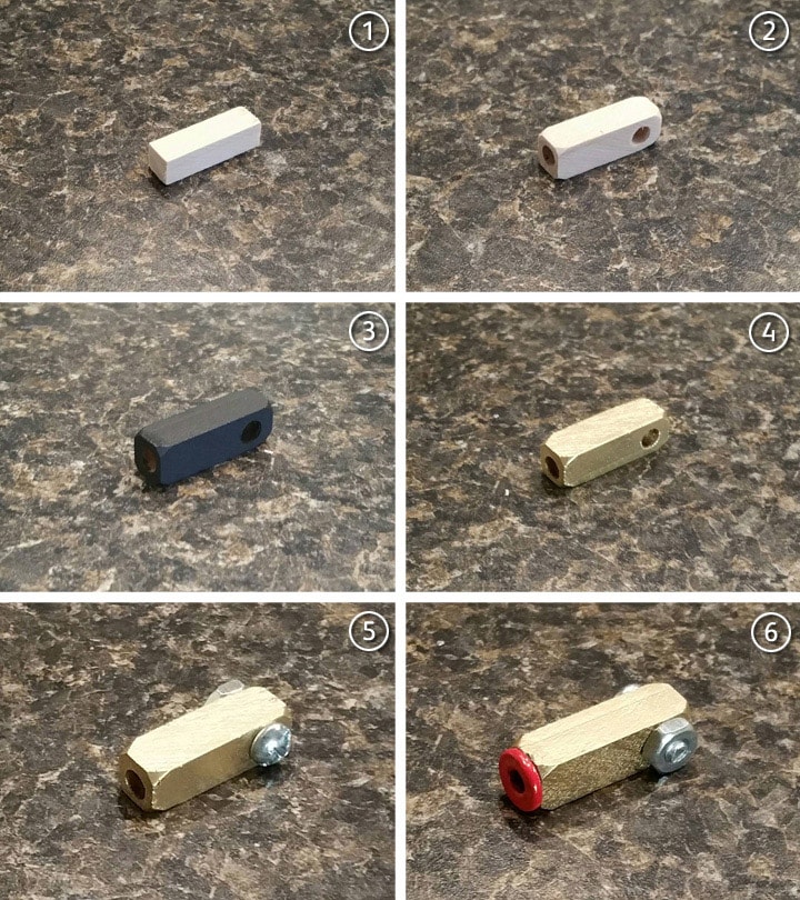
Then, to build the actual fitting, I went through the following steps:

Step 1: I cut a 1-1/8" piece of 8mm square dowel (the pack from Wal-Mart was metric).

Step 2: I drilled a 3/16" hole in one end, about a half-inch deep. I also drilled a 3/16" hole all the way through the side, near the back. Note: These pieces want to split. To avoid splitting, drilling the hole through the side BEFORE cutting the dowel to length can help. So can using brad point drill bits, which cut more precision holes. Splitting or chipping can also be repaired with glue or Bondo spot putty.

I also gently sanded off the corners with 400-grit sandpaper.

Step 3: I primered the piece with flat black spray, held up on a chopstick.

Step 4: I hand-painted 2 coats of brass model paint, again holding up the piece on its chopstick.

Step 5: I insterted the #8-32 screw through one side, and fixed it on the other side with one of the nuts.

Step 6: I inserted the red Legris tip into the end. It was necessary to widen this hole just a little. :slight_smile: Glue was not necessary.

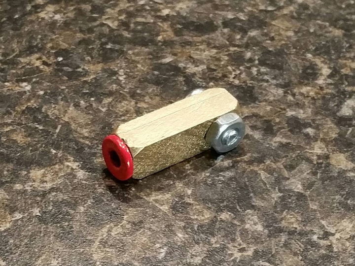
All done! The only thing that would have made this better would have been to find cheap hex-head screws. But no big deal.

I will probably attach these to the wand with epoxy or E6000.

$0.98 - 1/2" #8-32 round head combo machine screws & nuts (Home Depot)

$0.50 - Gloss red acrylic paint (Michaels)

Total: $1.48

Total cost per fitting: $0.74

E. Cable boots (x6, $0.99 each)

As near as I can tell, there are a total of six cable boots at the ends of the following tubing lengths:

  • blue tubing attached to injector and cyclotron, both ends (2)

  • red tubing attached to injector and cyclotron , both ends (2)

  • blue tubing attached to ion arm and PPD, both ends (2)

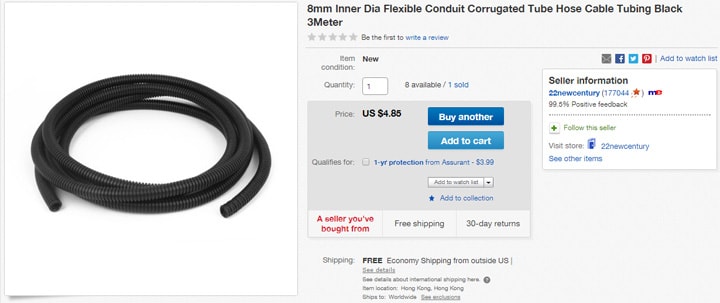
A lot of people use oversized flexible straws, or even small split loom wire covering, so I went with this NON-SPLIT loom (a.k.a. “corrugated tubing”) I found on eBay:

This tubing will come in handy elsewhere on the pack, so it’s not as expensive as it seems.

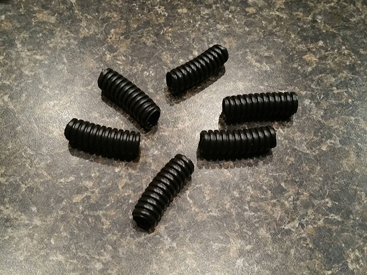
They’re not a perfect match, but they still look pretty good. I cut them to about 1-1/4" in length:

The corrugated tubing is not a tight fit over anything, so I will probably secure these boots with E6000 or epoxy.

Total: $5.95

Total cost per fitting: $0.99 (only using six)

So that’s it! Lots of fittings ready to go, lots of money saved! Here’s the whole collection:

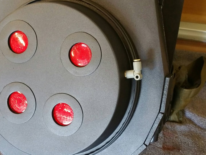
Before I close out this post: I went back to my cyclotron and installed one of the new Legris elbows. I simply drilled a hole in the right spot, ran the screw from the inside, tightened the nut on the outside, and screwed the elbow right on. No glue, as predicted!

Next post, I’m making the N-filter.

Thanks for reading!

Bill

RUNNING PARTS COST:

$3.69 - Brass model paint (local hobby shop)

$9.51 - Legris elbows (3)

$4.22 - Legris straight connectors (2)

$8.24 - Clippard elbows (3)

$1.48 - Banjo elbows (2)

$4.85 - Cable boots (10)

$139.94 - previous total

$31.99 - this stuff

TOTAL: $171.93
The stuff you are doing in here is incredible. Bravo dude!!

12. N-FILTER

Okay, time for my three dollar N-filter. :slight_smile:

This part is mounted at the bottom of the cyclotron. My version is kind of a GB1/GB2 hybrid, as I liked colors and textures from both. Beause my cyclotron is removable, I had to make sure not to also attach the N-filter to the main body.

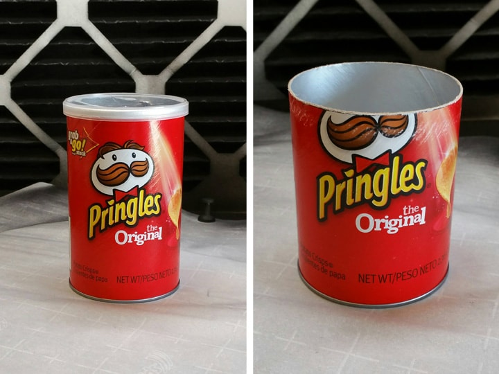
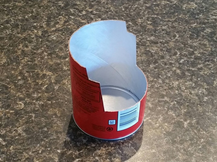
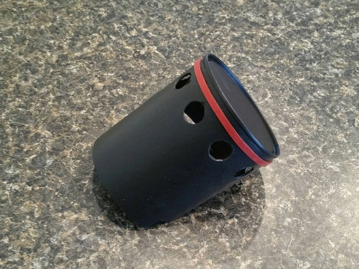
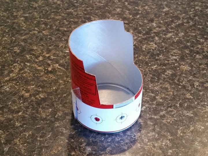
Per Paranorman, I started off with a mini can of Pringles from the dollar store. After eating the chips and lightly washing the inside, I drew a line about 3-1/4" up from the base all the way around it. I did this by holding my hand steady on a support with a fine-tipped Sharpie in-hand and rotating the can around with the tip of the pen stationary on it. I then carefully used an x-acto knife to cut it off. A light sanding smoothed it just right.

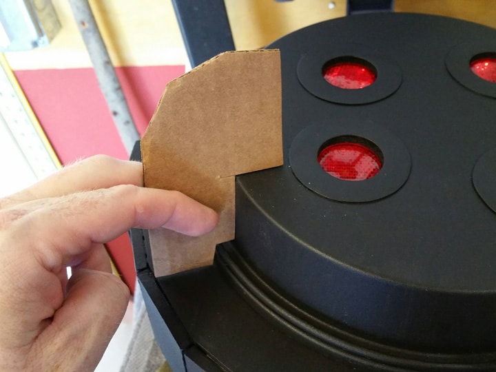
Next, after much trial and error with pieces of paper, I cut a cross-section template out of cardboard, laying out just how the N-filter can is going to sit on the cyclotron and main body.

Once I was happy with my template, I used it on the can, cutting the step shape, drawing a line around the can where it ends at the top, and then tracing it out in reverse on the other side. It was necessary to hold the can up to the cyclotron a few times to figure out how far around to cut.

I recommend picking up a couple extra Pringles cans just in case. They’re cheap, and you can snack on them. :wink:

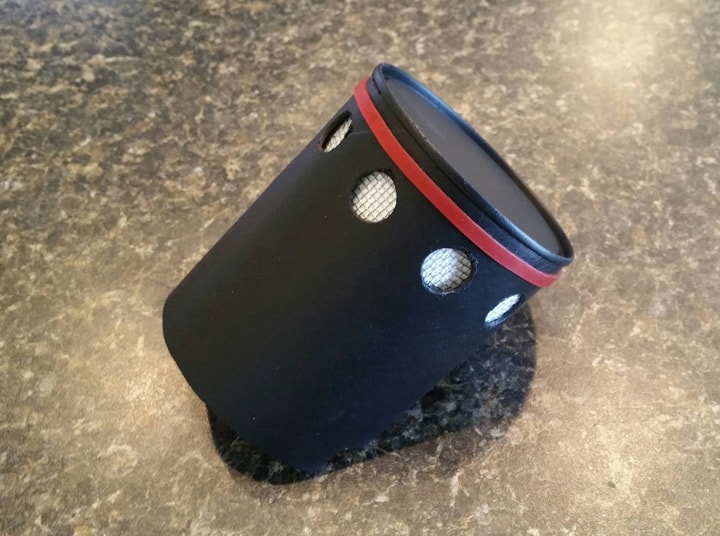
To position the holes, I used Namssorg’s excellent hole template. I decided to go with the evenly-spaced holes of the GB2 pack instead of the GB1 spacing. I printed the 3" diameter template, scaled up to 101%. This fit the Pringles can perfectly.

I taped the template on the can and poked holes with a pen where the centers of the holes would be.

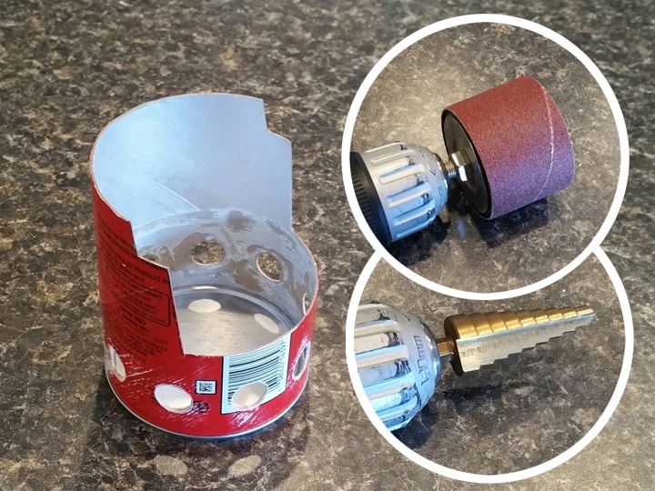
Drilling the holes was exceptionally difficult. The problem is that the inner layer of foil wants to tear, causing ugly, torn holes. After much testing on spare pieces of Pringles cans, I came to the conclusion that the best drill bit to use was a step bit. Using this bit and almost no pressure, I cut 1/2" holes all the way around. The foil still tore badly, but at least the holes were pretty clean on the outside.

To clean them up, I lightly sanded the outside with 400-grit sandpaper. For the inside, I really aggressively sanded them using a sanding drum on my drill (dirt cheap at Harbor Freight). The process was repeated a few times until the holes were pretty clean inside and out.

I also used a 1/2" dowel to help with the smoothing and sanding. Holding the dowel where its tip is just beginning to come inside gave the sanding drum something to cut against as it took off the inside foil pieces.

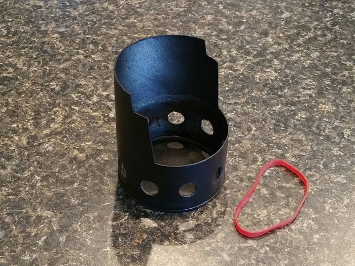
Next, I painted the whole thing with my usual formula of two coats flat black and a very light coat of satin.

Later on I decided I wanted to recreate the “weld” effect on the N-filter. Although I did it later, masking things off, it would have made more sense to do it now, prior to painting.

Time for the red line around the base. After much thought, I decided that masking and painting was going to be too difficult and imprecise, so I picked up a bag of rubber bands from the dollar store. Inside the bag I found a dull red rubber band of just the right thickness and diameter. I slipped it on and called it good!

There’s no gluing for now, as I didn’t want to risk leaving residue. We’ll see how long it lasts; it’ll probably need the occasional adjustment. Maybe the tiniest drips of superglue would help, but I don’t want to if I don’t have to. The rubber band is going to deteriorate over time, so I need to be able to replace it easily every couple years.

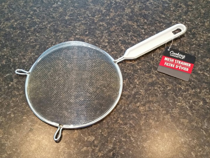
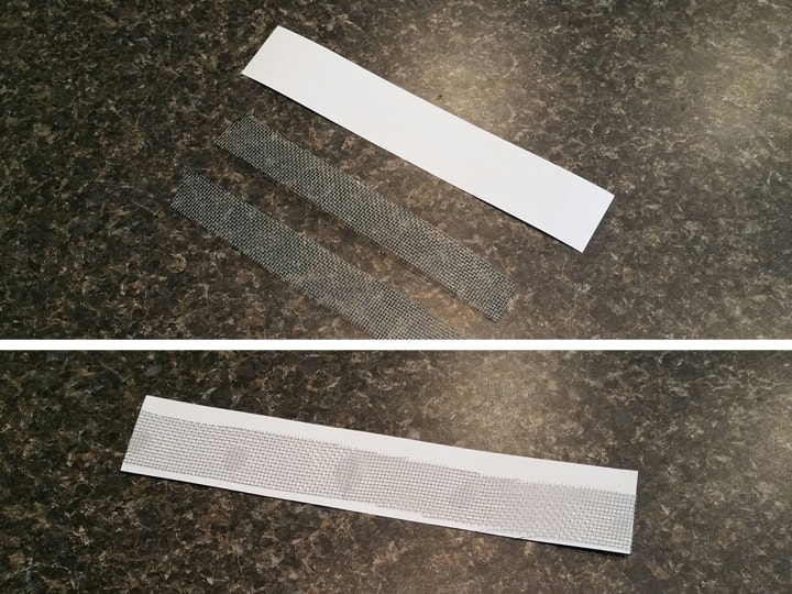
For the details inside the holes, I picked up this stainless steel strainer from the dollar store:

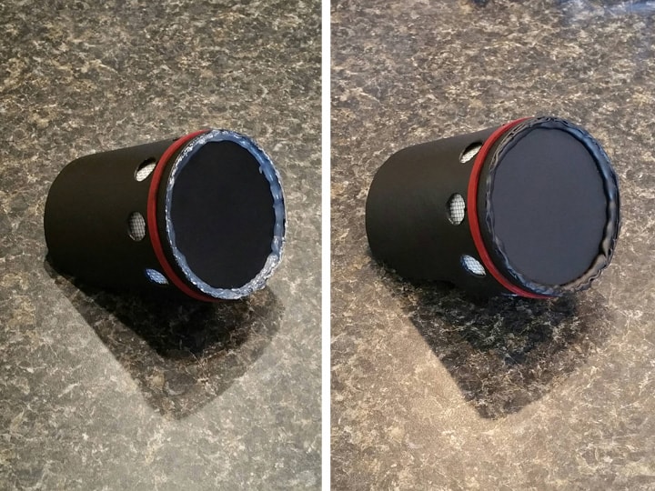
After cutting the mesh out of the frame, I cut some strips, as well as a longer strip of white card stock paper to about 8-3/4". I test fitted inside the N-filter, and then used hot glue to secure the mesh strip to the paper. Low-temp hot glue did the trick, and I smashed it flat right before cooling.

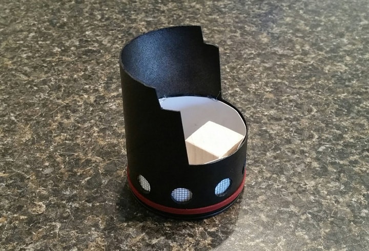
I then rolled it and insterted the strip into the N-filter, using a couple strategically located dabs of hot glue to hold it in place. The “unwinding” tension of the strip also helps it hold its place, so I feel it’s pretty secure.

To secure the N-filter to the cyclotron, I took advice from Paranorman’s instructions, and cut a piece of a 1" square dowel (left over from the Alice frame spacers) and used E6000 to glue it to the bottom of the can.

It was at this time that I made the last-minute decision to recreate the “weld” effect. I wasn’t going to do this (I like a “cleaner” look), but I kind of felt the pack was beginning to look too clean. So I applied a bead of hot glue around the rim of the base of the can, doing my best to fill the little groove.

I should have done this step before painting, so it was necessary to mask off the other surfaces before hitting it with a light coat of flat black.

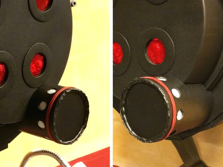
I’m pretty happy with the result:

Finally, I glued the N-filter onto the cyclotron ONLY using E6000 on the end of the wood dowel. It feels mostly secure; I’ll keep an eye on it to see if I need to do anything more.

Next post, it’s time to make some nice labels!

Thanks for reading,

Bill

RUNNING PARTS COST:

$1.00 - Mini Pringles can (dollar store)

$1.00 - Strainer (dollar store)

$1.00 - Bag of rubber bands (dollar store)

$171.93 - previous total
$3.00 - this stuff

TOTAL: $174.93
OLD SCHOOL!

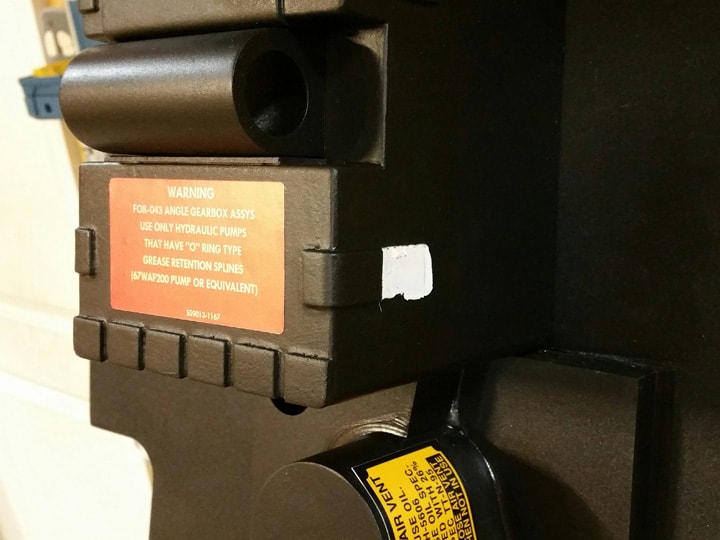
13. LABELS

I’m far enough along now that I need to start putting labels/decals on the pack; if I wait too much longer, It’ll become more difficult as components get in the way.

I know that sixteen bucks seems pretty expensive just for labels, but considering that I managed to produce high quality labels (including the metallic ones), and considering that labels that are sold elsewhere (when available) can be 3x-4x this cost, I feel it was worth it.

First off, I used valentino42’s amazing printable labels as my foundation, with my inkjet printer.

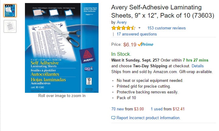
For the “vinyl” style labels, I elected to print onto card stock, and to MANUALLY laminate them. A traditional laminator machine is not acceptable, because the laminated plastic does not actually stick to the printed material. So instead, I decided to laminate the first page of valentino42’s PDF using these self-adhesive laminating sheets from Avery. I found a 10-pack on Amazon for six bucks.

Using the sheets was very straightforward. Print the page, stick one side onto a sheet, and then cover it with another.

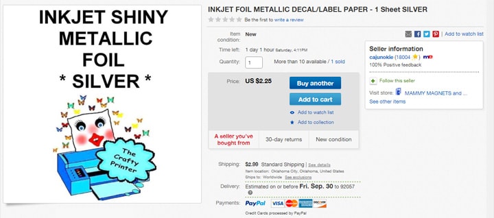
For the metallic sheets, I tried a few different homemade techniques, none of which I was very impressed with, until I encountered this inkjet printable metallic foil on eBay:

It’s sold by the sheet, and I was able to print valentino42’s second page onto the one sheet successfully in the first attempt, but if you try this, you might want to purchase more than one to save on shipping, just in case. The instructions say don’t print at high resolution, but I had great success doing just that.

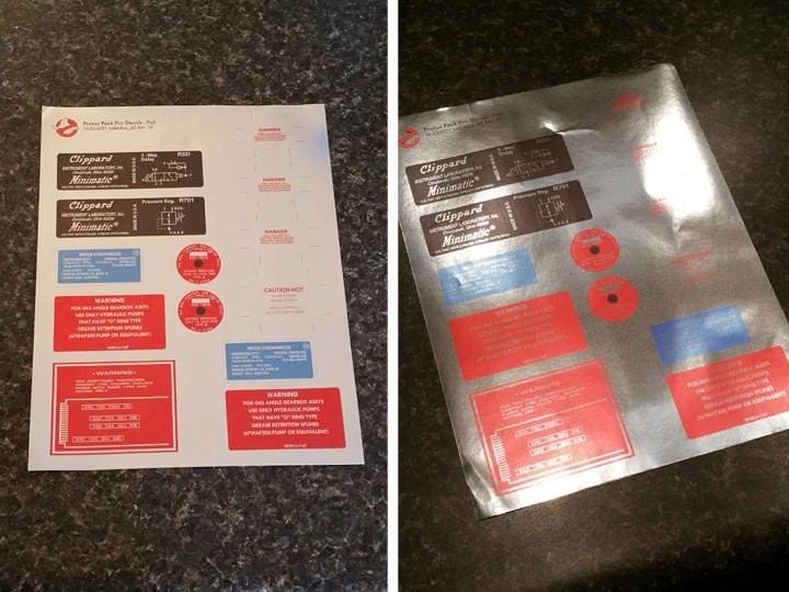
The metallic paper is very shiny, and looks different under different lights. Here’s an example. Same sheet, different lighting:

Anyway, I had my printouts done and my labels were ready to go:

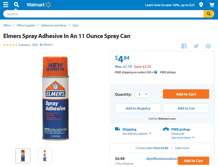
For sticking them onto the pack, I opted to use Elmer’s Spray Adhesive, on sale at Wal-Mart:

For my first attempt at sticking a label, I went with the largest: the big red “Danger” notice on the back of the pack. I cut it out with an x-acto knife, and positioned it by hand until I was happy with it. I then used masking tape to mark the edges. After that, I sprayed the back of the label with the spray adhesive, and used the masking tape as a guide to lay down the label.

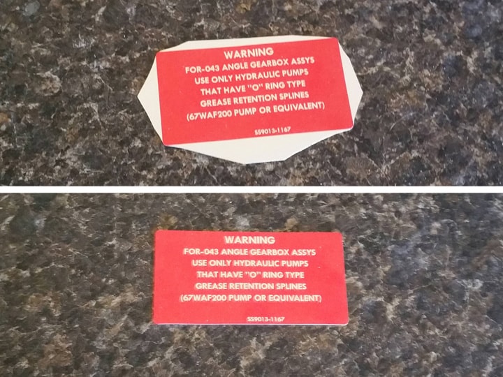
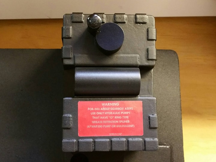
Next, I cut out the gearbox label; this one’s metallic and has rounded corners, so my technique was to first cut the corners carefully with scissors, and then cut the straight edges with the x-acto knife.

It was necessary to trim the corners just a tiny bit after this, but it came out quite nice. The metallic sheet is peel-and-stick, so I didn’t need to use the spray adhesive with that one.

After this, I cut the two labels for the N-filter (non-metallic) and stuck them on with the spray adhesive:

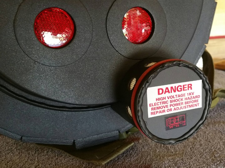
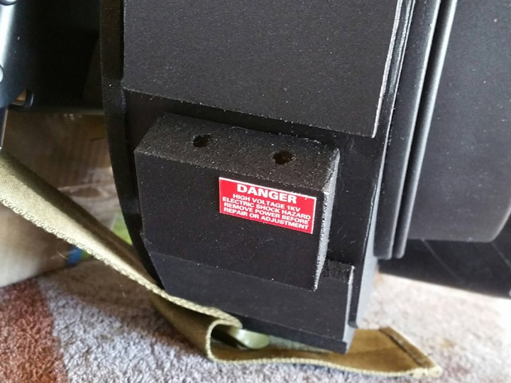
Gaining some confidence, I moved on to the small red “Danger” notices on the cyclotron

…and the left block on the synchronous generator.

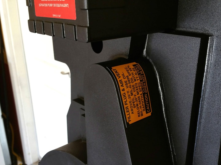
Finally, I applied the yellow filler plug label on the synchronous generator.

That’s it for all the parts I’ve built so far. Going forward, I will apply labels as I make components.

Next post, I will add the neck padding on the Alice frame and the head padding on the motherboard. Yep, these are a couple easier steps prior to tackling that gun mount. It’s important to mix it up to keep things interesting! :slight_smile:

Thanks for reading,

Bill

RUNNING PARTS COST:

$6.19 - Self-adhesive laminating sheets (Amazon)

$5.24 - Metallic label paper (ink-jet, 1 sheet) (eBay)

$4.84 - Elmer’s spray adhesive (Wal-Mart)

$174.93 - previous total
$16.27 - this stuff

TOTAL: $191.20

This is seriously the nicest Paranorman build I’ve seen in a long time.

Thanks so much guys for the compliments! I can’t tell you how much fun this has been. By breaking up each component into a separate project, it’s really kept the the build fresh and fun. Every day I’m doing something different. :slight_smile:

Lots more coming over the next few days.

Bill

That’s how I feel about my foam builds. Especially when I work on a new style or scale. Keep up the good work! Can’t wait to see the end result!

I am stealing some of these ideas. The chip can looks great. I am going to try that.

14. NECK & HEAD PADDING

Keeping things interesting, I wanted to finish the back side, get it out of the way, try the pack on, etc. :slight_smile:

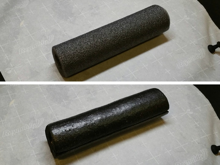
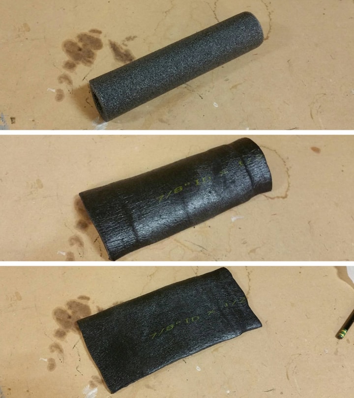
As many have done before me, I picked up a six-foot piece of pipe insulation from Home Depot (the kind split down one side). After cutting an 8-1/2" length, I zapped it with my heat gun to close up the outer layer of cells just a bit. A hair dryer would work just as well. This had the effect of giving the piece a sheen, and it darkened its color just a bit.

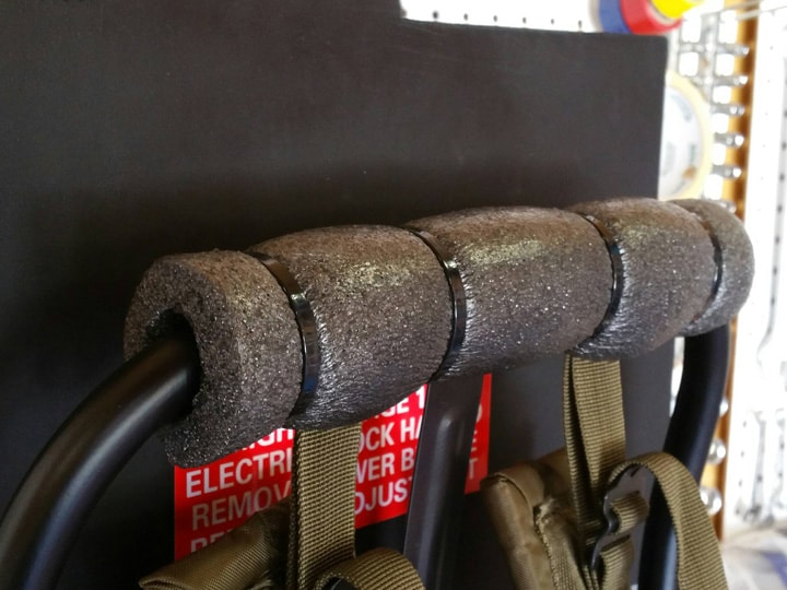
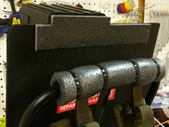
To secure the insulation on the Alice frame, I simply placed the piece on the top of the Alice frame, open seam downward, and secured it with four 11" cable ties from Home Depot. I don’t believe any glue or other securing mechanism is necessary.

There is also a piece of foam at the top of the motherboard, to protect the board (or my head) from bumps. But rather than try to hunt down a piece of foam and worry about color or material, I decided to use another piece of the pipe insulation.

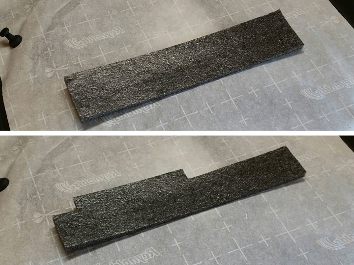
After cutting a 12" or so length of the insulation, I proceeded to heat it evenly with my heat gun (again, a hair dryer will work), pressed it flat with a board, flipped it over, heated it again, pressed it flat, and so on, for several minutes. Eventually the piece started to flatten out, and I had a workable piece of foam.

I then cut an usable 2" strip, about 10" long. I fitted it to my motherboard and cut around the “tab” at the top, using my x-acto knife (which slices through this stuff quite easily).

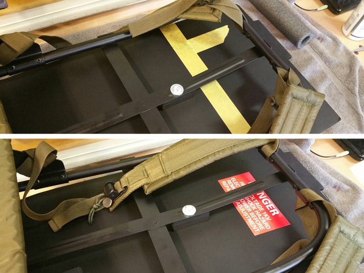
After that, I stuck it to the motherboard, using the spray adhesive I had purchased for applying labels.

All done! Super easy!

Next post, it is time to move on to the gun mount box. Massive build coming!

Thanks for reading,

Bill

RUNNING PARTS COST:

$1.24 - Polyethylene pipe insulation (6’ length) (Home Depot)

$2.44 - 11" cable ties (10-pack) (Home Depot)

$191.20 - previous total

$3.68 - this stuff

TOTAL: $194.88

15. GUN MOUNT

The gun mount box is particularly difficult, even though it is simpler in design than the gearbox/crank generator. The challenge here is that since the proton gun is going to be hanging from this box, it needs to be mounted exceptionally SECURELY, because it alone will be supporting the weight of the proton gun. We don’t want components falling off every time there’s a little tug on the wand!

So, to make this more stable, I opted to bolt a piece of MDF to the motherboard, in order to serve as an extra wall for the gun box. That way, the V-hook could be mounted to this piece of MDF. More on that later.

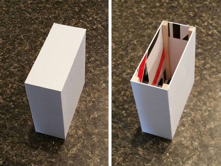
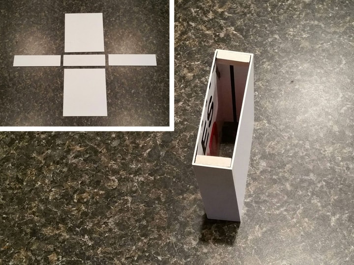
First off, I had to build my box. This went very similarly to the gearbox assembly in a previous post, so I won’t go into fine details here. But I took lots of measurements of my available space as I went along, and tweaked the measurements of the box(es) just a tiny bit to allow it to all fit just right.

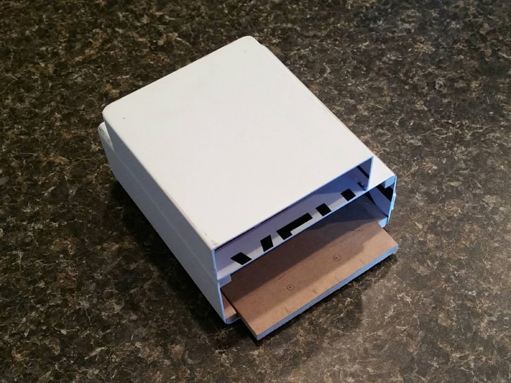
I made the box out of no-parking sign plastic (bought a new one):

I used leftover square dowels to give me those interior corners, so that they could be rounded.

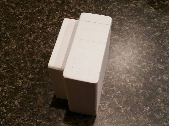
I then built the smaller box that serves as the “spacer” or “bridge” between the gun mount and gearbox/crank generator. Since this box is sandwiched between two larger boxes, I oriented the square dowels a little differently, again to aid in rounding corners.

After this, I sanded both boxes smooth, gave them their rounded corners (same as with the gearbox/crank generator), and superglued them together.

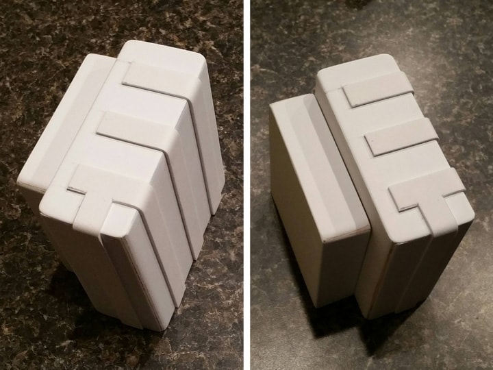
Again following a similar process as before, I applied craft foam for the details.

It was now time to prepare the pack to receive the new box. I cut a piece of the foam off the gearbox to allow for the spacer box:

As I began to realize I hadn’t built my central cosmetic plating perfectly to fit all the boxes, I realized that Paranorman had already anticipated this problem. Following the instructions in his plans, I cut a notched corner out of the rightmost plate, using x-acto knife and dremel to smooth it out.

A quick blast of black spray paint and the pack was ready to receive the new box.

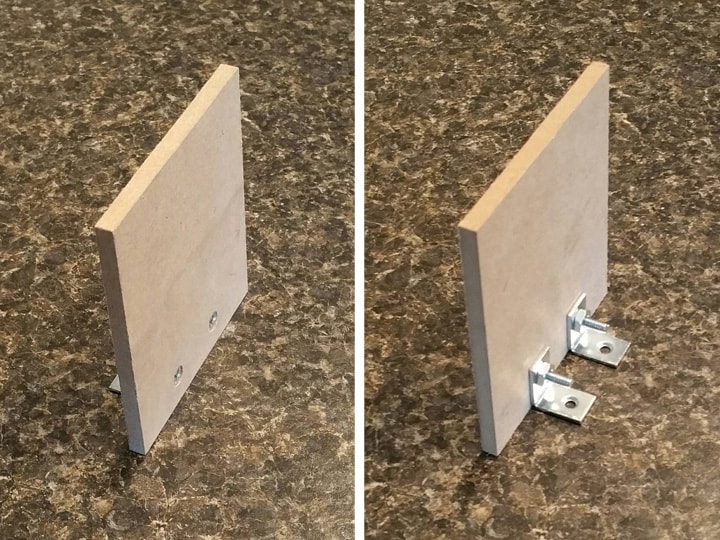
Next, I prepared my extra wall (“sidewall”) out of 1/4" MDF left over from cutting the motherboard. Notice how the idea here is that it slides between the square dowels:

I then coated the box with two coats of white glue, and then painted the box my usual flat/satin combination.

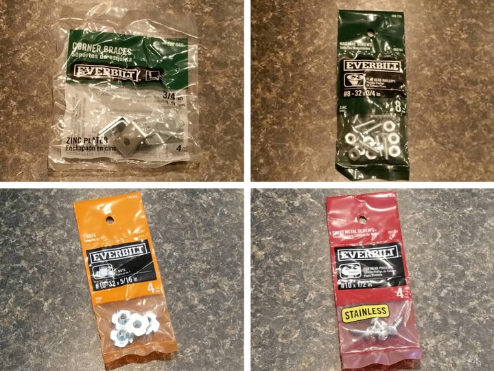
Time to pick up hardware! Below you will see that I used:

  • 3/4" corner braces

  • #8-32 x 3/4" flat head machine screws & nuts

  • #10-32 x 5/16" T-nuts

  • #10 x 1/2" round head screws

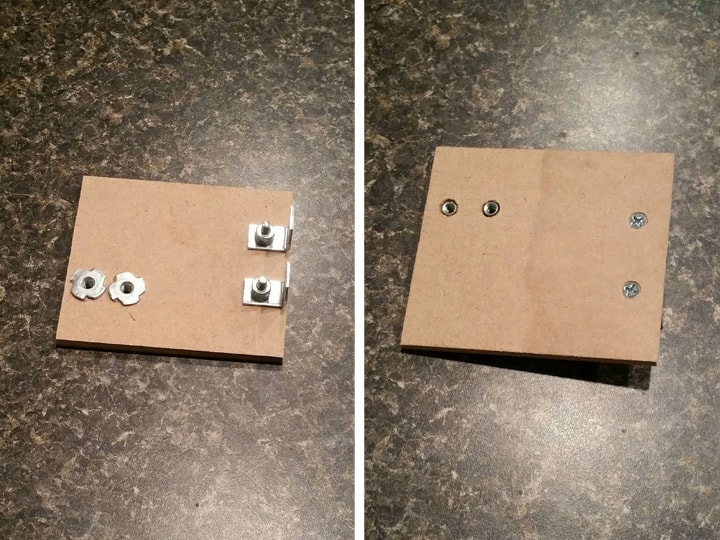
After taking careful measurements and deciding how I wanted to mount everything, I bolted two corner braces onto the sidewall using the #8-32 x 3/4" machine screws and nuts. I used an extra nut on each to lock them down.

In order to be ready to mount a V-hook, I first needed to prepare for its base plate. Knowing I wouldn’t be able to get behind the sidewall after everything else is mounted, I decided to use T-nuts to make this all happen. So, measuring carefully to allow the T-nuts to be positioned between the top two foam strips on the outside of the gun mount box, I drilled the holes and hammered in the T-nuts from the back side. This will give me something to screw into later.

To prepare the pack, I drilled two holes in the motherboard (after test-fitting everything) where the corner braces of the sidewall will go.

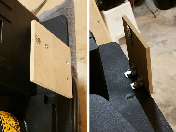
I then bolted the sidewall onto the motherboard, using more #8-32 x 3/4" screws and nuts.

I also dug out a couple small washers I had lying around to help on the outside of the motherboard. The side wall does hang over the side just a little bit, but I will paint that black later.

Next, I used epoxy on the sidewall and on the spacer box to attach the gun mount box assembly to the pack.

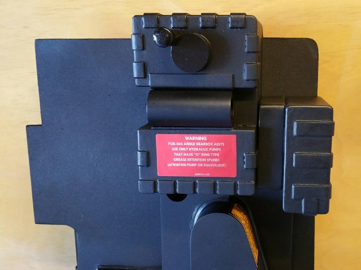
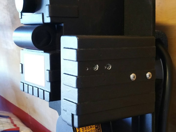
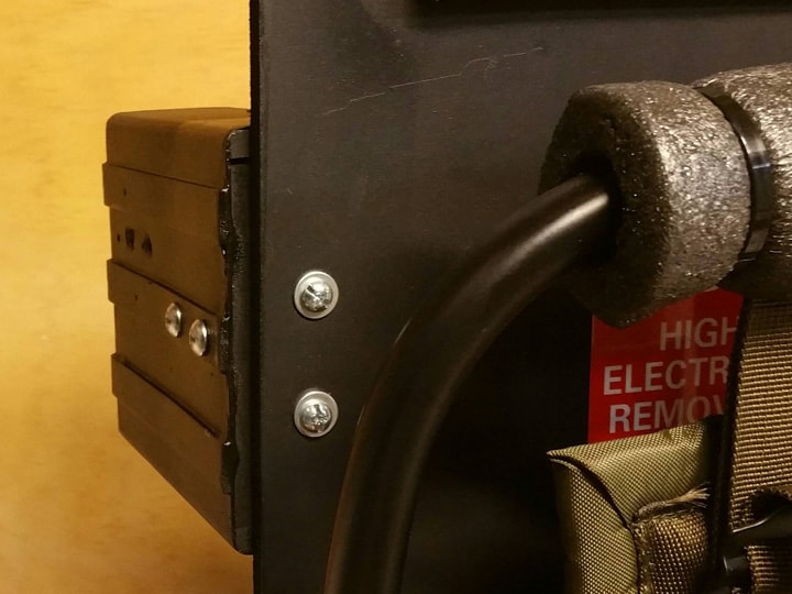
Once the epoxy cured, I screwed in two of the #10 x 1/2" round head screws (after drilling small pilot holes) through the foam strip and plastic wall into the MDF sidewall. Although these are considered “cosmetic screws”, they actually secure the entire gun box to the sidewall, which in turn is secured to the motherboard.

Later, when I attach the base plate of the V-hook, additional bolts into the T-nuts will secure the box to the sidewall even more, for even greater stability.

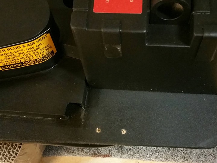
(Notice the two tiny holes in the pic above? That’s where I messed up with my first pilot holes. But they’ll be covered up in the next step.)

Finally, I masked off and blasted the back of the box with a little black paint to help it blend in with the pack better.

All done!

Next post, I will put together an actual v-hook gun mount made of wood!

Thanks for reading,

Bill

RUNNING PARTS COST:

$5.38 - 19" x 15" Handicapped Parking sign (Home Depot)

$1.97 - 3/4" corner braces (Home Depot)

$0.98 - #8-32 x 3/4" flat head machine screws & nuts (Home Depot)

$0.98 - #10-32 x 5/16" T-nuts (Home Depot)

$0.98 - #10 x 1/2" round head pointed screws (Home Depot)

$194.88 - previous total

$10.29 - this stuff

TOTAL: $205.17

16. V-HOOK

NOTE: It’s around about this time that I pretty much abandoned Norm’s plans, and started building almost exclusively off Stefan’s blueprints. Paranorman’s stuff was amazing, and really got me started, but I kinda feel I’m ready to fly now, and now that I have a lot of the techniques down, the measurements have become more important. Thanks Norm, you showed me it was possible! I’ll come back when it’s time to build a thrower! And yes, I know there are some errors in Stefan’s blueprints, but I’m learning those through research as I go.

The V-hook is the preferred method of mounting the proton gun to the pack. Its shape lends itself to more easily removing and replacing the gun. Unfortunately, it’s a custom piece and not easily sourced. At least, not for a reasonable amount of money. :slight_smile:

I researched at the alternatives: Dixie cup holders, flush mount picture hangers, sectional furniture clips, and none of them are satisfactory. It seems just too difficult to re-hook the proton gun back on the pack when you’re done using it. These other solutions also look a little weird on the pack. Nope, the only proper solution is to go with a V-hook, or at least something close. Thankfully, there is a homemade way of producing one. My favorite was pioneered by enchanted unicorn, so I will follow that layout.

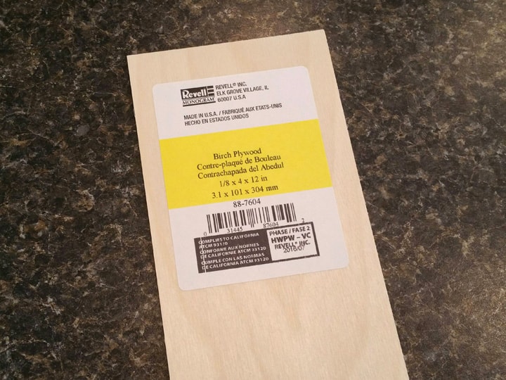
First, the wood. I was going to use 1/8" basswood, but at that thickness, it’s too flimsy. Instead I found this “Baltic birch plywood” at Michaels, $2.29 for a 4" x 12" piece that is 3mm (1/8") thick.

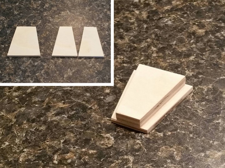
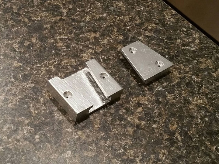
Using Stefan’s plans as a guide, I cut the male trapezoid-shaped piece, with the smaller section comprised of a double layer. I glued them together with white glue.

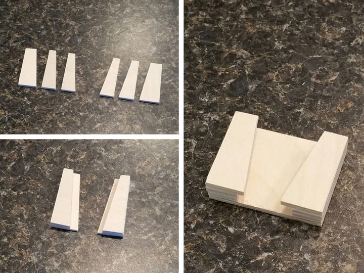
For the female piece, I took a similar approach, making a rectangle to hold the sides that will encase the male piece. Again, a double layer for the smaller side pieces, and it’s all white-glued together:

Note: It was necessary for me to test fit the male piece a couple times prior to cutting and gluing the rectangle for the female piece. You want it to close up perfectly.

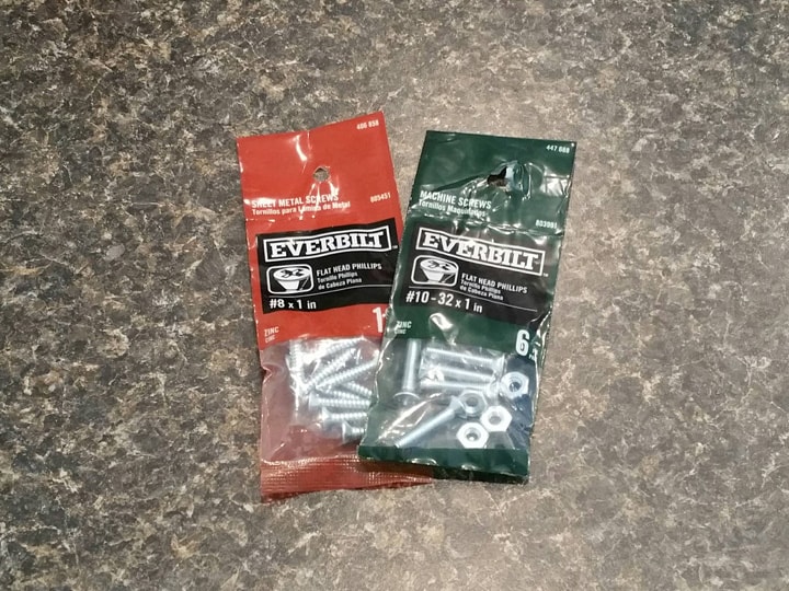
At this point I planned out my mounting hardware:

  • #8 x 1" flat head pointed screws

  • #10-32 x 1" flat head screws & nuts

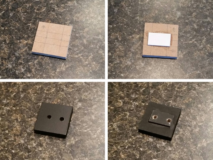
The V-hook is mounted to a square base plate, so I made one out of leftover 1/4" MDF. Deciding that the base plate needs to be bolted into the T-nuts of the sidewall, and determining that there should be a layer of plastic between the two foam strips on the gun mount, I went through the following steps:

  • Marked the base plate for the hole location, with lots of test fitting and measuring.

  • Glued on a small strip of sign plastic (2 layers to make it about 1/16") with epoxy.

  • Drilled the holes and painted black.

After painting the heads of the #10-32 x 1" bolts black, it was a simple matter to screw the base plate into the existing T-nuts in the gun box sidewall.

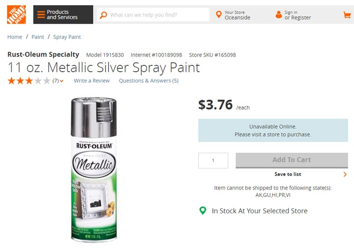
Next, I picked up some metallic silver spray paint from Home Depot:

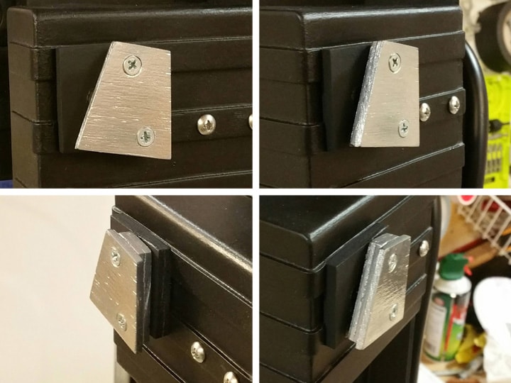
On the V-hook parts, I pre-drilled my mounting holes and counter-sank them (it’s hard wood). Then I painted them, to kind of give them the look of metal. There’s still a little wood grain, but they still look pretty good.

After the paint had dried, I epoxied the male V-hook part to the base plate in the right position, again using Stefan’s plans for guidance. The epoxy held it in place so that I could screw it into the base plate, using the #10 x 1" pointed screws. This not only secured the V-hook very tightly to the gun box (all the way into the sidewall), but also ensured that the layers of wood in the V-hook are held together tightly.

All done! This hook is not going anywhere. It is secured with glue and bolts to the gun box sidewall, which is similarly secured to the motherboard. Strong enough to support a proton gun!

The female V-hook piece I have set aside for attaching to the gun later, when I get to that point.

Next post, I’ll maintain my focus on this area of the pack and complete the rounded corner plate. I also have some reshaping of my motherboard to do here. :slight_smile:

Thanks for reading,

Bill

RUNNING PARTS COST:

$2.29 - Revell Baltic Birch plywood, 3mm x 12" x 4" (Michaels)

$3.76 - Rustoleum metallic silver spray paint (Home Depot)

$0.98 - #8 x 1" flat head pointed screws (Home Depot)

$0.98 - #10-32 x 1" flat head screws & nuts (Home Depot)

$205.17 - previous total

$8.01 - this stuff

TOTAL: $213.18

This build is so fun to watch unfold.

10/10. :mrgreen:

17. CORNER PLATE

The last bit of “cosmetic plating” in this build is the upper right corner of the pack, between the gun mount box and the crank generator. On my motherboard, I failed to round the corner enough, so I will sand it to a larger radius and glue on a corner piece.

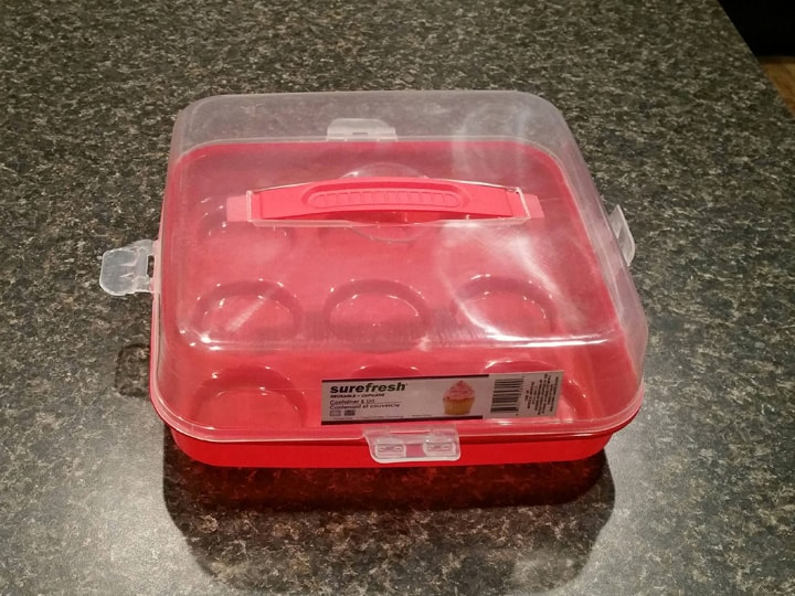
After much searching for viable wood options (I don’t have a router), I ended up back at the dollar store, where I found this plastic cupcake storage container:

Turns out the lid on this thing has a seam that runs around the entire lid, at just about the right height for my corner piece to be just under 3/4" thick. I took the piece through the following steps:

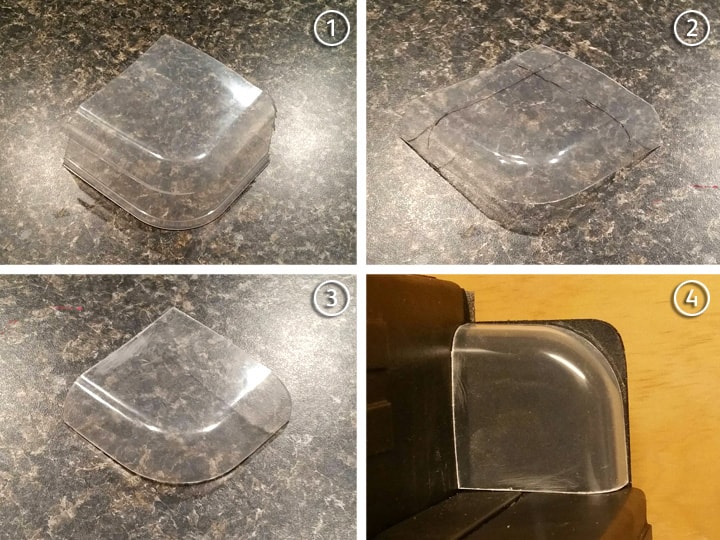
  1. I cut an oversize corner from the container lid. I’ll get four chances!

  2. I cut along the seam at the right height, and marked (from test fitting) where the cut lines will be.

  3. I cut along the cut lines.

  4. I test fitted on the proton pack. I also marked an outline on the motherboard where I will need to round the corner further.

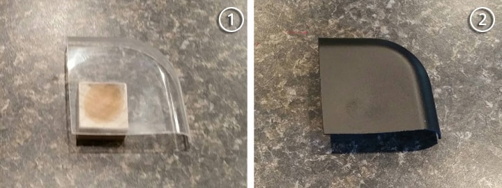
So far, so good. To attach this to the pack, I realized I’ll need more than just these edges. So I took a piece of leftover 1" square dowel, and cut an 11/16" length, using epoxy to glue it to the inside of the corner. Then I painted it black.

Next, time to sand that corner. I used 80-grit sandpaper with a sanding block to first sand a 45-degree angle, and then smoothed it further. I finished with 220-grit and 400-grit afterward.

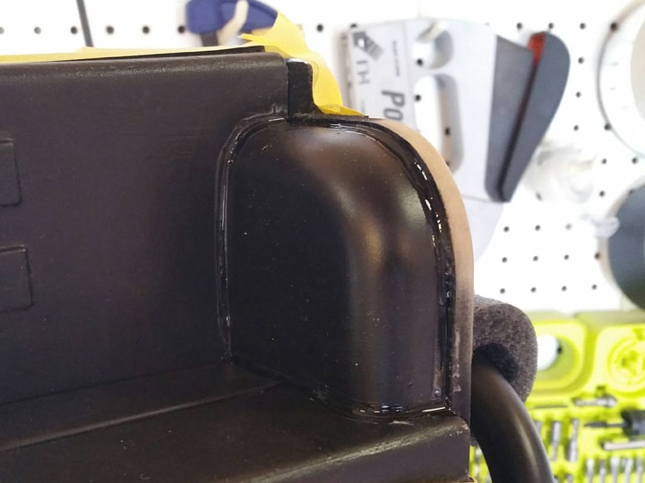
Then, I used epoxy to glue the corner to the motherboard. I realized that the edges weren’t lining up correctly on the motherboard (the plastic of the lid wants to “flare out” a bit), so I used a little epoxy to try to make it stay in place. There were gaps also, so I used a thin bead of superglue (I always use the gel-like blue cap Gorilla Glue) as a “caulking” along the edges.

Regular caulk would have been far too bulky, so this little bit helped.

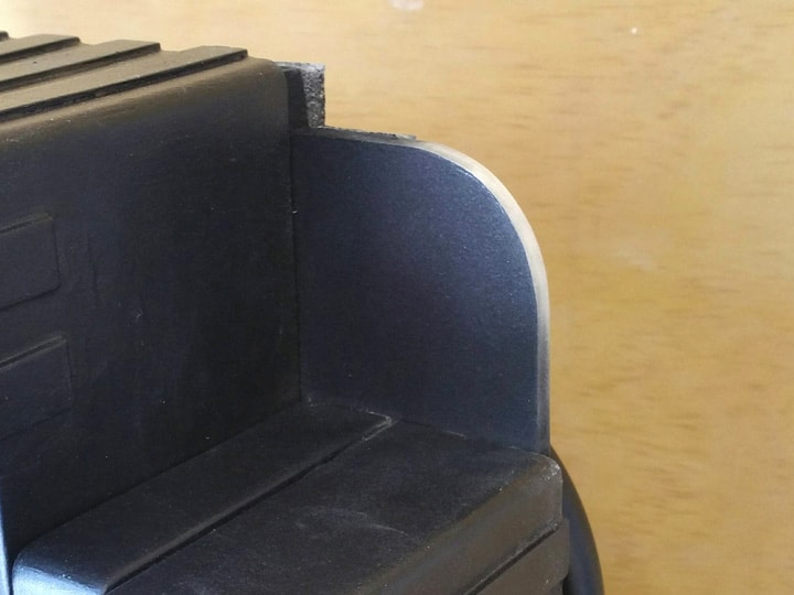
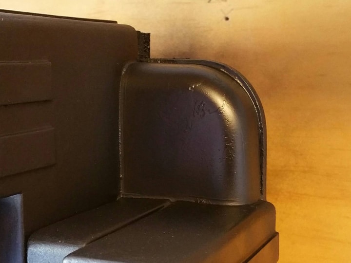
Once I marked off everything and repainted the corner (and the sanded motherboard corner), it now looks like it belongs. :slight_smile:

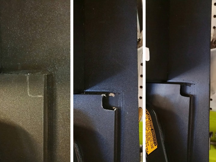
Yep, there’s a little peeled paint there up in the corner. Sanding my imperfections made the paint want to peel off the plastic, so I just painted over it and will call it “weathering.” :slight_smile: Besides, it’ll mostly be overed by other stuff anyway. I’m happy.

Next post, I will tackle a decent looking HGA, for only two dollars and the leftover materials I’ve already used in this build!

Thanks for reading,

Bill

RUNNING PARTS COST:

$1.00 - Plastic cupcake storage box (dollar store)

$213.18 - previous total

TOTAL: $214.18

18. HGA

The Hydrogen Gas Actuator is the final piece in the upper right quadrant of the proton pack. It’s a tube that projects sideways off the crank generator, and has some pretty cool side-facing details. I was able to build this piece mostly from scraps left over from earlier in the build, plus two bucks’ worth of new hardware.

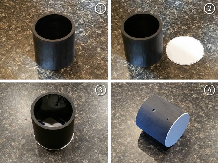
First, the diameter of the HGA is 2-3/8", which is the same outside diameter of the piece of ABS pipe I used when I made the synchronous generator/spacer. So grabbed the pipe and took it through the following steps:

  1. Cut the ABS pipe to a length of 2-1/2".

  2. Traced the diameter onto a piece of sign plastic, and cut it out oversized.

  3. Glued the plastic onto the pipe.

  4. Sanded the flat plastic down till it was flush with the pipe, drilled a hole for the “Legris” elbow screw, and marked a hole for the brass elbow.

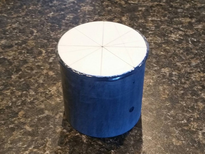
Next, I carefully marked the center and figured out where the top screw holes will be.

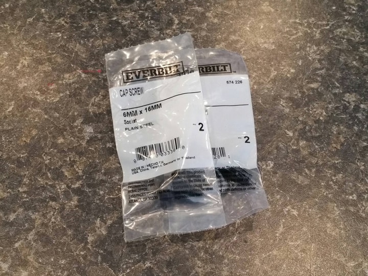
Then, I picked up four 6mm x 16mm socket cap screws from Home Depot.

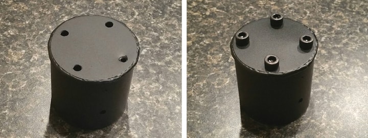
After this, I used hot glue to give the top a “weld” effect (similar to what I did for the N-filter), this time making sure to keep the hot glue from layering onto the top surface. I sprayed it black using the usual formula, and drilled the screw holes. I then inserted the cap screws, securing them with epoxy on the inside.

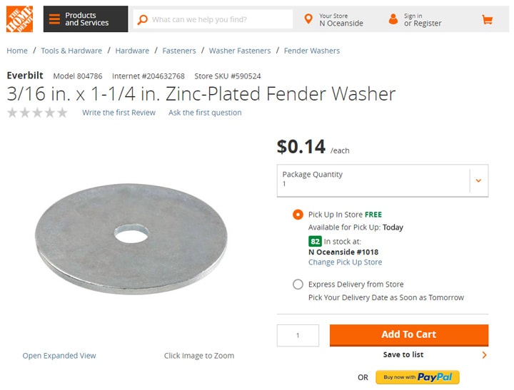
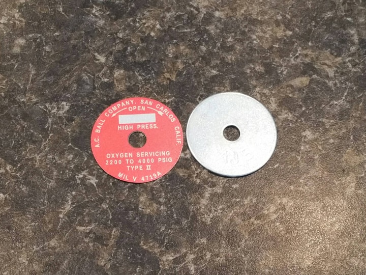
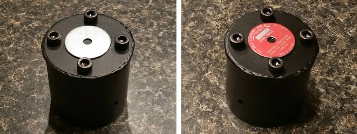
For the center label, I needed a thin, raised metallic disc. Rather then use plastic, I took a hint from one of the forum posts, and picked up a 3/16" x 1-1/4" fender washer from Home Depot:

The diameter of this washer matches my label perfectly.

I cut the label out from the metallic sheet with sharp scissors, VERY SLOWLY. So slowly, in fact, that it took a good 2-3 minutes to cut it out fully. It came out great, but this label sheet has two, just in case. :slight_smile:
I also punched out the center circle with a brand new hole punch (the traditional kind in the school supplies section).

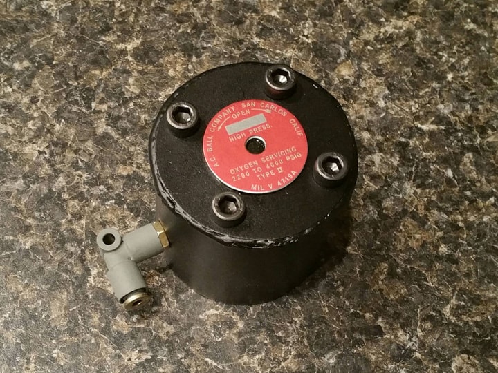
Then, I glued the washer onto the HGA with a small amount of epoxy, and stuck the label on very carefully in the correct orientation.

Next, I attached the plastic “Legris” elbow I had made using the screw and nut, as explained previously.

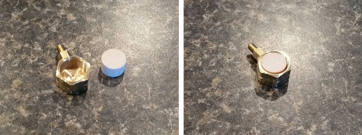
For the brass elbow, I knew I needed something more substantial to anchor it to the HGA than just that thin rim of brass. So I took a piece of leftover 1/2" dowel (from making the crank knob), cut it to the right length, and epoxied that into the brass fitting.

After this, it was a simple matter of using epoxy to glue the fitting to the HGA, using the little hole as a guide for centering. I had to hold it in place by hand until the 5-minute epoxy cured.

To prep the pack for receiving the HGA, I marked and cut the excess bits of foam strips on the side of the crank generator, per some of the guidance from Sean Bishop’s plans.

I also used a little black brush paint on the exposed white foam, just to make sure that no white shows when I glue on the HGA.

Finally, I glued the HGA onto the crank generator, again using epoxy. The HGA is mounted with a slight upward angle in order to allow sufficient clearance for tubing over the gun mount box, as shown on some of the screen-used packs.

All done! I couldn’t be happier. This is my new favorite piece on the pack, and it was fun to make.

Okay, that upper-left quadrant of the pack is staring me in the face. Time to take on the monstrous EDA box and attenuator!

Thanks for reading,

Bill

RUNNING PARTS COST:

$1.00 - 6mm x 16mm socket cap screw (2-pack) (Home Depot)

$1.00 - 6mm x 16mm socket cap screw (2-pack) (Home Depot)

$0.14 - 3/16" x 1-1/4" fender washer (Home Depot)

$214.18 - previous total

$2.14 - this stuff

TOTAL: $216.32

19. EDA (BODY)

The Electrostatic Dissipation Assembly (EDA) and attenuator take up the majority of the upper-left quadrant of the proton pack. This big boxy shape serves as a base for the booster, booster frame, and various details. I am making both EDA and attenuator together, but it made more sense to break this part into three steps: The EDA, the attenuator, and the assembly and finishing.

This build is slightly more expensive than others, mainly because of all the no-parking sign plastic I went through in order to give it sufficient stability. Regardless, this is a pretty short post, because most of the techniques are outlined in previous posts. No need to repeat every detail!

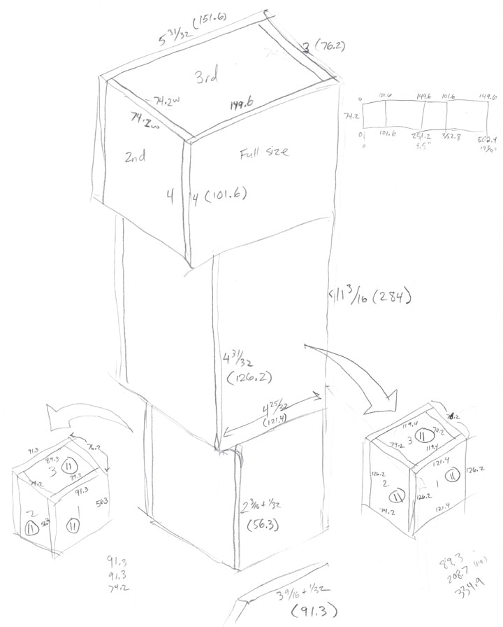
After taking some measurements of the remaining space on my pack, consulting many photos, and reviewing Paranorman’s/Stefan’s/Bishop’s guides, I came up with this sketch. I don’t expect it to be of much use to anyone else, but it helps show my thought processes in how I laid out all that plastic:

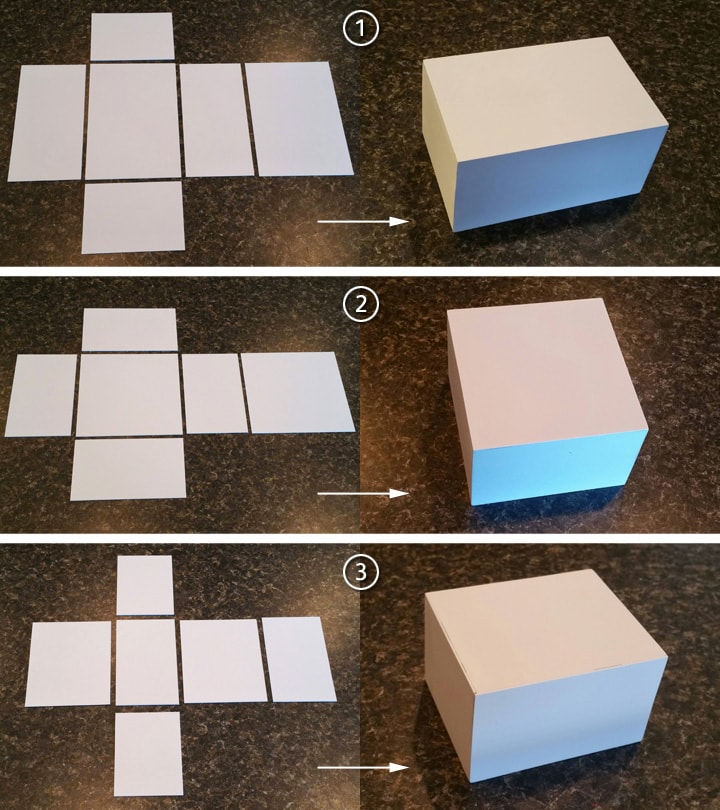
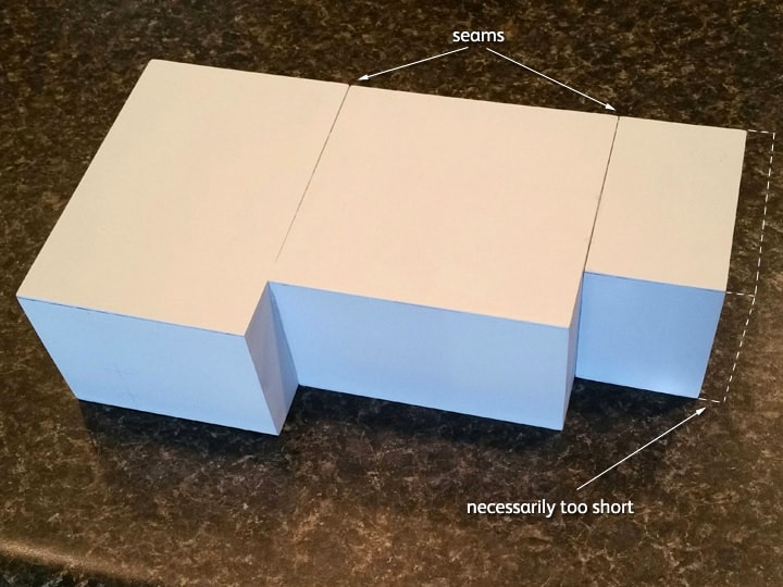
First, I built three separate boxes out of no-parking sign plastic:

  1. Top box is 5-31/32" x 3" x 4" high.

  2. Middle box is 4-25/32" x 3" x 4-31/32" high.

  3. Bottom box is 3-19/32" x 3" x 2-7/32" high.

Next, I glued all three boxes together with epoxy to form the EDA box:

A couple thoughts at this point:

  1. Why three separate boxes? Sure, I could have tried to build the box as one large piece, but doing it in pieces was not only less complicated, but it also adds a significant amount of reinforcement and stability to the whole thing. This will become more important when the booster is mounted to the box.

  2. Notice that the smallest box on the bottom seems a bit too short? Yep, it’s too short by half an inch. This was necessary because of some of the limitations in using Paranorman’s motherboard with Stefan’s center cover. If I were to start over, I’d probably have tried to make Stefan’s motherboard, but I don’t think it will cause any problems here.

  3. Notice how wide those seams between the boxes are? This is caused by the fact that my three boxes are not 100% perfectly square. When I glued them together, I made sure that the front and right side of the EDA box was perfectly flat; I pushed all three boxes, face down, against a right angle wall as the epoxy cured. This caused some angling away of a few of the surfaces that weren’t square to each other.

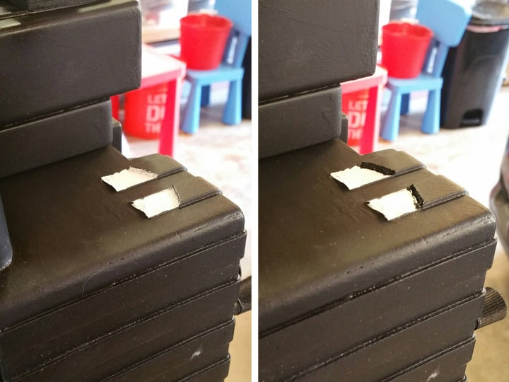
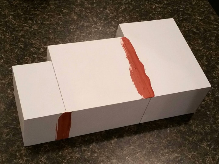
To correct for this, I filled all of the seams with Bondo spot putty. I was going to do this anyway, because the EDA is supposed to look like one full piece. I just didn’t expect a full 1/16" gap in some areas. The putty worked for the most part.

(By the way, I prefer this putty over others in this case, because it sands so much more easily. But it is also more prone to cracking, so I had to be very careful. Once painted, it’s not so brittle.)

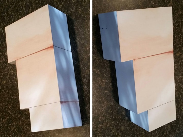
I only needed to clean up two seams, as the rest are covered by the pack or attenuator.

After the Bondo spot putty application and some light sanding, my EDA box was complete.

Next post, I’ll build the attenuator. The post after that, I will assemble it all, finish and detail it, and mount it on the pack.

Thanks for reading,

Bill

RUNNING PARTS COST:

$5.38 - 19" x 15" Handicapped Parking sign (Home Depot)

$5.38 - 19" x 15" Handicapped Parking sign (Home Depot)

$216.32 - previous total

$10.76 - this stuff

TOTAL: $227.08