Astyanax's Low-Budget mostly-Gagnon (Paranorman) Scratch Build (pic heavy)

20. ATTENUATOR (BODY)

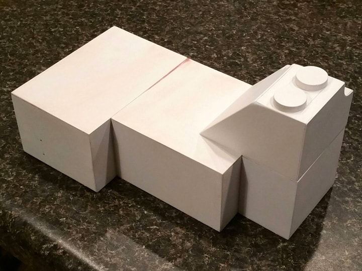
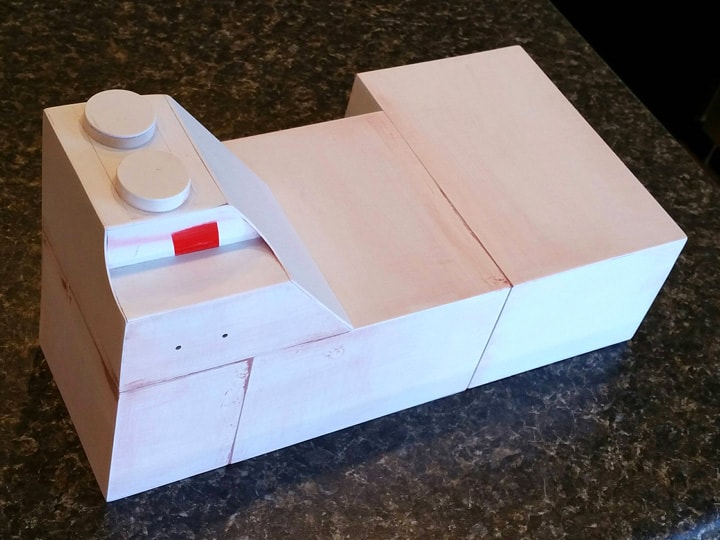
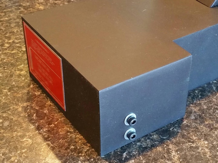
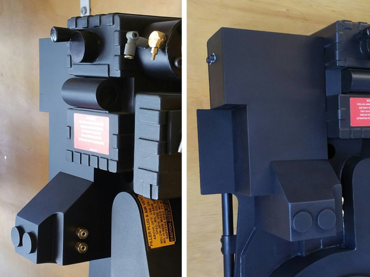
The attenuator attaches to the lower section of the EDA box. It is joined in a way that should make it all look like one piece. I came close enough!

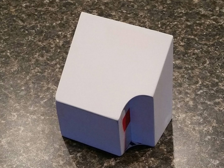
In the steps below, you can see my build process. The most difficult aspect is that the curve that is provided for the PPD is recessed a bit, so there have to be some “inside walls”.

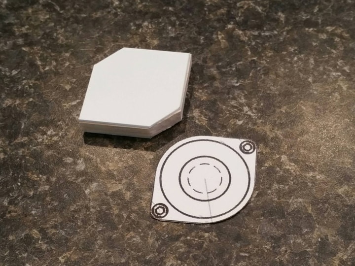
  1. I cut the base plate according to Stefan’s guidelines and my own EDA box dimensions. The rounded notch was traced using a piece of 1" inside diameter PVC pipe, which will later serve as the PPD. It was cut with curved lexan scissors and sanded.

  2. I glued on the back plate.

  3. I measured, cut, and glued the left wall.

  4. I measured, cut, and glued the smaller right wall.

  5. The middle wall provides that “inside wall” for the PPD. It is a copy of the left wall.

  6. The remaining part of the “inside wall” is a small piece between the middle and right walls.

  7. I measured, cut and glued the front wall.

  8. Finally, after some sanding, the angled top wall was completed. The curved notch was shaped using the 1" ID PVC pipe with some sandpaper wrapped around it.

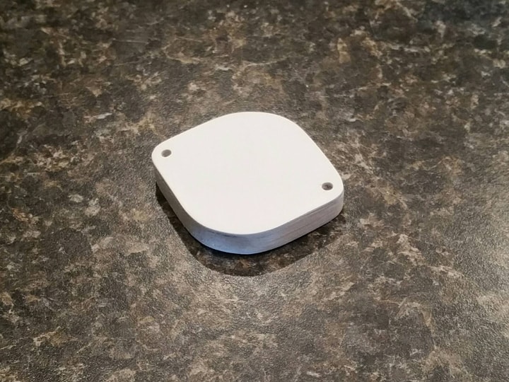
Then, I carefully sanded the whole thing, cleaning up seams and overlaps, and rounding the corners slightly.

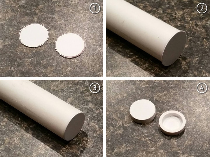
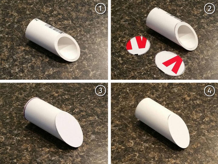
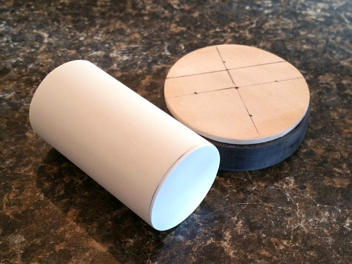
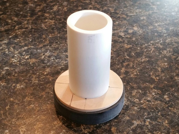
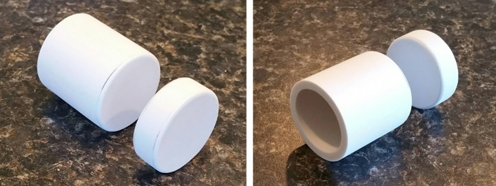
To make the two “discs” for the front, I used the same process as I had for the vacuum pump, only with a smaller piece of PVC pipe. 3/4" inside diameter PVC has an outside diameter of 1-1/16", which is close enough to the 1-1/8" dictated by Stefan.

I then traced the end of the pipe on leftover sign plastic, superglued it on, sanded it clean, and then sliced it off at under 1/4" to make the discs.

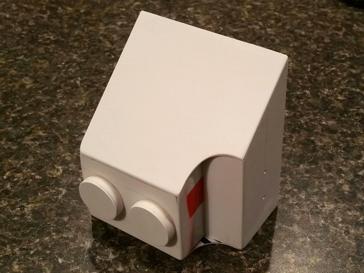
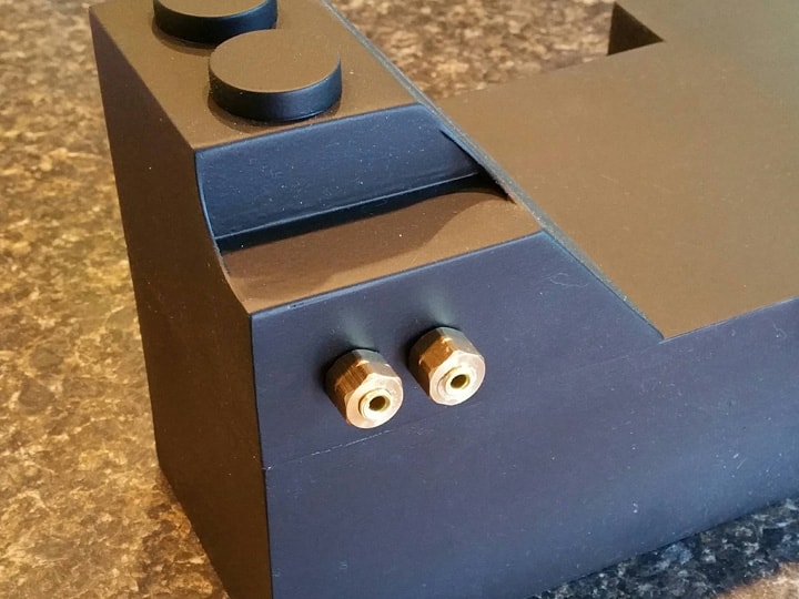
Finally, I carefully marked where the discs are positioned, and glued them onto the attenuator. It’s hard to tell from the picture, but I also marked and drilled with a tiny drill bit the two holes for the brass connectors that will go in the right side.

Next post, I will assemble, paint, and detail the EDA/attenuator component.

Thanks for reading,

Bill

RUNNING PARTS COST:

$1.24 - 2’ x 3/4" PVC pipe length (Home Depot)

$227.08 - previous total

TOTAL: $228.32

You are doing some amazing work!! I look forward to every single one of your informative updates.

Wow, thank you so much, I really appreciate that. Kinda makes it worth going through all the documentation work. :slight_smile: I really hope some people get some benefit from this, even if it means just helping folks understand where all the parts or labels go. :slight_smile:

Next post coming in minutes!

Bill

21. EDA/ATTENUATOR ASSEMBLY, FINISHING & DETAIL

Time to finish this beast.

First, I glued the attenuator onto the EDA box using superglue.

As before with the EDA box pieces, there are some unusual seams and slight misalignment. I corrected the misalignment with some heavy sanding (80-220-400 as usual), and attempted to fill all the seams with another round of Bondo spot putty.

This worked for the most part, but there are still some minor seam lines in a few places that I wasn’t able to fully fill. But after painting, I think it looked great. :slight_smile:

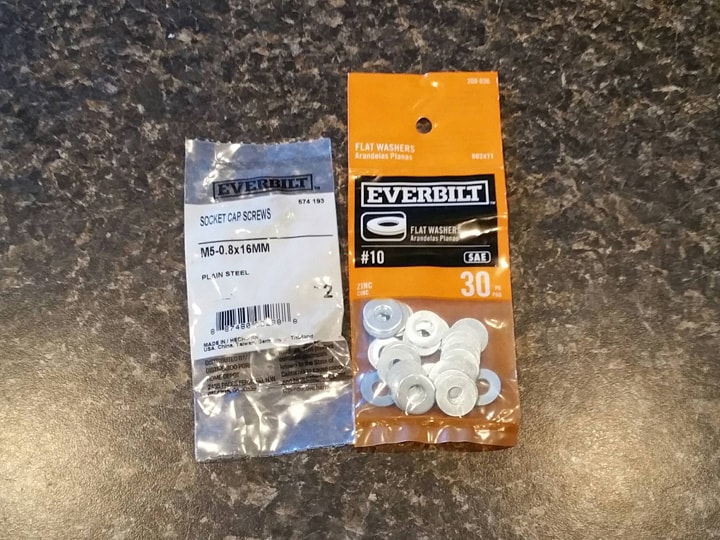
The EDA has a couple of screws on its left side. As is shown in some online pics, I opted for some 5mm socket cap screws and #10 washers:

The two spots I had marked previously with tiny drill holes I now enlarged to 3/16". I was able to screw in the cap screws carefully, and they went in nice and tight, no glue necessary!

I also applied the large metallic label that goes on the top of the EDA.

The two brass “Legris” straight connectors I made previously go on the right side of the attentuator. I enlarged those holes to 3/16" also, and I was able to pop the fittings right in. They held tight, again no glue necessary!

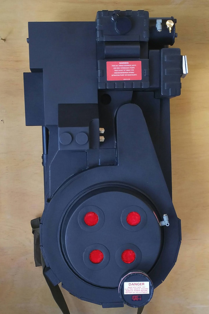
Finally, I glued the entire assembly onto the pack, using E6000 for the most part, with hot glue in the corners to anchor it while the E6000 cured.

Starting to look like a real proton pack now!

Next post, I’ll make the PPD.

Thanks for reading,

Bill

RUNNING PARTS COST:

$0.65 - M5-0.8 x 16mm socket cap screws (2-pack) (Home Depot)

$0.98 - #10 washers (Home Depot)

$228.32 - previous total

$1.63 - this stuff

TOTAL: $229.95

It’s the home stretch! Love your ideas and your paint looks great!

I absolutely love watching this thread.

You have obviously done a lot of homework. The instructions are clear, the photos are fantastic, and the running cost at the bottom is icing on the cake. And - it’s looking great!

I’m thinking a crunch bar should be kept around for when this gets finished. 'Cuz you- you’re earning it.

22. PPD

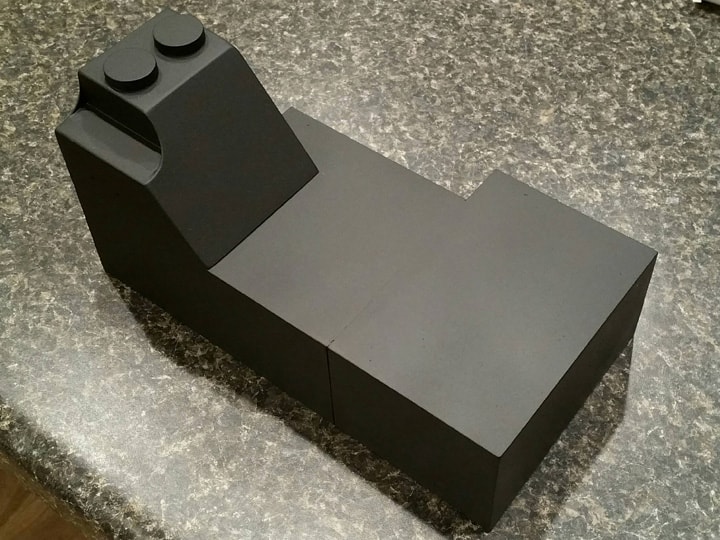
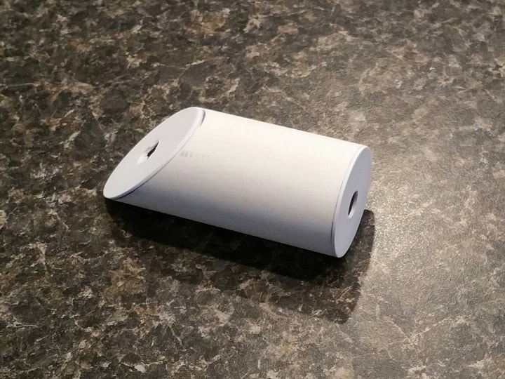
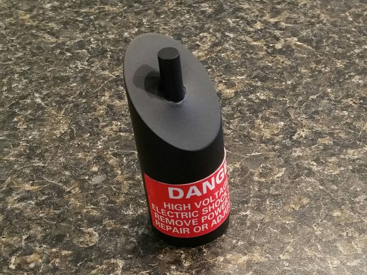
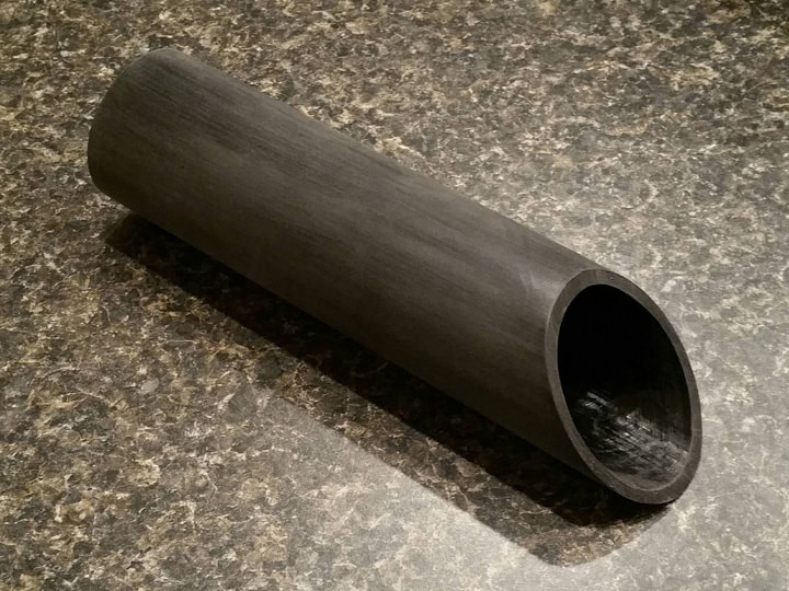
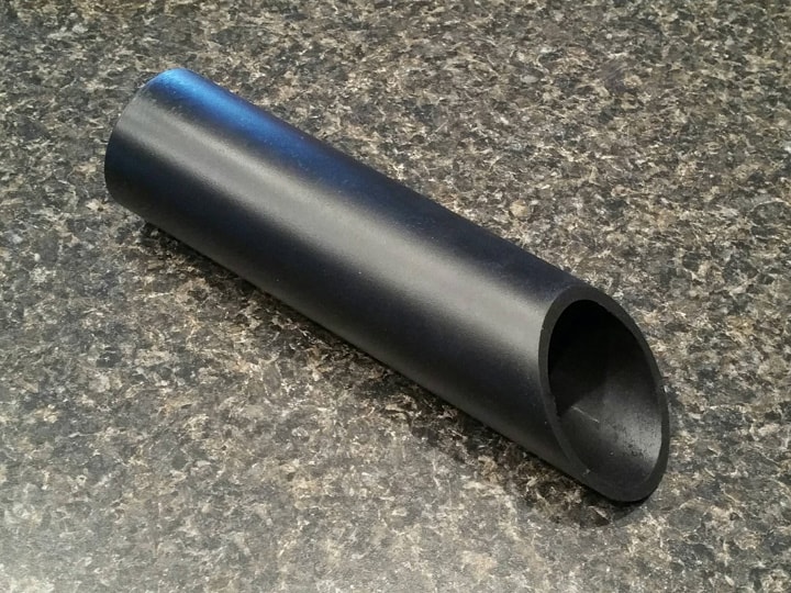
The Primary Power Distributor is a smallish tube with an angled top, which lives in the notch of the attenuator. Lucky for me, I still have plenty of the 1" inside diameter PVC lying around, so making it was nearly free!

I won’t explain yet again the details of putting caps on PVC pipes, but that’s pretty much what I did, after cutting it to Stefan’s specs:

After smoothing the piece, I drilled a 5/16" hole all the way through.

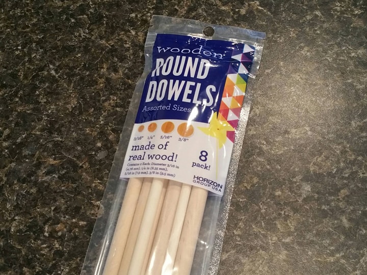
I picked up these assorted 12" dowels from Wal-Mart for under two bucks. These will come in handy throughout the rest of this project.

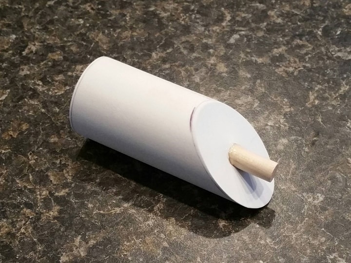
I cut a 5/16" dowel to about 3-1/2", and glued it into the PVC pipe, making the bottom flush. This will give it a little bit of nice detail underneath, and help hold the tubing boot at the top.

Then, I painted the piece black, using the usual formula.

After that, I cut out the medium-sized “Danger” label from the non-metallic sheet, and affixed it to the PPD with spray adhesive.

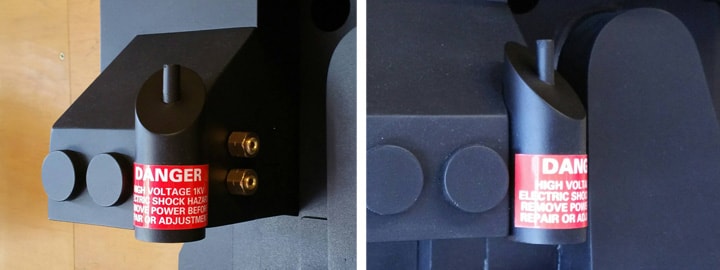
And finally, I glued the PPD to the attenuator with epoxy.

It’s rotated a few degrees too far counter-clockwise, but I don’t mind. :slight_smile:

Done with an easy part. Next post, I will make and mount the booster.

Thanks for reading,

Bill

RUNNING PARTS COST:

$1.67 - Assorted dowels (Wal-Mart)

$229.95 - previous total

TOTAL: $231.62

23. Booster

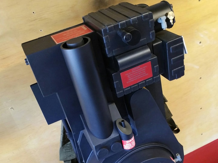
The booster tube is that large vertical tube on the EDA box. I was able to build this very cheaply, using only leftover parts from previous components plus a soda bottle!

First, I measured my needed dimensions on the pack and cut a length of 2" inside diameter ABS pipe (left over from the synchronous generator and HGA). This pipe has an outside diameter of about 2-3/8", which is perfect for this part.

Using a leftover piece of sign plastic (from when I cut the sides for the attenuator) I was able to determine the exact angle of the attenuator slope to EDA wall (in my case 131 degrees), and cut the sloped end of the booster tube to match. I gave it a light sand to take off the sheen so that paint will stick better:

I then painted the large tube using the usual combination.

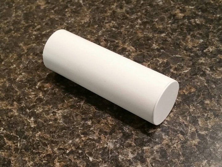
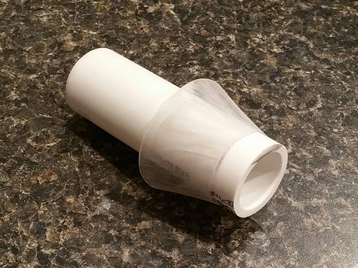
For the booster plug (the smaller inner tube), I used a 4-inch piece of leftover 1" inside diameter PVC pipe, capped on one side with sign plastic as I’ve done in previous posts above:

Now, the dilemma: how to mount the smaller tube into the flat end of the larger tube so that it’s centered (kind of floating between walls), extends past the large tube about a quarter inch, and ends only a few inches deep? The plans call for two inches’ or so worth of open depth, and I shouldn’t be able to see the bottom.

I noticed some users built custom rings or blocks out of wood, but I’m not that handy with wood. Instead, I opted to use a custom “funnel” approach, starting with this:

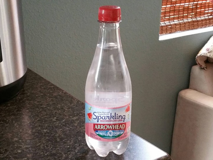
This Arrowhead seltzer water comes in six-packs, so a single bottle costs about fifty cents or so. I chose this style of bottle because of its long, sloping neck, which is quite necessary (most plastic soda bottles these days have much more stubby necks).

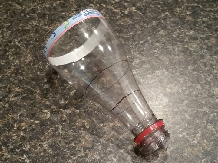
After cutting the bottle in half, I inserted the smaller PVC tube into the back of the neck and marked where it touches. I then inserted the mouth of the bottle into the larger ABS tube until the neck touched those walls, and marked that as well. I was left with a piece that has these two marks:

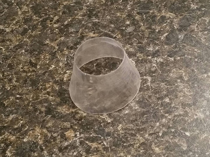
I then cut the bottle at those two marks and lightly sanded it, resulting in this funnel shape:

Next, I superglued the small end of the funnel over the small PVC tube at its back end.

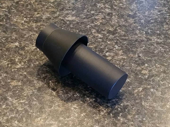
And then I painted this funnel assembly black.

To mount this into the booster tube, I laid a bead of superglue inside the large tube about two inches deep (eyeballing it), and inserted the funnel assembly until the top of the plug was about 1/4" above the rim of the booster tube. I held it centered for a few seconds until the superglue engaged. The plug is done!

I then mounted this on the EDA box of the pack, using a thin bead of epoxy on the EDA wall, and a VERY thin layer of epoxy on the rim of the sloped end of the tube.

Booster, check. With each part completed, I’m starting to get more excited!

Next post, it’s time to take on the power cell. I will be putting some cheap lights in it. :slight_smile:

Thanks for reading,

Bill

RUNNING PARTS COST:

$0.50 - Arrowhead seltzer bottle (grocery store)

$231.62 - previous total

TOTAL: $232.12

24. POWER CELL (with lights)

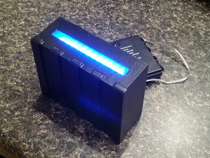
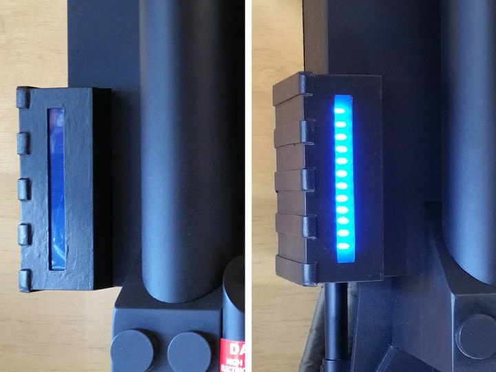
The power cell is a simple box that lives on the left side of the EDA box, and contains a cycling blue light strip. I wanted to put some cheap lights into the box in this step. :slight_smile:

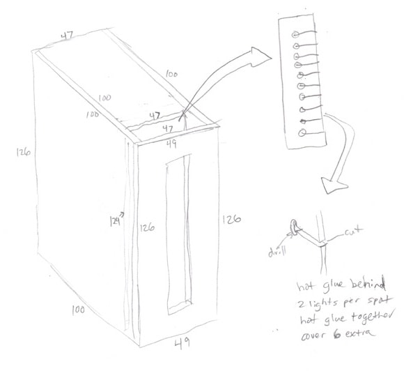
First, my sketches and dimensions, after measuring what space I had left on the motherboard.

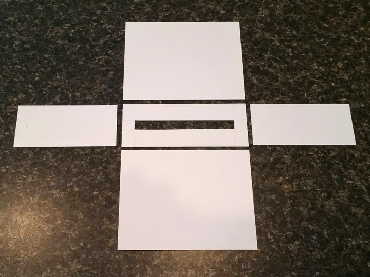
I made the box itself out of leftover sign plastic, cutting the slot in the front for the lights, and leaving the back open.

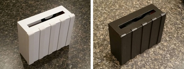
After assembly, I sanded the box and applied the craft foam strips, similar to how the gearbox/crank generator was made. I then painted it with two coats of white glue, and painted it black.

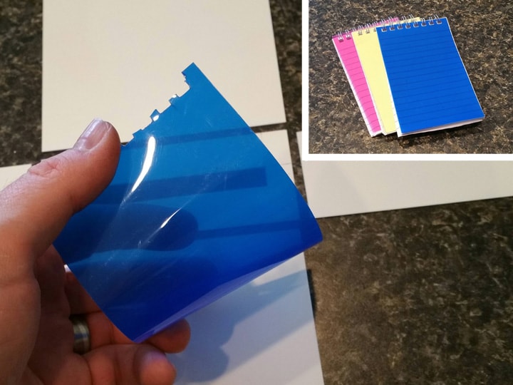
For the blue light cover strip, I found some mini notepads at the dollar store with nice clear plastic covers. They come in a three-pack, and the blue was perfect for this application.

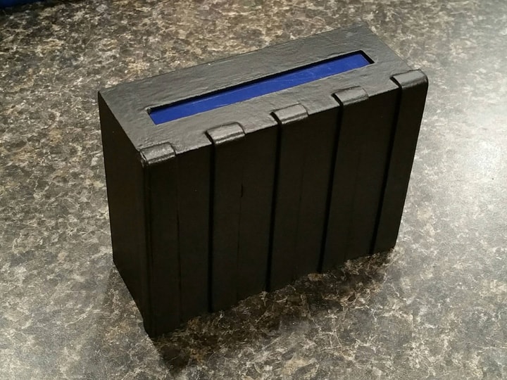
I superglued a rectangle of the blue plastic on the inside of the box.

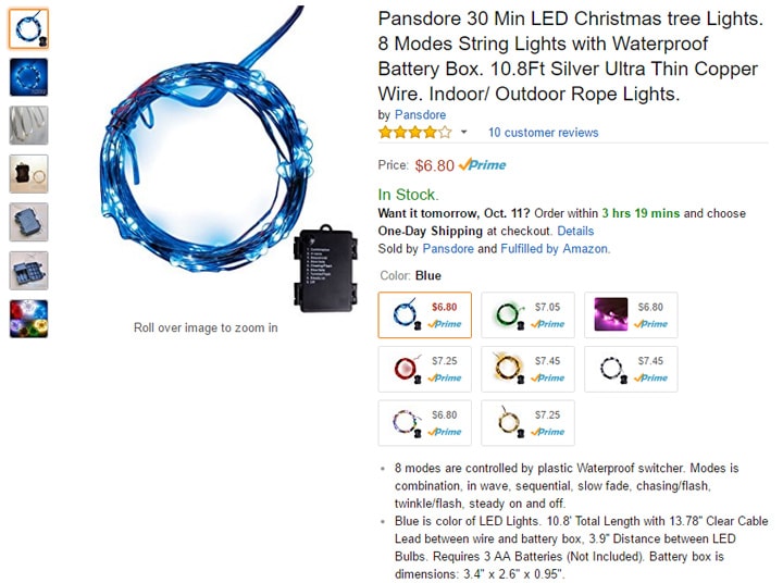
For the lights, I purchased a blue set of 30 mini LEDs on Amazon.

These are exactly like the red ones I used on the cyclotron, in that even though there are different blink patterns available, they all blink at the same time. I’m okay with this, considering the price, and I found a blink pattern I was happy with. They are quite bright!

image

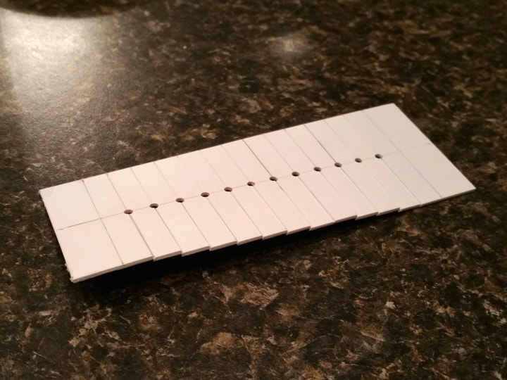
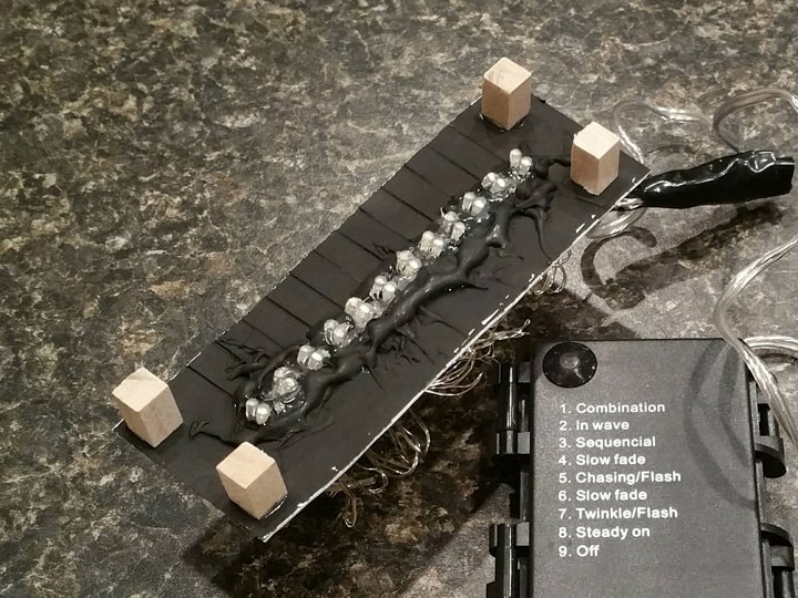
To mount the lights in the box, I first had to align them. So I took a piece of sign plastic, cut it to almost the same size as the front panel of the box, marked some measurements, and drilled 12 holes vertically in the center. I also sliced a straight line right up to each hole, so that the LEDs could be inserted.

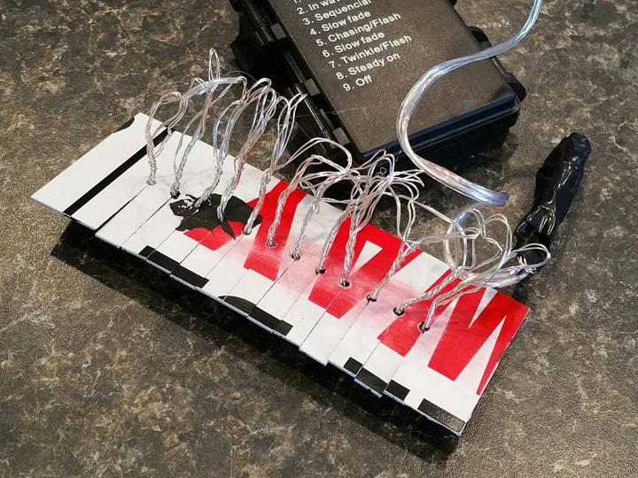
I then twisted the LEDs into pairs (12 pairs, 24 lights total), and covered the remaining 6 with black electrical tape. Each LED pair I inserted into a hole (using the slice to help move it to the hole).

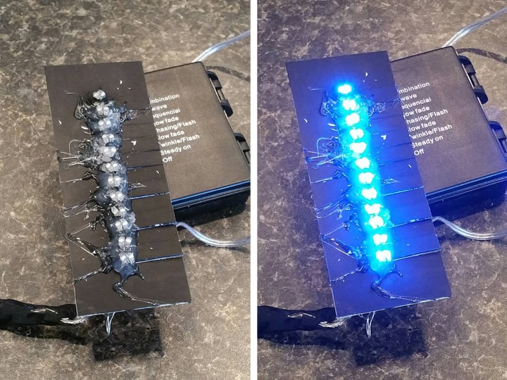
On the front side, I secured each pair with hot glue. I was careful to hold the LED pairs in just the right spot and orientation as the glue cooled.

I then took some leftover square dowel, cut four pieces a half-inch long, and superglued them to the front of the light panel. These serve as “standoffs”, so the lights are a little bit back from the front blue plastic.

After this, I mounted the lights inside the box, using epoxy on the standoffs in the corners.

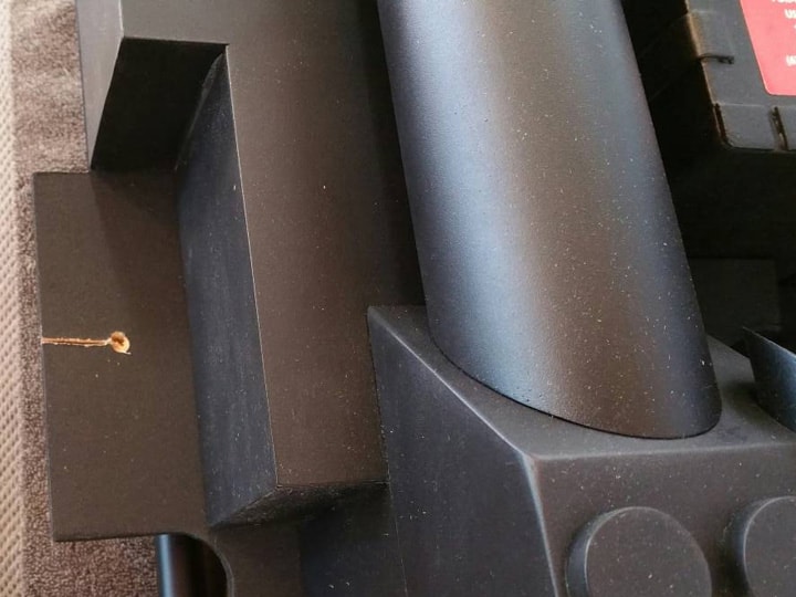
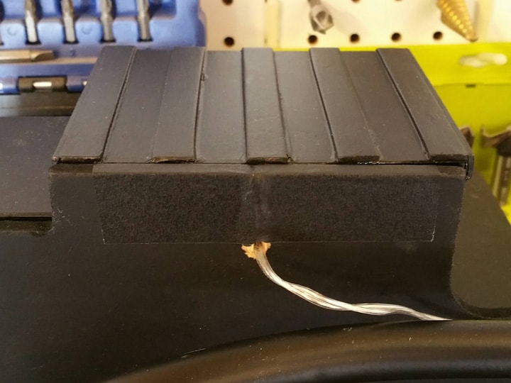
Time to mount on the pack. Even though ideally I should have threaded the light string through a hole in the motherboard prior to mounting them in the box, I needed space to work. So I drilled my hole, and cut a slice with a handsaw so that the cord could be passed through.

After passing the cord through, I used some gaffer’s tape I had lying around to cover the slice. Thankfully, the tape matches the pack’s black paint almost perfectly, and the tape will give it that kind of “used” look. I’m definitely happy with this solution.

I also glued the entire power cell box to the pack at this time with epoxy.

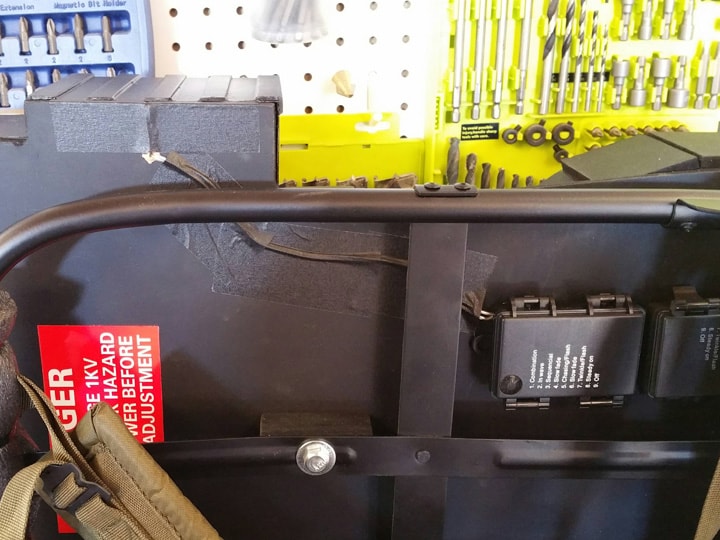
Next, I mounted the control box on the back of the pack, right above where I had mounted the red cyclotron control box. This ensures access to the batteries. I secured it with E6000, and with hot glue in the corners to hold the box in place while the E6000 cured. I also covered the cord with more gaffer’s tape.

The power cell looks like it belongs, and I couldn’t be happier with how the lights turned out! The pictures don’t really do it justice, but having blue lights with a blue plastic “lens” in front, I get a very deep blue color, but also intense brightness.

So that’s it! Next post, I’ll make and attach the injectors.

Thanks for reading,

Bill

RUNNING PARTS COST:

$6.80 - 30 battery-operated blue micro LED string lights (Amazon)

$1.00 - 3-pack mini notepads (dollar store)

$232.12 - previous total

$7.80 - this stuff

TOTAL: $239.92

Excellent and ingenious work!

So clever! Awesome

25. INJECTORS

The two injector tubes protrude downward from the bottom of the power cell. Although they seem like just a couple of PVC pipes, I found that making them look good was a bit trickier than expected.

First off, the diameter of the injector tubes is supposed to be 1-1/2". There is no readily-available size of PVC pipe that matches this outer diameter. A 1" inside diameter pipe is 1-5/16" on the outside (enough to look strangely small), and a 1-1/2" I.D. pipe is significantly bigger.

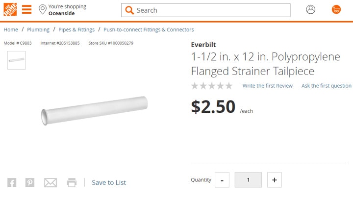
After a bit of thinking and hunting at Home Depot, I found this 1-1/2" (outer diameter) drain “tailpiece” made out of polypropylene, with 12" tailpieces selling for $2.50 each. I needed two, because my injector tubes had to be just over 6" each.

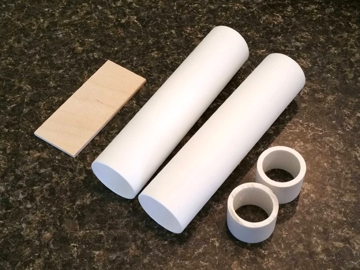
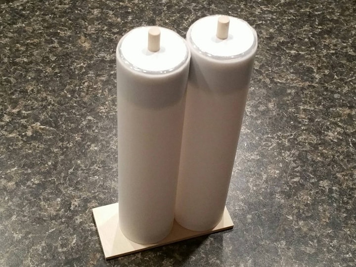
After cutting the tailpieces to about 6-1/2" long (held up to my pack to be sure), I also cut a piece of 1/8" Baltic birch plywood (left over from the V-hook) to a size of 3-5/8" x 1-5/8", and I cut two pieces of 1" I.D. PVC to 1".

A word about the “weld” effect on these tubes. The purpose of these 1" PVC pieces is to aid me in getting a nice weld look on the ends of the tubes. Unlike the HGA and N-filter, it seems from some reference pics that this is more of an “inner” weld, creating almost a beveled effect on the tubes. The 1" PVC slides inside the tailpieces almost perfectly, so these helped me achieve that bevel, as I’ll explain below.

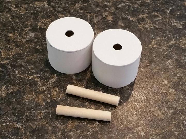
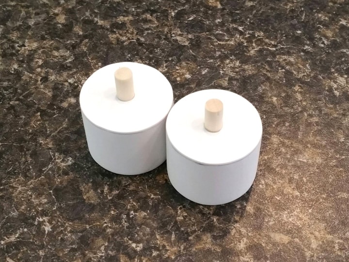
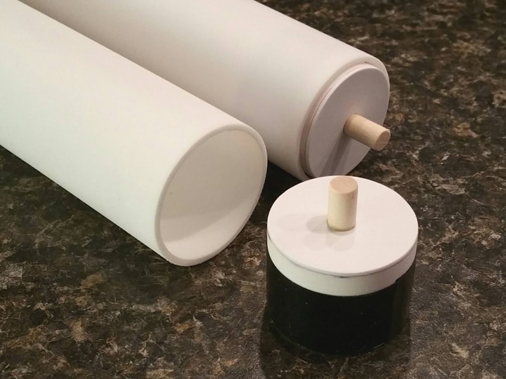
But first, I capped the two PVC pieces with leftover sign plastic, using the superglue-and-sanding technique outlined previously. I also drilled a 1/4" hole in the center of each cap, and cut two 1-1/2" lengths of 1/4" dowel (from the assorted dowels package).

I inserted the dowels into each part so that about 1/2" was sticking out the end. I secured these on the inside with epoxy, making sure they were perfectly vertical. These will give me a surface for the “boots” to hold later when I add tubing.

The PVC slides into the tailpieces, but there’s still about a 1/32" gap all around. I filled that gap by wrapping a couple layers of electrical tape around the lower sections of the PVC pipes. I then glued them into the tailpieces using epoxy, making sure to leave the PVC protruding about 1/8" from the end. This gives me a “stairstep” shape on which to build my beveled weld.

For the weld effect, once again I used hot glue. I’m not a big fan of the sculpted look that uses repeated circles. Just an irregular fill is good enough for me.

It’s hard to tell from this picture, but my hot glue filled the gap nicely, hiding the upper and lower corners. It will become more visible when these parts are painted.

I then glued the tubes together using a very thin bead of epoxy.

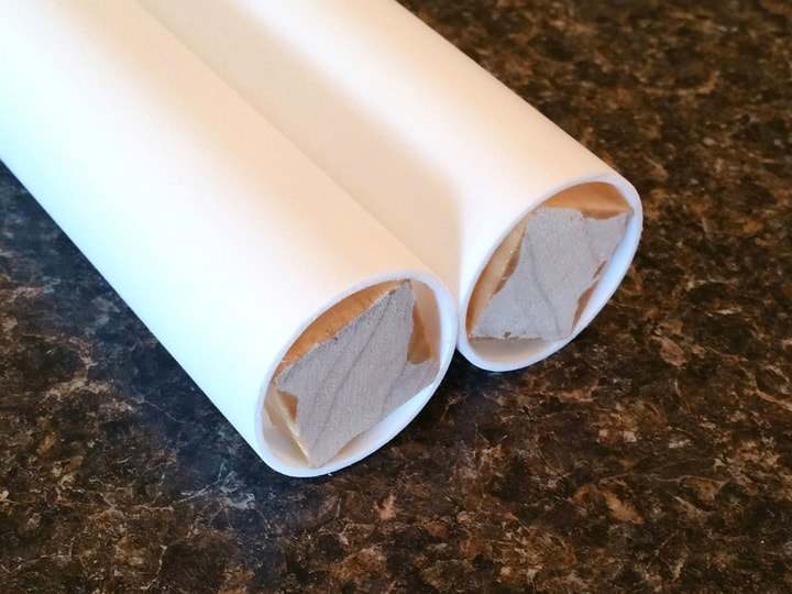
To enable the tubes to really grip their mounting surface, I cut a couple 1/2" lengths of leftover 1" square dowel, lightly sanded the corners, and jammed them into the bases of the two tailpieces. I secured them with epoxy.

Then, using Stefan’s plans for guidance, I epoxied the tube assembly to the piece of plywood. Ready for painting!

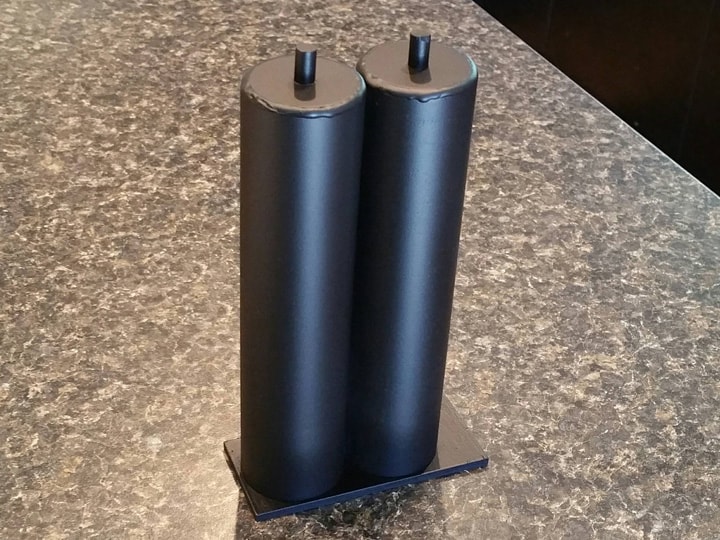
Next, I painted this entire assembly black, using the usual formula. The welds look great!

After the paint had fully dried, I glued this assembly to the pack, using epoxy in the center of the plywood piece, with some dabs of hot glue in the corners to hold it all in place while the epoxy cured.

The final component that is found on many packs is an angled bracket that holds the tubes to the motherboard. This adds stability and durability. I hunted through the Home Depot and Lowe’s inventories looking for something reasonably priced that would fit just right, but came up empty. So instead I decided to make one.

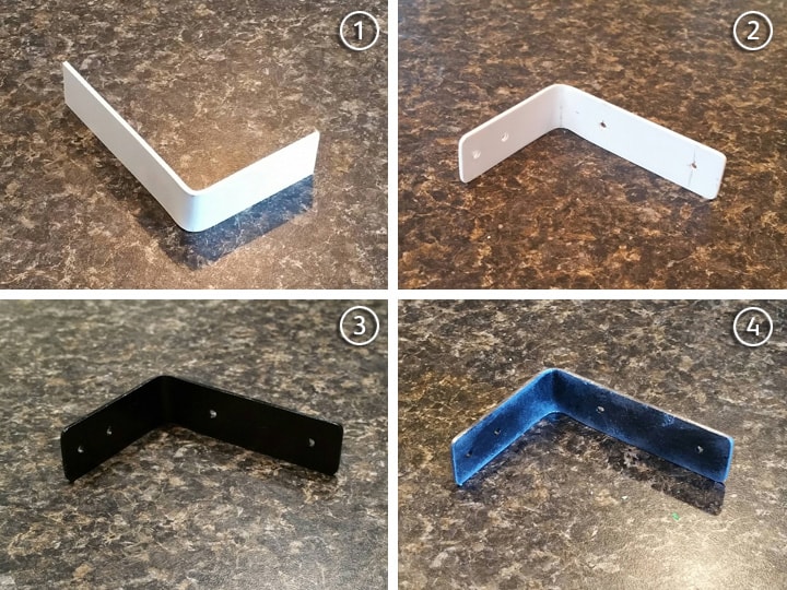
Leftover sign plastic is not as secure as metal, but it should be enough for my needs here. After cutting a piece to about 5" long by 3/4" wide, I bent it after heating it with a heat gun (a hair dryer works as well), until I had a nice 90-degree bend.

  1. I test fit the bracket to the pack, and trimmed it to size.

  2. I rounded the corners, and drilled pilot holes for my screws.

  3. The piece was painted black.

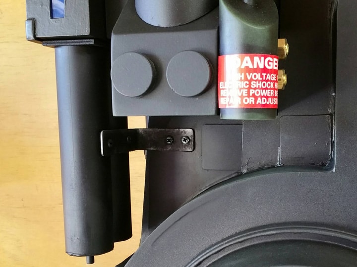
  4. The piece was “weathered”. I use this term loosely, because I still have a lot to learn in this area. Basically my process was to spray silver metallic paint into a disposable cup, and use a piece of foam as a sponge to dab onto the bracket. When I overdid it, I repeated this with the black. And then silver. And then black. Until it sort of looked okay. :slight_smile:

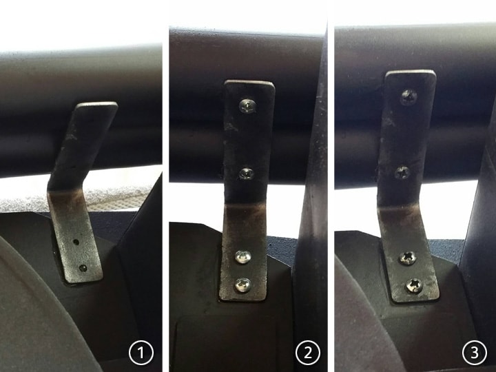
I then mounted the bracket onto the pack:

  1. The bracket was glued to the pack and tubes using epoxy. Some of the epoxy leaked out from under the edge.

  2. I screwed the bracket into the tubes and center cover using leftover #6 x 3/8" screws from my Clippard valve builds (coming very soon–I work on multiple components at a time).

  3. I “weathered” the screws by brush painting some black on them, and sort of wiping it off.

To handle the bits of epoxy that seeped out from under the bracket, I masked off nearby parts and hit the area with a quick blast of flat black. That did the trick.

(The downward angle of the injector tubes is correctly parallel to the rest of the pack. This camera angle makes it look off.)

Not too bad, I can live with this. Especially since it will be mostly obscured by the ribbon cable.

This “bracket” did lend some stability and security to those tubes, so it was the right call. They otherwise felt pretty flimsy with only the power cell to hold them. But I really need to step up my weathering game before this build is done. :slight_smile:

Next post, I’m taking a break from big parts, and will make the discs and vacuum tube on the synchronous generator. After that, scratch-built Clippard valves!

Thanks for reading,

Bill

RUNNING PARTS COST:

$2.50 - 1-1/2 in. x 12 in. Polypropylene Flanged Strainer Tailpiece (Home Depot)

$2.50 - 1-1/2 in. x 12 in. Polypropylene Flanged Strainer Tailpiece (Home Depot)

$239.92 - previous total

$244.92 - this stuff

TOTAL: $244.92

26. DISCS & VACUUM TUBE

On the synchronous generator can be found two stepped discs, as well as a pipe that serves as the other end of the vacuum tube.

I shopped and researched a great deal trying to find matching lids or discs or whatever, and found it too difficult to adequately match the needed sizes. So I decided to make my own with leftover materials!

But first, I wanted to show my process for making a disc, as I have no major power tools (except for a too-small miter saw).

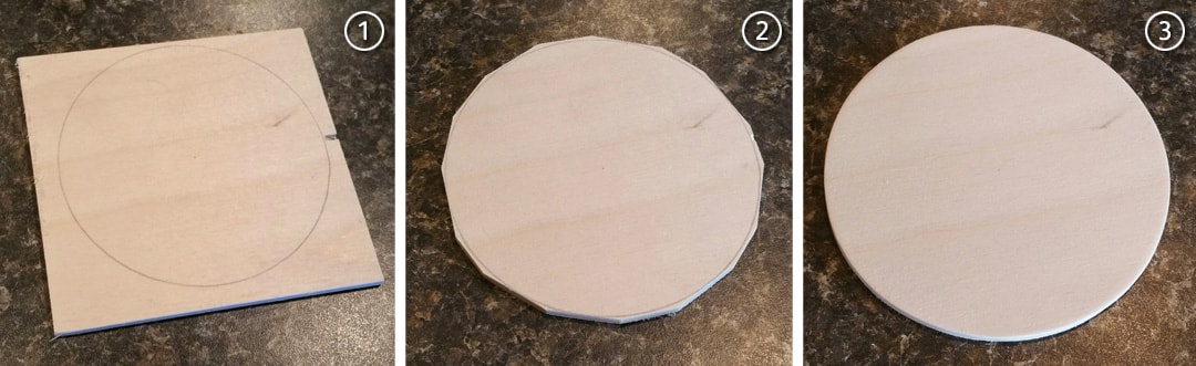
  1. I drew the desired circle on my material using a compass.

  2. Using a miter saw (any saw works), I cut straight lines as close to the circle line as I could get. First, the four 90-degree sides, then the four corners, and then the resulting eight corners from that. The end product is a 16-sided polygon that surrounds the circle.

  3. I sanded the corners off with a sanding block, rounding as I went. It’s not as time consuming as it seems. I used my usual 80-220-400 grit progression.

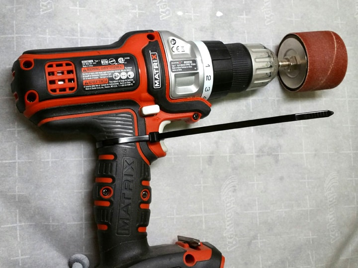
For the larger half-inch thick disc, sanding by hand WAS extraordinarily time consuming. I don’t have a power sander, so I used a sanding drum attachment on my drill, and zip-tied the drill’s trigger in an “on” state. That way, I could stand the drill up on my workbench, and hold the wood up to the rotating drum. Boom, instant mini drum sander!

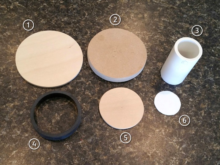
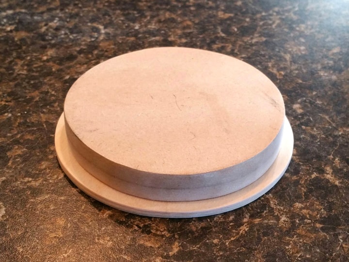
After prepping my parts, this is what I made, all with leftover material from previous steps!

  1. 3-1/2" diameter x 1/8" thick disc, from leftover Baltic birch plywood (from V-hook build).

  2. 3-1/4" diameter x 1/2" thick disc, from 2 glued layers of 1/4" MDF (from motherboard).

  3. 2-3/8" length of 1" inside diameter PVC (1-5/16" outside diameter).

  4. 1/2" length of 2" inside diameter ABS pipe (2-3/8" outside diameter) (from booster build).

  5. 2-1/4" diameter x 1/8" thick disc, from leftover Baltic birch plywood (from V-hook build).

  6. Scissor-cut oversize disc of leftover sign plastic, for capping the bottom of the vacuum tube.

Before assembling anything, I gave the edges of the wood discs a thin coat of white glue. This helps seal the edges and enable paint to adhere better. I gave the glued edges a light sanding afterward.

For the larger stepped disc, I superglued the MDF disc onto the larger plywood disc.

For the vacuum tube base, I superglued the smaller plywood piece onto the ring of ABS pipe, and capped the PVC tube with sign plastic, using my previously-mentioned glue-and-sand process.

To mount the vacuum tube on the disc, I first found and marked on the disc the center and edges where the pipe will go, so that it would be properly centered. I then superglued them together.

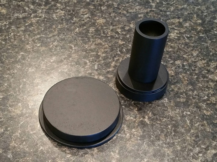
Once the darn humidity levels went down, I finally painted these guys using my usual black spray formula.

Finally, I mounted them on the pack using epoxy and some hot glue in spots in order to hold the pieces on the pack while the epoxy cured.

Done and done. Next post, I’ll show how I scratch made some convincing Clippard valves for three and a half bucks each!

Thanks for reading,

Bill

RUNNING PARTS COST:

– NO MONEY SPENT –

TOTAL: $244.92

Can we get this post pinned? Some tremendous scratch techniques here. I love fabricating. I had to improvise a lot on my recent build so this thread is a joy to follow.

Wow, thanks DarkSpectre for the nice comments. When this thread is done, I’m going to have to contact the admins anyway, because I can no longer edit the first post, and I was working on an ongoing table of contents so that people could zero in on any particular component.

So if enough of you guys think this should be pinned, I can ask for that as well. :slight_smile:

Very kind words, it keeps me going. Thank you! :slight_smile:

Bill

My pleasure, sir. Builds like this with can be useful tools for those who want a pack but feel they don;t have the skills. I didn’t know anything about builds when i started summer of 05 but you can surprise yourself.

One thing i did stumble onto is that Wilton makes 10 inch cake pans that have the correct shape and rounded edges. They cost more but they look the part. I used a 9 inch pan with my wife’s pack and a 10 for the RGB pack I built

NOW you tell me…

Guess it’ll have to wait for V2. :slight_smile:

Of course, there’s always…

image

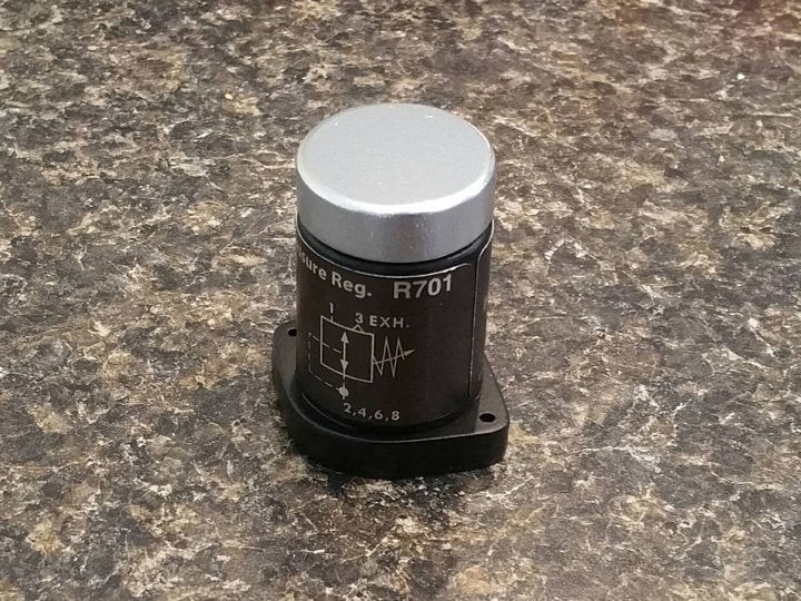
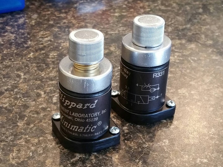
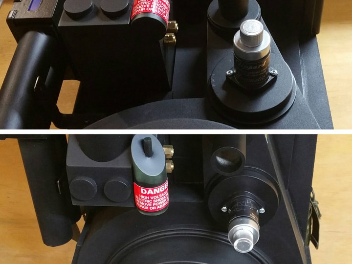
27. CLIPPARD VALVES

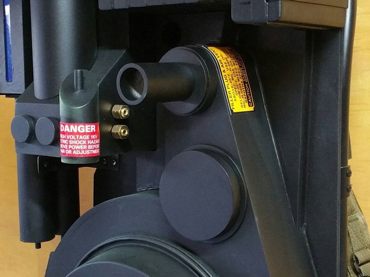
The “Clippard” valves can be found on the large stepped disc on the synchronous generator, and on the proton gun. Although they can be found online these days, I found them to be too cost prohibitive for my build, especially since it was pretty straightforward building some convincing copies.

I’ve seen people online use White-out bottles and 5-hour Energy bottles, but none of them seemed close enough to the real thing.

Note: I will be documenting below the steps I employed to build a single Clippard valve. Everything has to be doubled/duplicated for the second one! :slight_smile:

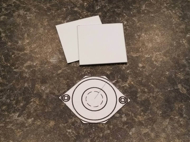
To start, I printed Stefan’s plans to actual size, and cut out the base shape. As I measured, I realized the base shape can be easily approximated by cutting the corners off a perfect square. So I cut two squares of leftover sign plastic to match.

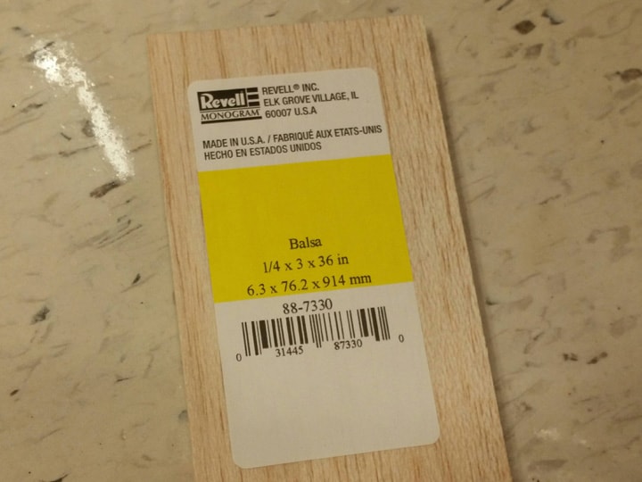
Next, I picked up a ridiculously overpriced piece of 1/4" thick balsa wood at Michaels:

A 3/8" thick piece would have been a little more accurate, but this works for me.

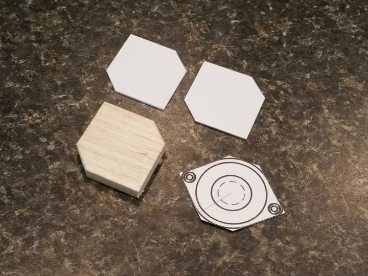
The idea here is to build a “sandwich” of sign plastic around the balsa, giving the whole base more stability and paintability. So I cut the corners off the plastic pieces, and cut a balsa piece to similar dimensions as well.

I then glued the “sandwich” together using superglue. It’s important to avoid epoxy, white glue, or silicone-based adhesives here, because they don’t sand very well.

Next, I sanded the base piece to shape using 220-grit sandpaper and a sanding block, rounding everything according to the plans, taking care to do it slowly. I cleaned it up with 400-grit.

After this, I coated the top (and especially sides) with two coats of white glue. This seals the balsa and helps it keep from chipping or splitting.

Also, I located and drilled two small pilot holes for the screws. It is important to do this carefully, and only after the white glue application, because the balsa wants to chip off.

The base is complete. For the body, I simply capped 1" inside diameter PVC pipe, with sign plastic as my “caps” (as I’ve shown previously). It is all sanded smooth and all edges but the bottom have been rounded quite a bit.

Notice that this is done in two pieces. I did this in order to make the body more realistic. The rounded edges coming into contact makes for a very pronounced seam, much more convincing than simply masking off during painting. It’s a little more work, but REALLY adds to the look of the finished product.

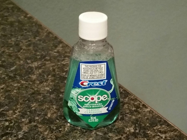
For the lids, I picked up two travel-size bottles of Scope mouthwash at my local dollar store:

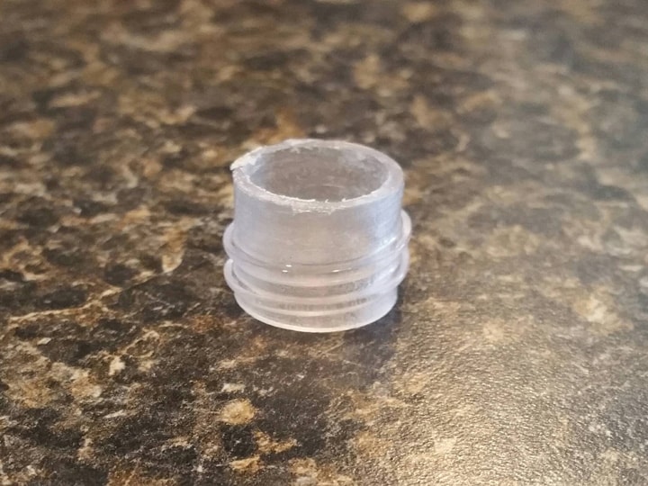
I not only used the lids, but it turned out to be very important to save the threaded tips of the bottles as well. I cut them off with a hacksaw, lightly sanded them, and turned them upside-down. It was also necessary to sand out the insides just enough so that a 1/2" dowel would fit inside.

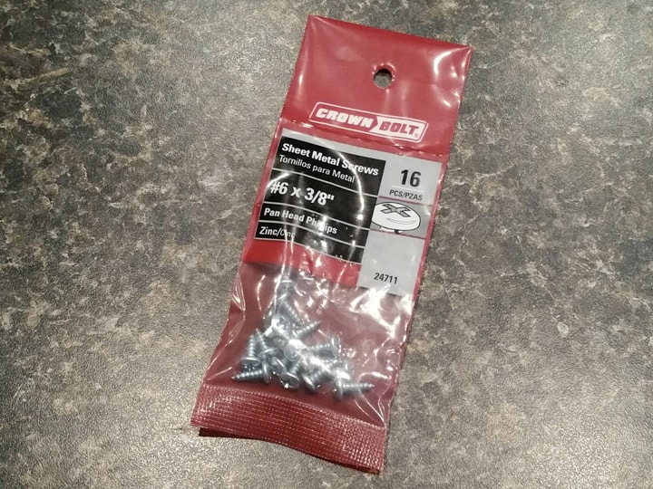
For the base screws, I picked up a pack of these #6 x 3/8" sheet metal screws. They are cosmetic only, as anything longer or larger will risk busting the balsa.

EDIT: I ended up not using these screws, but went with longer 3/4" screws instead. They are no longer cosmetic, but instrumental in securing the valve to the wood disc underneath.

After that, I painted everything: base and lower body with black spray, upper body and lid with silver spray, and threaded piece with brass model paint.

I also cut a piece of 1/2" dowel (left over from the crank knob) to the exact inside height of the mouthwash cap.

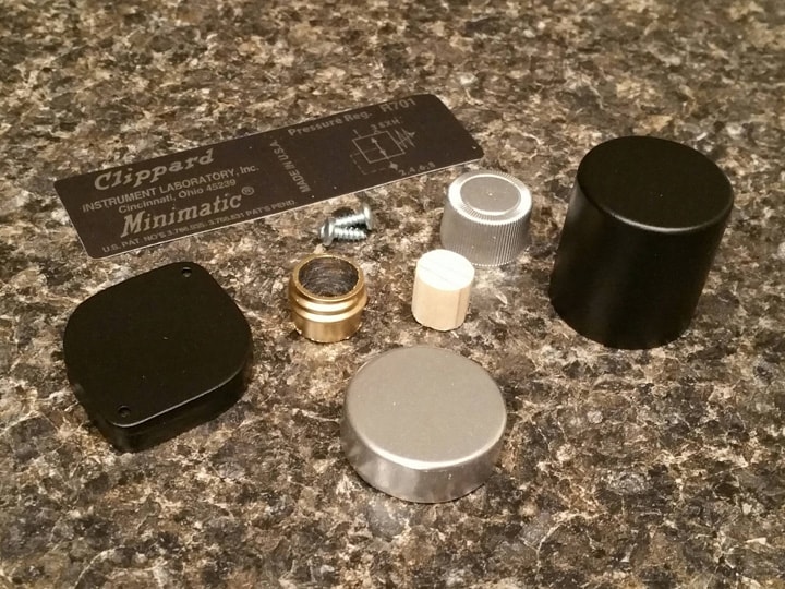
My pieces were ready for assembly:

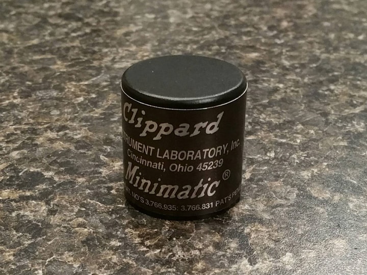
My first assembly step was to apply the metallic label on the PVC body. It’s quite difficult to add it later. It was also necessary for me to cut about 1/8" off the end of the label in order to get it to fit properly, as it was too long for my PVC pipe.

Note: The two Clippard labels are different. The one marked “R701” goes on the gun, and the one marked “R331” goes on the proton pack.

I then glued on the upper body and base using a small dab of epoxy. I was especially careful to make sure the lower body is correctly oriented on the base, so that the label is facing the right direction.

Then, I glued the dowel inside the threaded piece, with the dowel length sticking up past the non-threaded end of the bottle tip.

I flipped this whole thing upside down and glued it into the cap, ensuring that the threads will show.

Note: Most pack builds seem to show brass threads for the gun’s Clippard valve only. The one on the pack looks fully screwed in. As a result, I only used the threaded tip for one of the valves.

After gluing this onto the top of the valve body, and adding the mounting screws, my Clippard is done!

EDIT: Because I ended up using longer screws, they went in last.

Rinse and repeat (this time without the threaded tip), and my second one for the pack is ready.

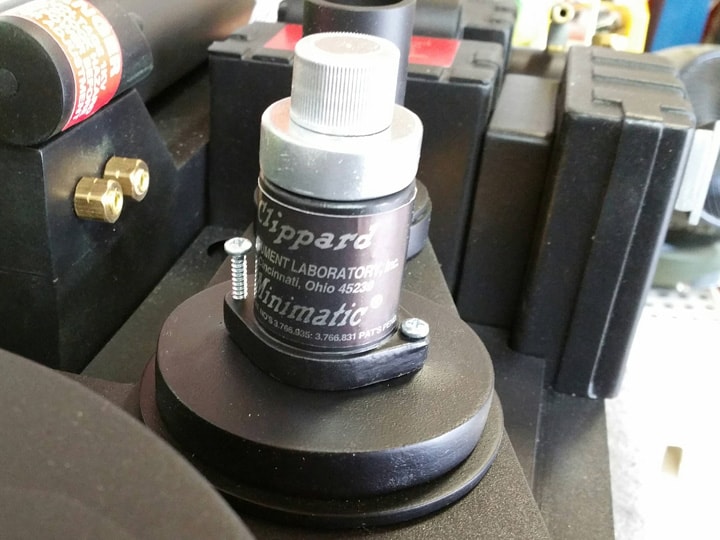
And finally, I glued my R331 Clippard onto the pack, using my usual epoxy and hot glue combination, saving the R701 valve for later.

UPDATE: After a helpful post below from Alan Hawkins, I decided to secure the Clippard using the screws. So I took out the 3/8" long #6 screws, and replaced them with 3/4" versions instead. It was necessary to remove the valve carefully, clean up the surface, drill pilot holes into the stepped disc, and epoxy the valve back in. Then, I was able to put the longer screws in. Much more secure!

And that’s it. Next post, it’s time to tackle that ion arm.

Thanks for reading!

Bill

RUNNING PARTS COST:

$4.19 - 1/4" thick x 3" x 36" balsa wood (Michaels)

$1.00 - Travel-size bottle of Scope mouthwash (dollar store)

$1.00 - Travel-size bottle of Scope mouthwash (dollar store)

$0.98 - #6 x 3/4" round head sheet metal screws (16-pack) (Home Depot)

$244.92 - previous total

$7.17 - this stuff

TOTAL: $252.09

Those clippards are incredible!

Those look great! Question, Is there a way to bolt it from behind? I’m worried it might get knocked off.