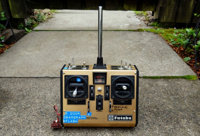
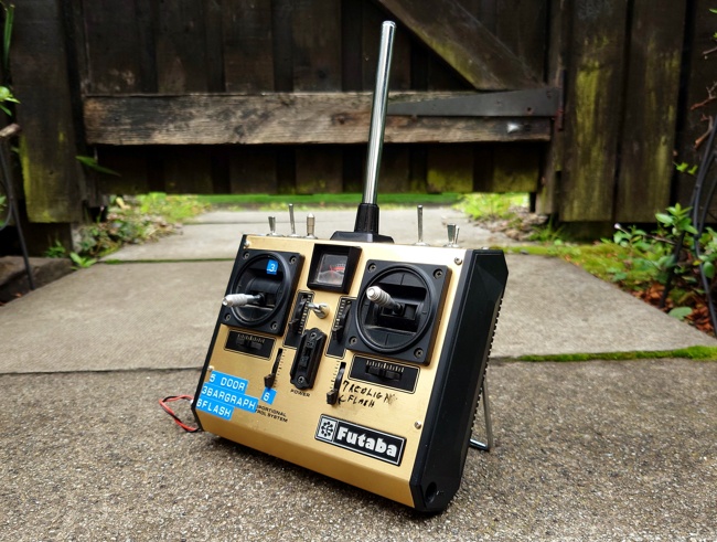
That’s awesome. Such an inspiring build, can’t wait to see full RC functionality. Nice job
Thanks for the kind words, Ecto7 
I’m so close to being able to get this old thing fired up again.
Just a part or two to go.
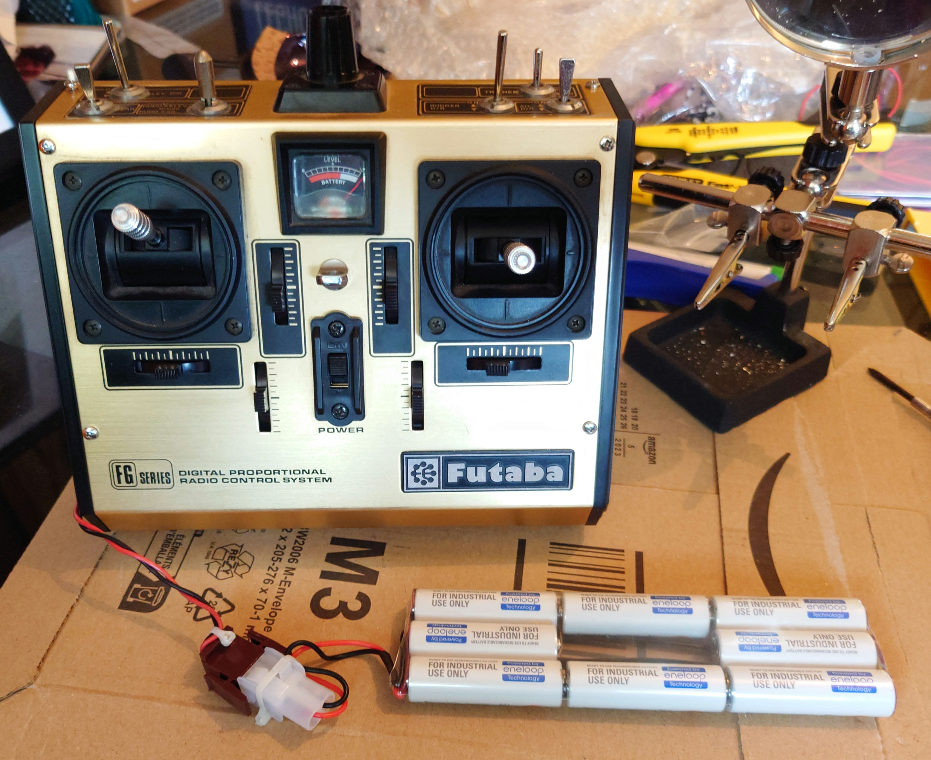
I recently sourced some replacement batteries and today I took delivery of a couple of custom boards.
One controls a randomised array of six high intensity strobes, for use as the trap cartridge lighting setup.
The other is a small sound board and speaker.
Although I’m unsure if I’m actually going to implement this one.
Both are designed to work with a Futaba receiver setup.
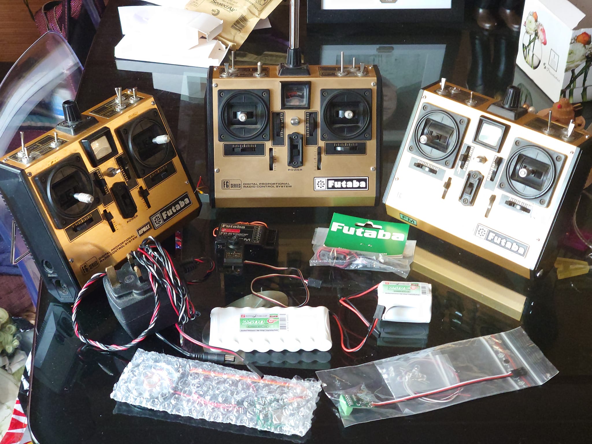
Funny seeing that picture because when I got a decent priced ebay auction, it was for 3 transmitters.. So I do have two extra ones, lol
Haha well at least we have plenty of spare parts.
I had just imported the correct one from the US when a friend had mentioned that his dad was an avid RC hobbyist back in the day and asked if I needed anything.
I was looking for a 35mhz module and a battery charger but he showed up with that plus two extra receivers and these other two transmitters.
They’re the UK versions with some additional Ripmax branding and lack the DS TX duplex safety switch on the top left, but they’re otherwise identical.
I might end up accuratising them once I have the imported one up and running.
So dealing with electronics, never mind vintage electronics is all very new to me and its been a bit of a steep learning curve.
I’ve had untold frustration lately trying to get the old Futaba up and running.
I bought multiple 9.6v Nihm batteries, various chargers and new fuses but it just would not seem to work.
I tore the thing down, checking for bad connections, etc but everything seemed fine.
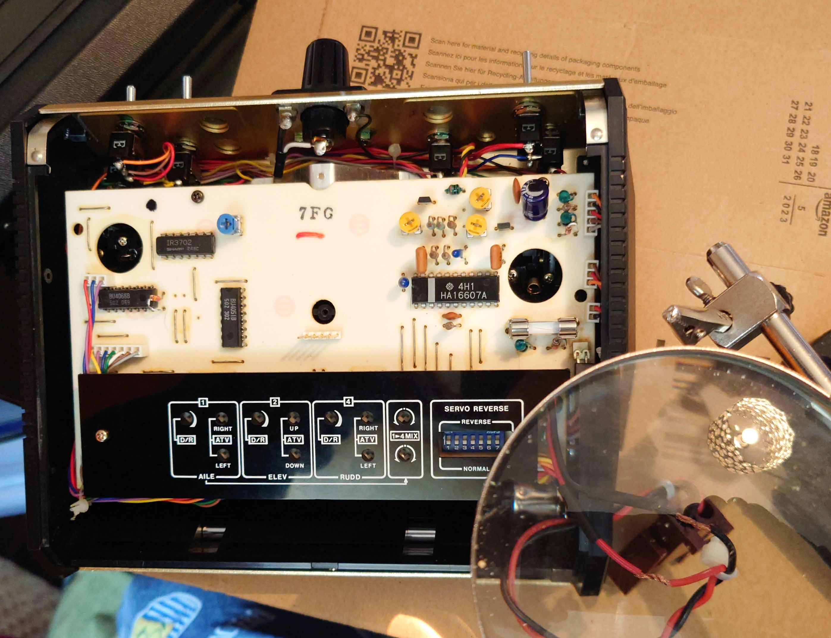
Well, tonight during another teardown I noticed once I’d pulled it out that the frequency module had a socket on the side.
On a whim I plugged one of the receiver crystals into the socket, flipped the switch and..
It’s Alive!
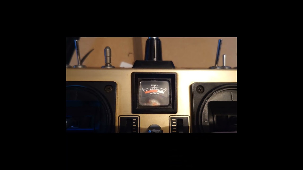
After all that it turned out to be one tiny component, which was stopping the circuit from completing.
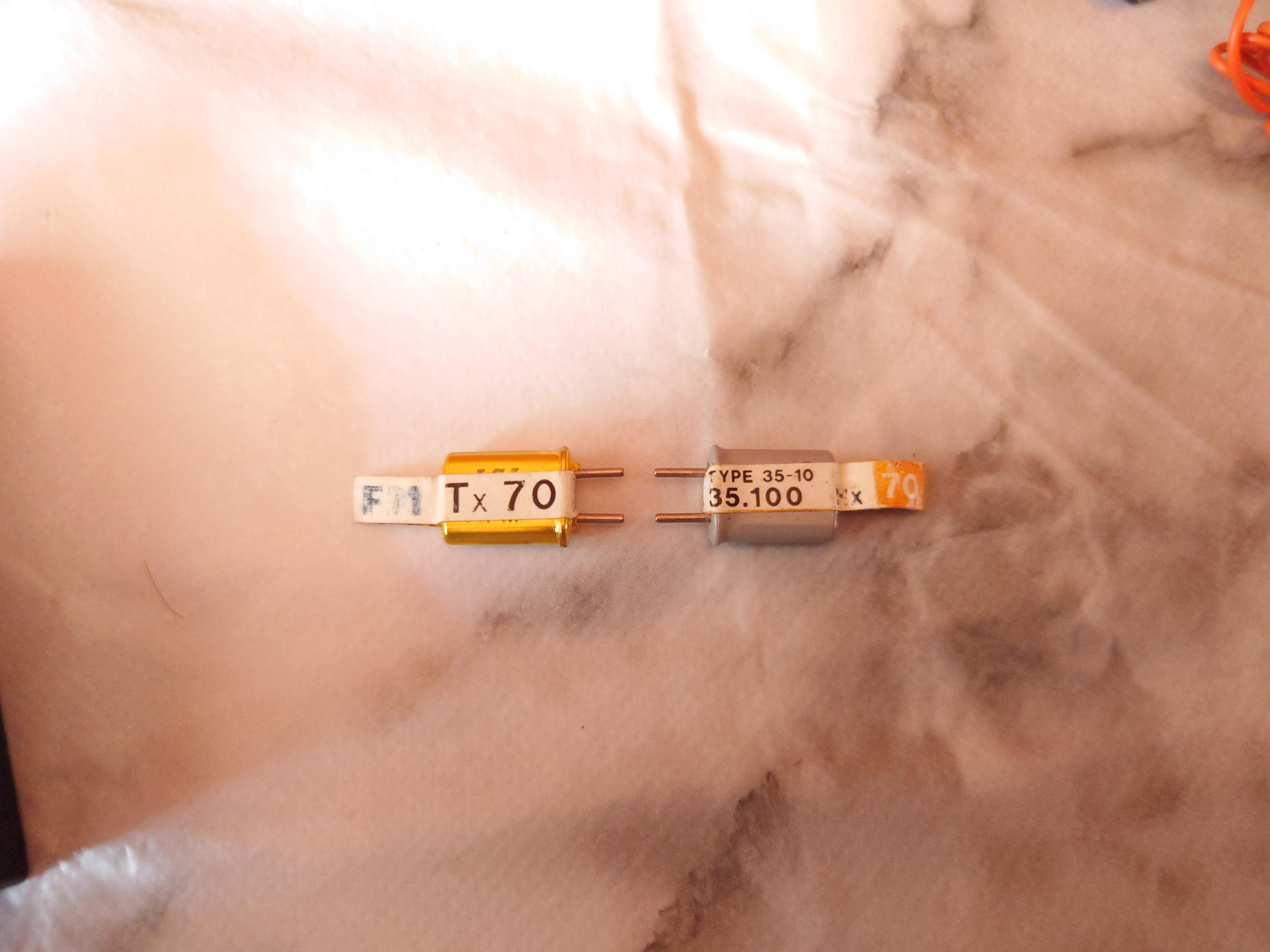
Now I just have to wait for some matching channel and frequency transmitter and receiver crystals to arrive and hopefully everything will communicate.
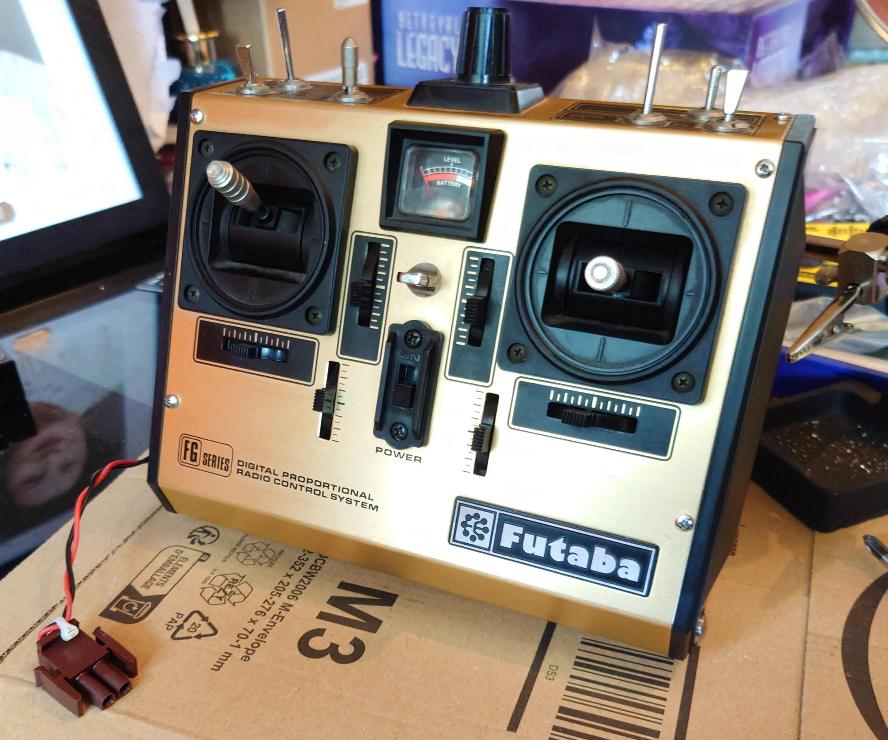
Now that I have the transmitter to the point where it’s powering up, I went ahead and changed out the battery connectors for Mate N Lok connections.
Thanks to master Ghost trap smith, Cole Funseth for the info on those.
A male connector for the transmitter, routed through the side panel near the original charging port where its soldered to a Futaba J connector and a female connector for the battery, with the small size Panduit dome top barb Ty’s used as a strain relief.
This will allow me to use external battery packs as per the production used setup.
I may even make a faux Makita battery casing or gut an original one in order to house a Nimh battery, as they reportedly used Makita batteries as an external power source on the original transmitter.
I still need to add some Dymo labels and sharpie marks but it’s almost there.
The crystal’s that I’d ordered arrived today, so with that I was able to get the Transmitter to communicate with the receiver and test out the various channels using a couple of servos.
Thankfully, everything is functioning perfectly.
The servo for the doors on the RC trap was actuated via the landing gear switch (top left most switch towards the front) as you can see in this short clip.
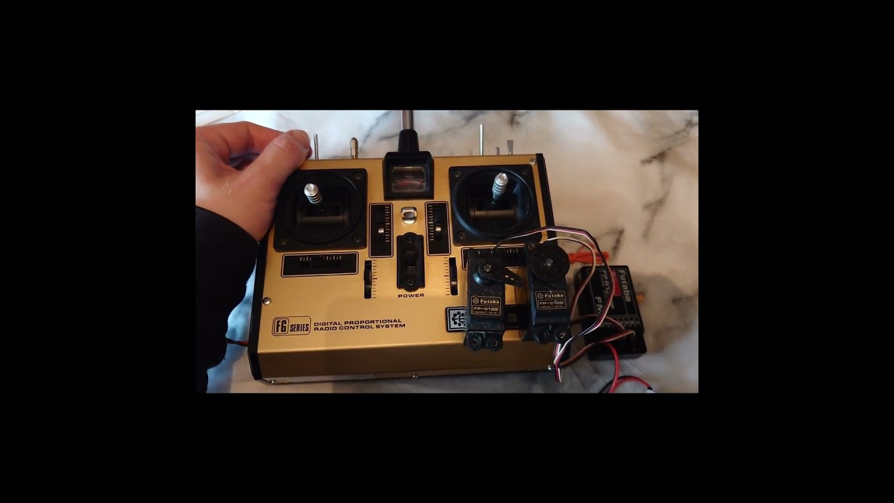
Now that I have everything at the stage where its all functional and communicating, I’ll wire up the strobes and test that part of the lighting setup.
After that, I’ll be able to wrap this part of the project up for now and move back into the physical build again, soon until such time as its time to start dry fitting electronics and figuring out the bargraph implementation.
For anyone interested in tackling this control setup for a trap, you’ll need the following:
1: A Futaba FP-7FG/K Transmitter, specifically the model with the locking 3 way bullet style switch, although these can be purchased separately and soldered in.
2: A Futaba FM Frequency module for the transmitter (I went with 35mhz frequency).
3: An eight channel Futaba receiver of the same frequency as the module.
4: A matching pair of Transmitter and Receiver crystals, for example I’m using a set of 35mhz crystals which are both set to channel 70.
5: A Futaba receiver power switch and charging harness.
6: A 9.6v NiMH transmitter battery.
7: A 6v NiMH receiver battery with male futaba connector.
8: A smart charger rated to charge both NiMH batteries.
You can use a standard futaba charger for these but it’ll take 30 hours or more depending on the MAH rating to charge each battery vs 2.5 hrs with a smart charger.
9: 2X male Mate N Lok connectors and pins, one wired to a male futaba J connector, attached to the transmitters internal battery connection to allow for external battery use, the other attached to the charger.
10: 2X female Mate N Lok connectors and pins, One to attach to the 9.6v battery, the other to wire to a female futaba J connector for use as a charging adapter for the 6v receiver battery.
11: 4X small Panduit dome top barb ty’s for use as strain reliefs on the Mate n Lok connectors
For the lighting and door mech you’ll need:
1: A Futaba servo, servo arms, X shaped servo horn and servo ball linkages.
2: A Futaba receiver compatible lighting array for the cartridge.
3: A blinking LED for the Linrose pilot lamp, wired to a futaba compatible pico switch.
4: A 28 segment bargraph and 5mm amber LED assembly, controllable via a male futaba J connector (I’m still working that one out, myself)
Another step closer to a suite of electronics for the trap.
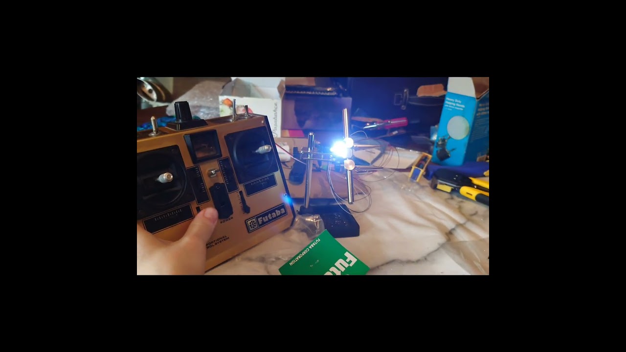
Today I assembled and tested the strobe array for use as the cartridge lights.
Controlled via the 6th channels slider on the transmitter.
Another small update.
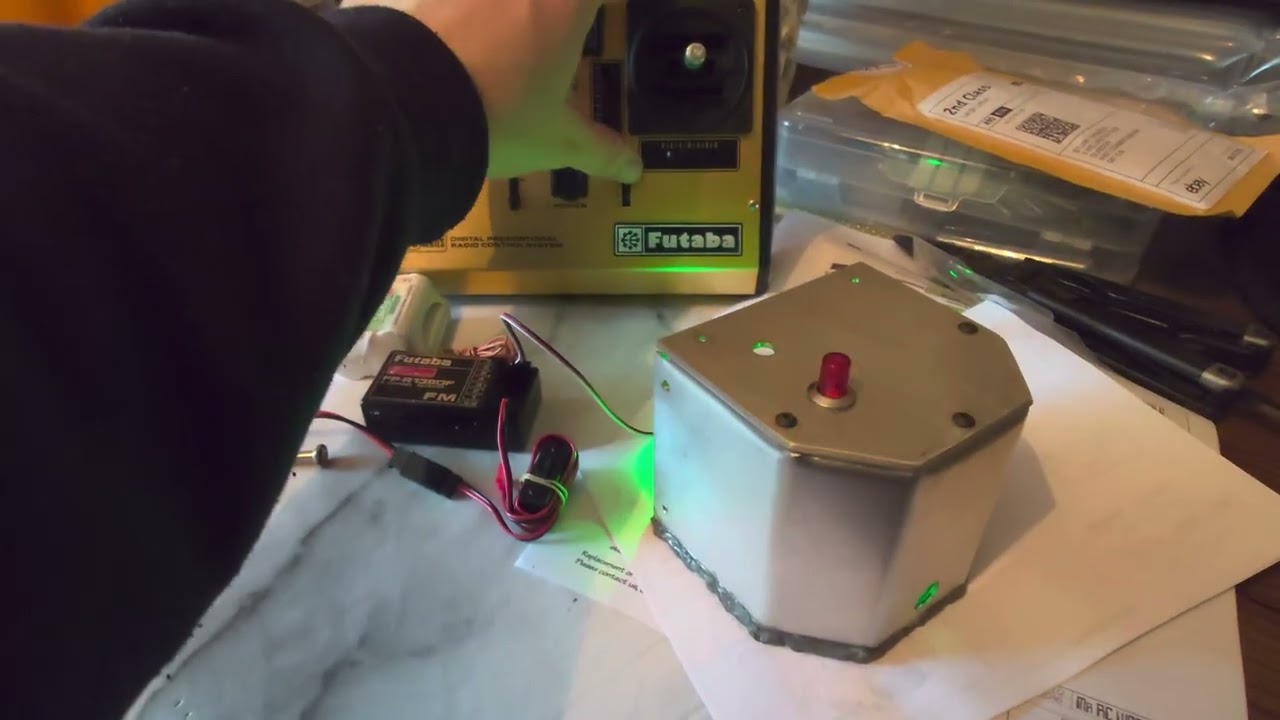
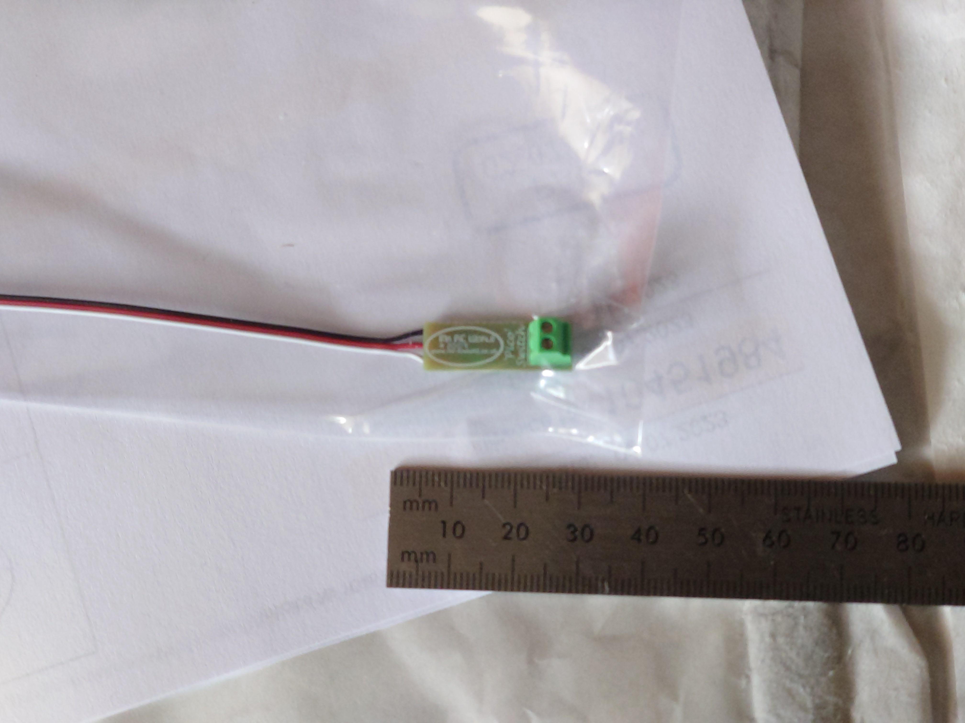
I have the Linrose pilot light up and running thanks to this small Pico switch, which converts the PWM signal from the receiver, allowing the 7th transmitter channel to switch a flashing led on.
The green light is a power indicator on the Pico switch.
I may cover it with some heatshrink to eliminate the green glow once it’s installed.
This has taken untold hours of R&D, head scratching, swearing and a little crying but I’ve finally got a Futaba controlled 28 segment bargraph and single led setup for my current build.
I’ll most likely add a red gel behind the bezel once I have it to shift the color to orange.
With this, I have the full electronic setup that I need, pending a little soldering so it’s back to the trap build itself.
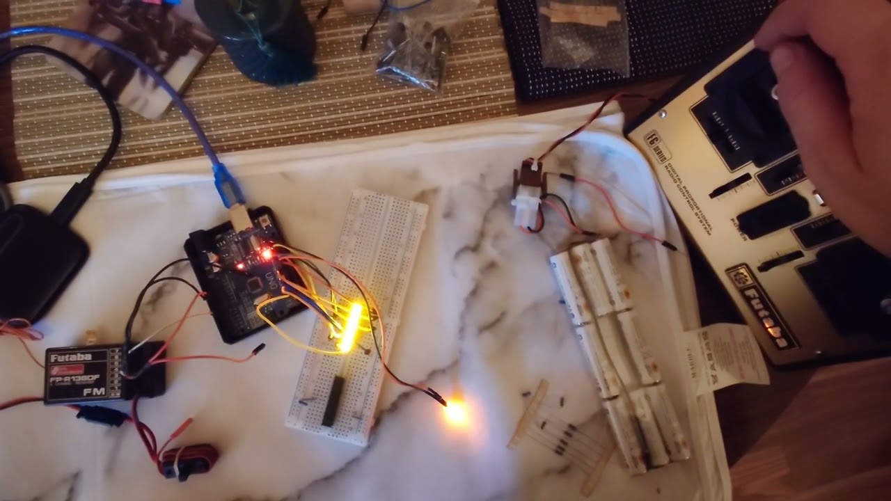
As a quick aside, If anyone is interested in using this control method for their trap build in future ( although I don’t expect many will be) I’d be happy to make the wiring schematic and arduino sketch available.
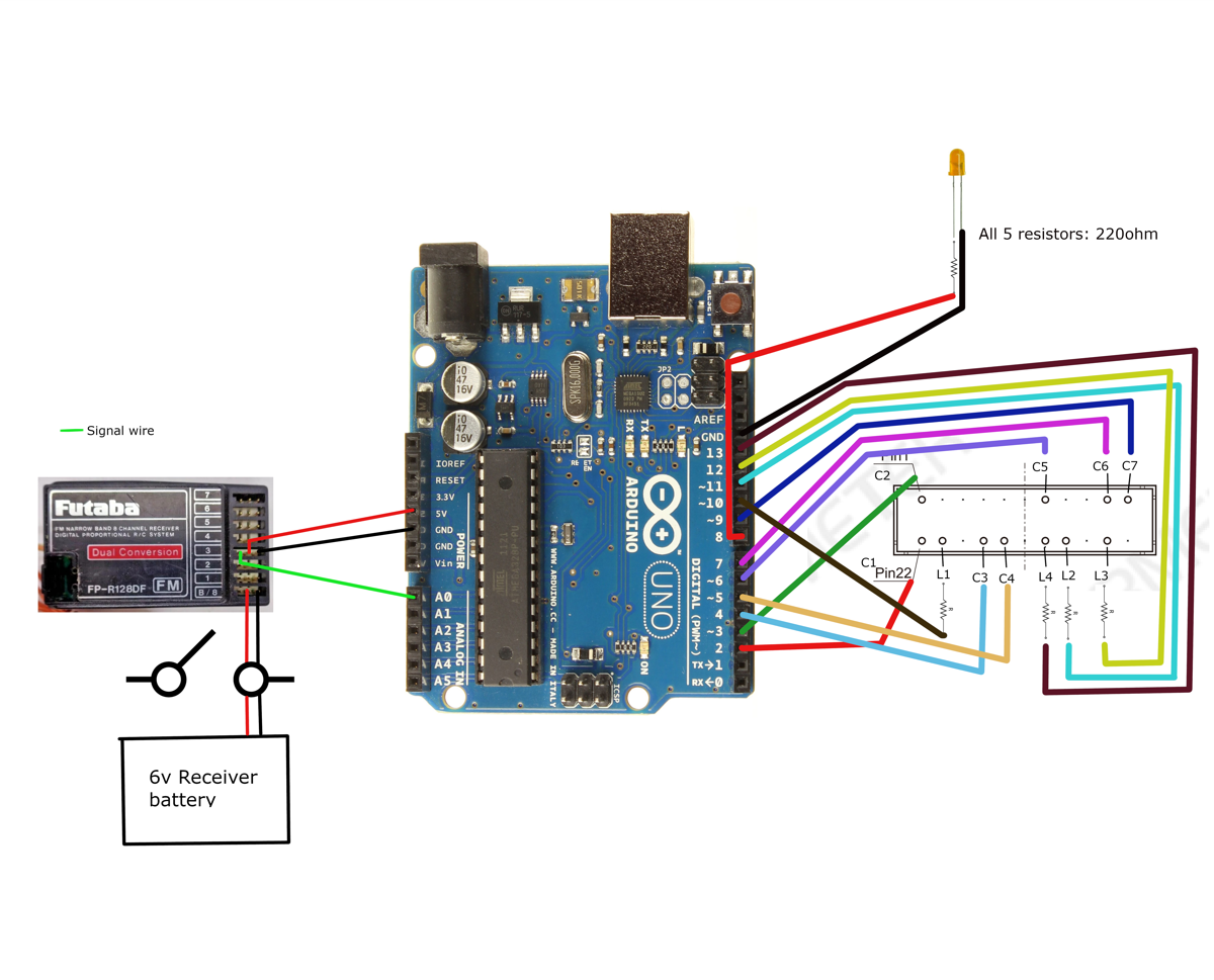
This is written specifically for use with an 11 pin, 28 segment bar graph made by Barmeter.
Firstly, here’s a quick wiring schematic:
And the code:
const int C1 = 2;
const int C2 = 3;
const int C3 = 4;
const int C4 = 5;
const int C5 = 6;
const int C6 = 7;
const int C7 = 9;

const int L1 = 10;
const int L2 = 11;
const int L3 = 12;
const int L4 = 13;

const int cathodePins[] = {C1, C2, C3, C4, C5, C6, C7};
const int anodePins[] = {L1, L2, L3, L4};

const int numSegments = 28;

// Adjustable brightness (0 to 255)
int brightness = 128; // Adjust this value to set the default brightness

const int indicatorPin = 8; // The additional LED indicator pin
const int thresholdValue = 1922; // Adjust this threshold as needed

void setup() {
  // Wait for a moment to allow the initialization process to complete
  delay(1000);

  for (int i = 0; i < sizeof(cathodePins) / sizeof(cathodePins[0]); i++) {
    pinMode(cathodePins[i], OUTPUT);
  }

  for (int i = 0; i < sizeof(anodePins) / sizeof(anodePins[0]); i++) {
    pinMode(anodePins[i], OUTPUT);
    analogWrite(anodePins[i], 0); // Set PWM brightness to 0 (LED off)
  }

  pinMode(indicatorPin, OUTPUT);
}

void loop() {
  int throttleValue = pulseIn(A0, HIGH, 20000);

  // Map the throttle value to control the number of lit segments (0 to 28)
  int numLitSegments = map(throttleValue, 1230, 4000, 0, numSegments);

  // Turn off all segments
  turnOffAllSegments();

  // Turn on segments based on throttle value with adjustable brightness
  for (int i = 0; i < numLitSegments; i++) {
    int cathodeIndex = i % 7;
    int anodeIndex = i / 7;

    digitalWrite(anodePins[anodeIndex], LOW);
    digitalWrite(cathodePins[cathodeIndex], HIGH);
    analogWrite(anodePins[anodeIndex], brightness);
  }

  // Turn on the indicator LED when the throttle value is greater than or equal to the threshold
  if (throttleValue >= thresholdValue) {
    digitalWrite(indicatorPin, HIGH);
  } else {
    digitalWrite(indicatorPin, LOW);
  }
}

void turnOffAllSegments() {
  for (int i = 0; i < sizeof(cathodePins) / sizeof(cathodePins[0]); i++) {
    digitalWrite(cathodePins[i], LOW);
  }

  for (int i = 0; i < sizeof(anodePins) / sizeof(anodePins[0]); i++) {
    // Set PWM brightness to 0 (LED off)
    analogWrite(anodePins[i], 0);
  }
}
Thanks for sharing this! If it’s of any interest someday, I’ve been using the brilliant HT16K33 board for my bargraphs. It has 16 Anode pins and 8 Cathode pins (so it’s enough for a 28 segment bargraph). The main benefit to this is you only need 4 wires going back to the Arduino (SDA, SCL, +5V, GND) to run it, so it keeps the wiring tidy inside the trap and you run short lengths of wire from the bargraph to the board. It’s also small enough to fit in the empty space beneath the bargraph.
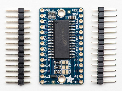
You can also repurpose one of the pins to control the indicator LED next to the bargraph, so that’s effectively 29 LEDs using only 4 wires. I’ve been able to get by without resistors too (my wand bargraph has been going strong for over 2 years now).
First prototype (when I used one for my wand):
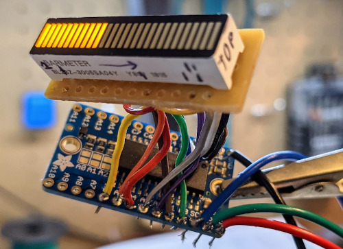
Note that there’s only 4 wires coming out of it back to the Arduino.
The official Adafruit library for it is pretty good, but there’s also some others specifically designed for this bargraph, such as:
- GitHub - cfunseth/BargraphLED: Arduino library to interface with a Barmeter BL28 LED Bargraph Display and an Adafruit HT16K33 Backpack · GitHub (by Cole Funseth)
- ProtonPack/Source/Libraries at master · MikeS11/ProtonPack · GitHub (by Michael Simone)
I bought a pack of these on eBay fairly cheap so I use them in a lot of my projects, including my Tripod Trap builds.
Do you by any chance have a wiring diagram for this method? Kinda hard to see in the picture.
I finished off my Futaba transmitter replica using some dymo labels and marker.
Unfortunately, the marker didn’t take as I’d hoped and smudged as I was moving it, so it’ll need to be redone using something more permanent.
After some trial and error, because these things never turn out to have been done in a straightforward way and I’m just sad like that, I guess.
The labels were made using a vintage 1500 series Dymo embosser which is set up to use 12mm wide tape and has a slightly different font and larger lettering than later models.
They then used 9mm wide tape instead of 12mm, because of course they did :roll: which is why some of the numbers are off centre on the original transmitter, as you have to manually align the tape after each character to stop it from drifting to either side in the 12mm channel on the embosser.