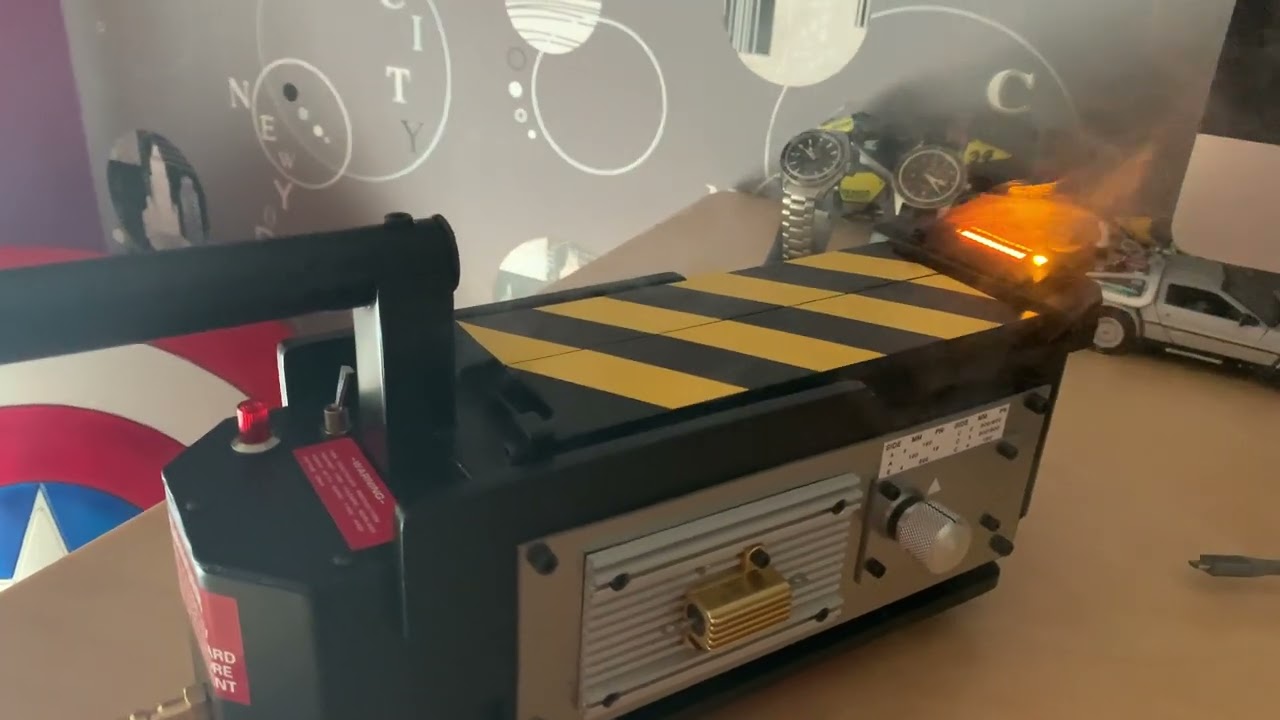
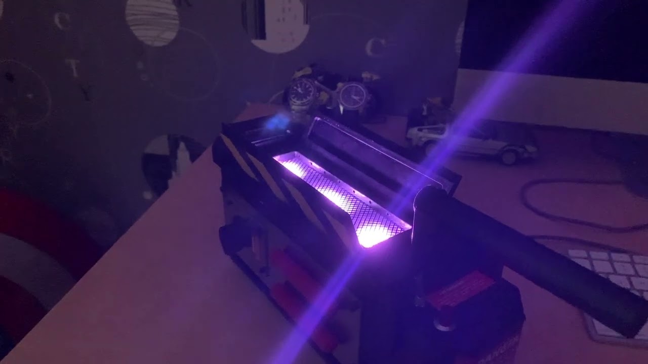
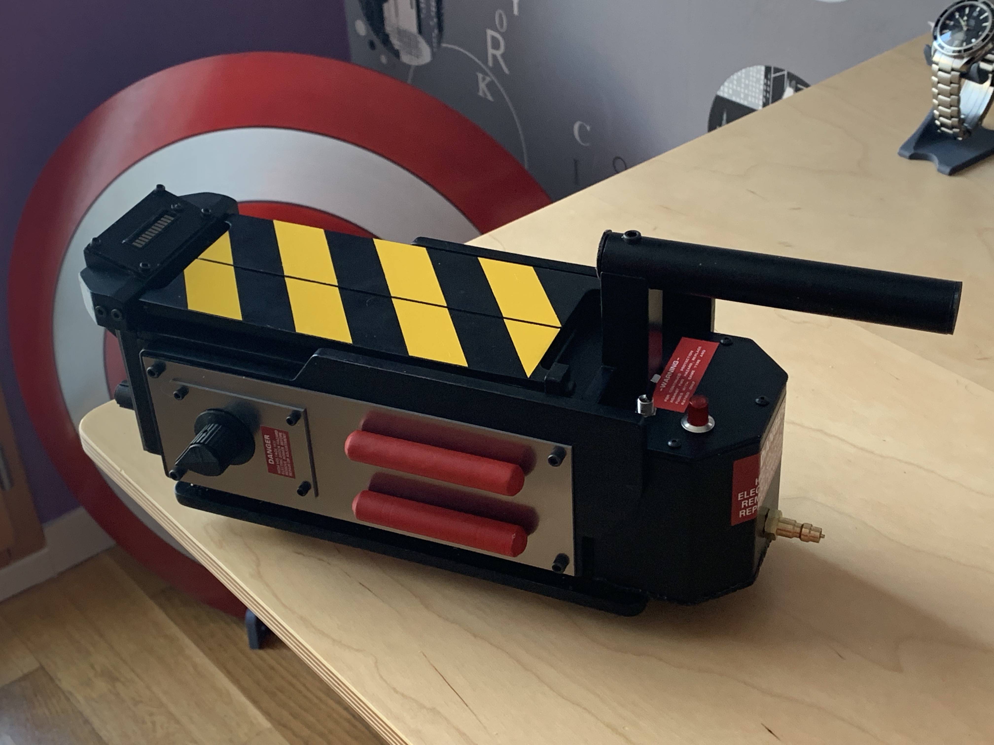
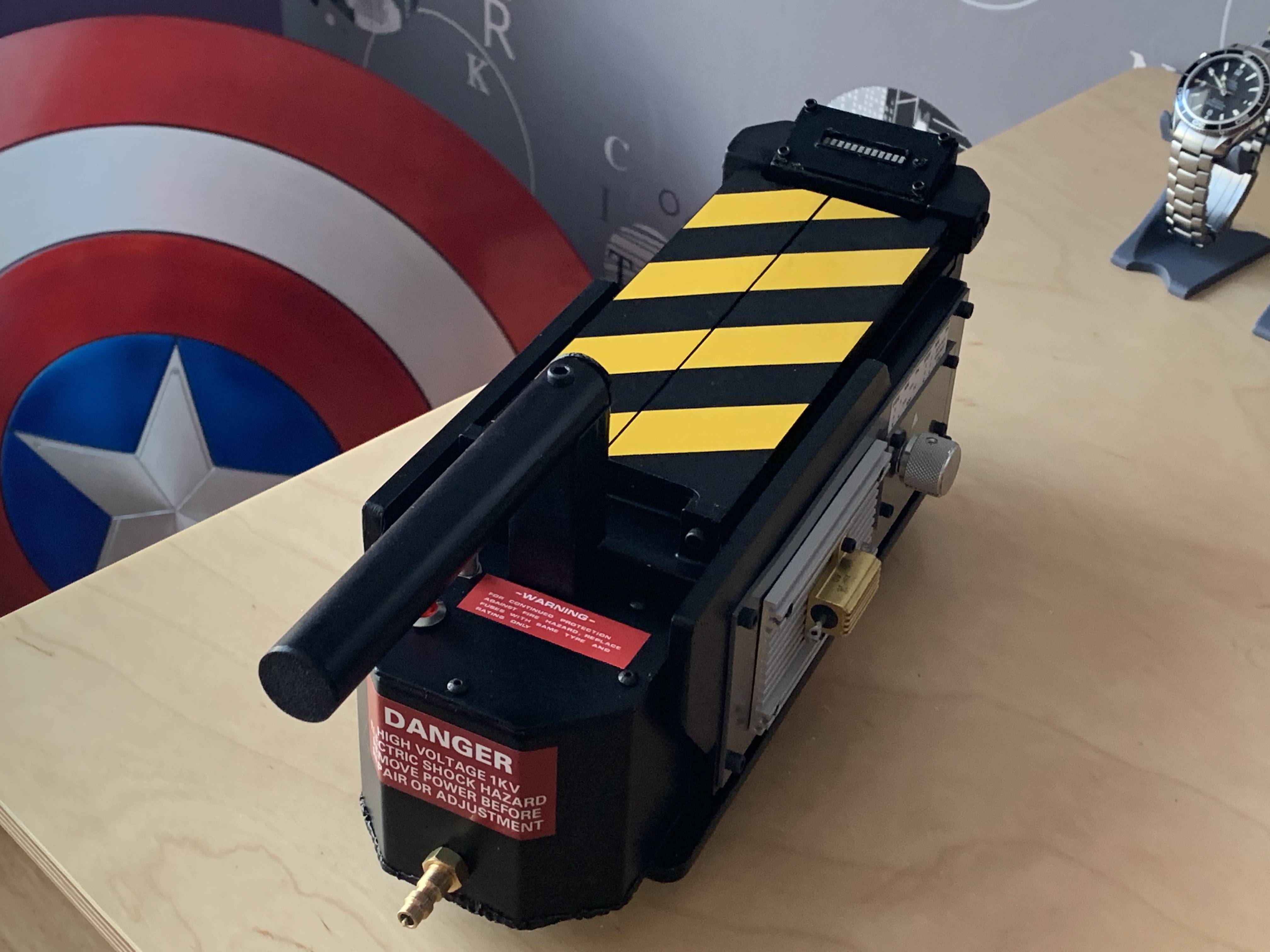
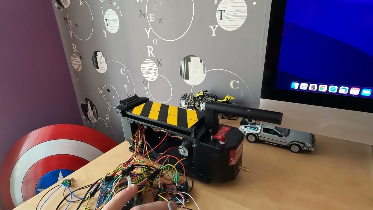
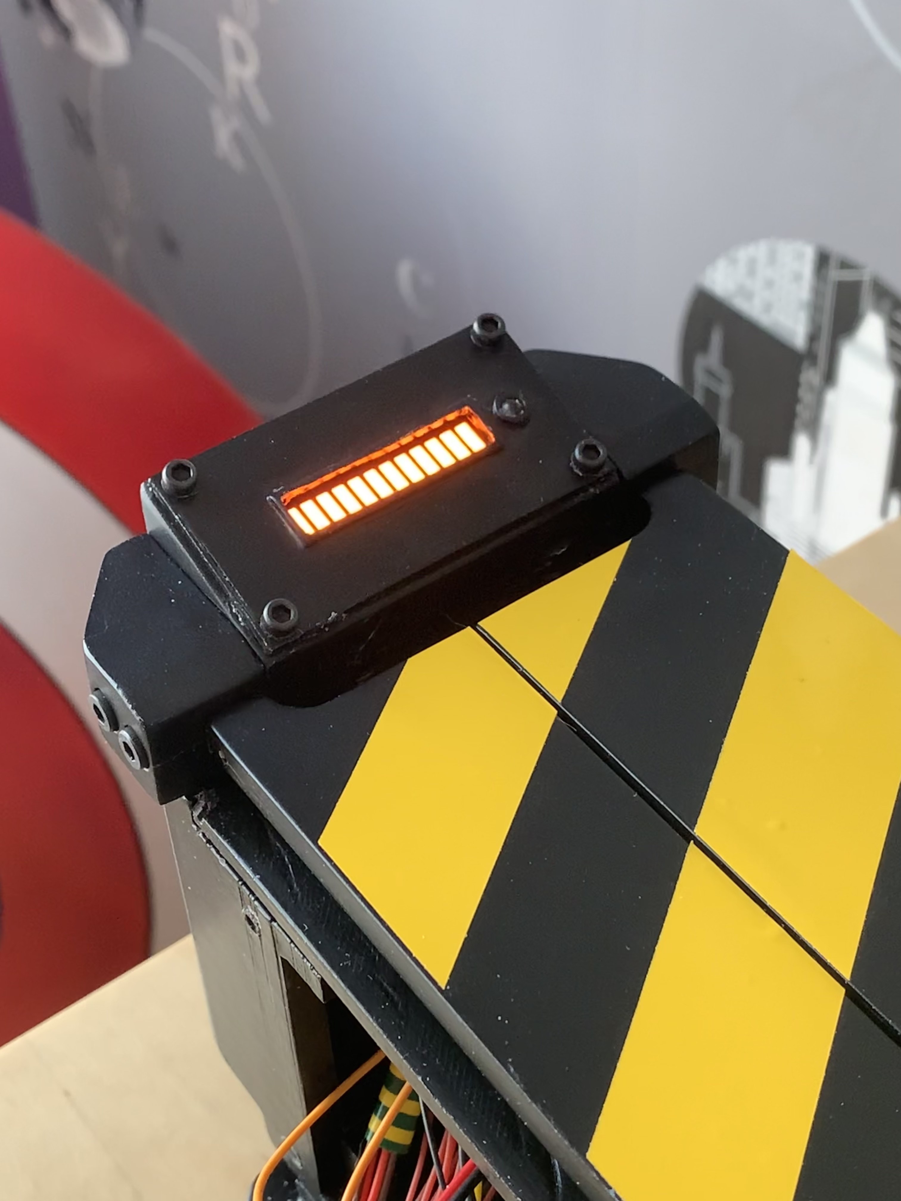
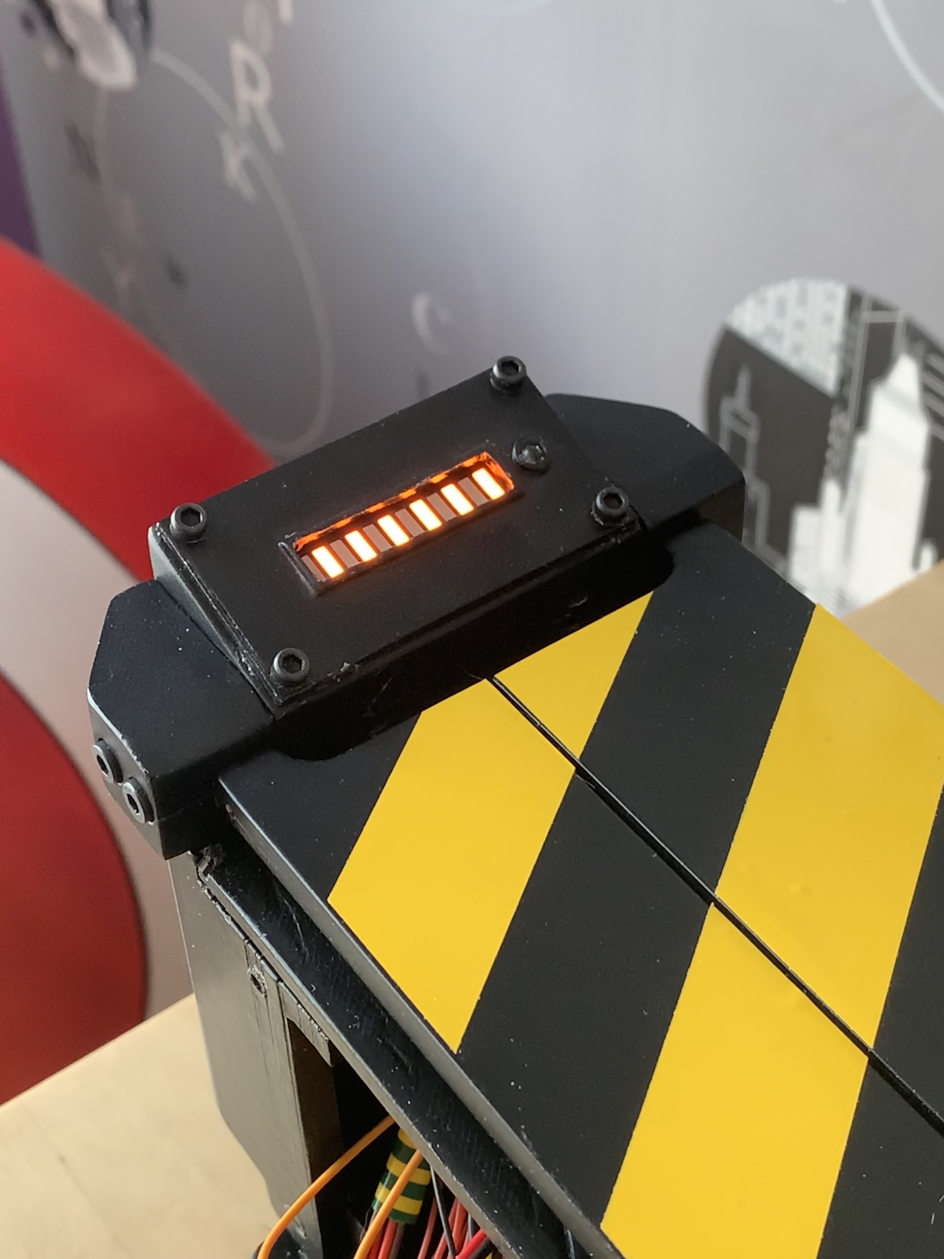
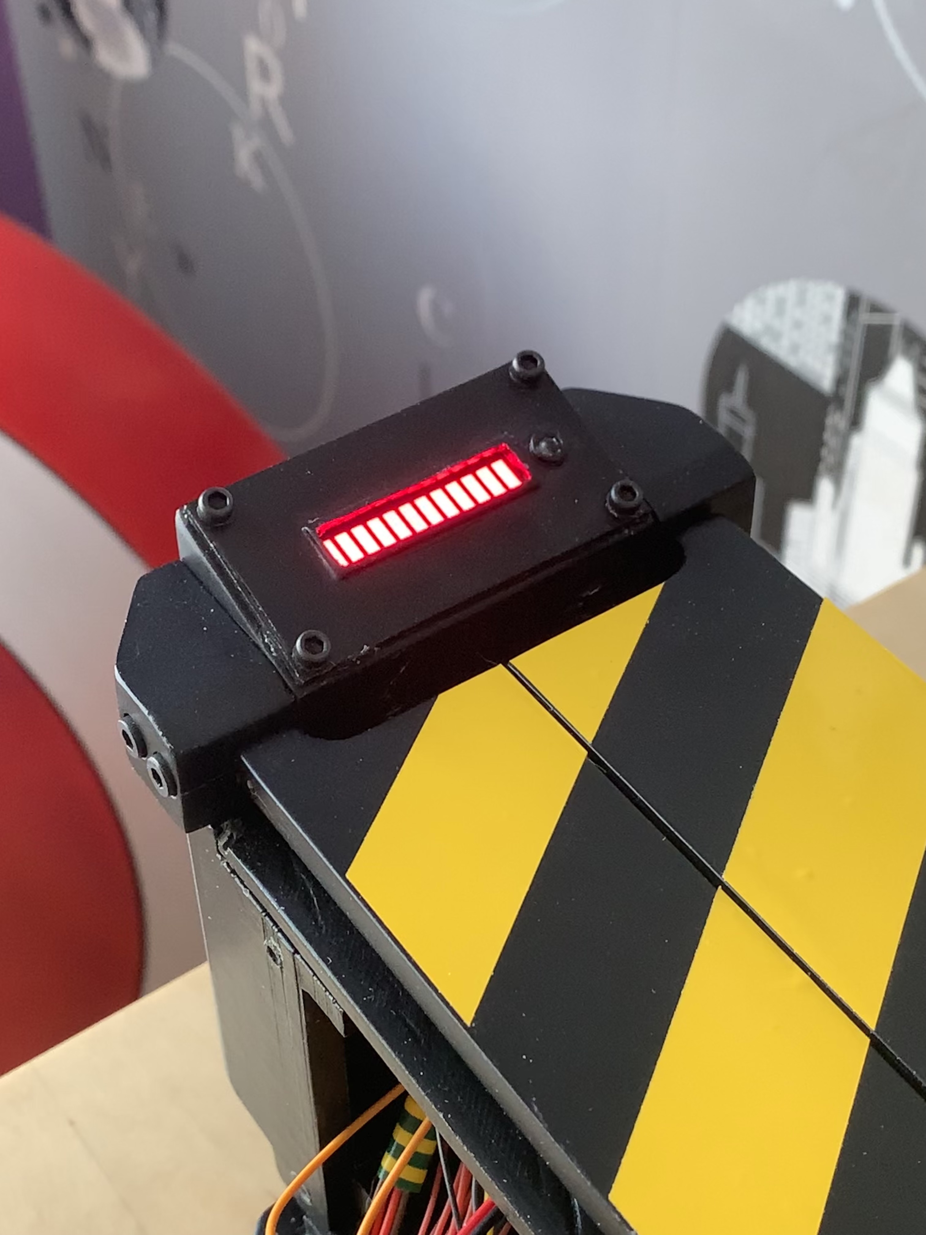
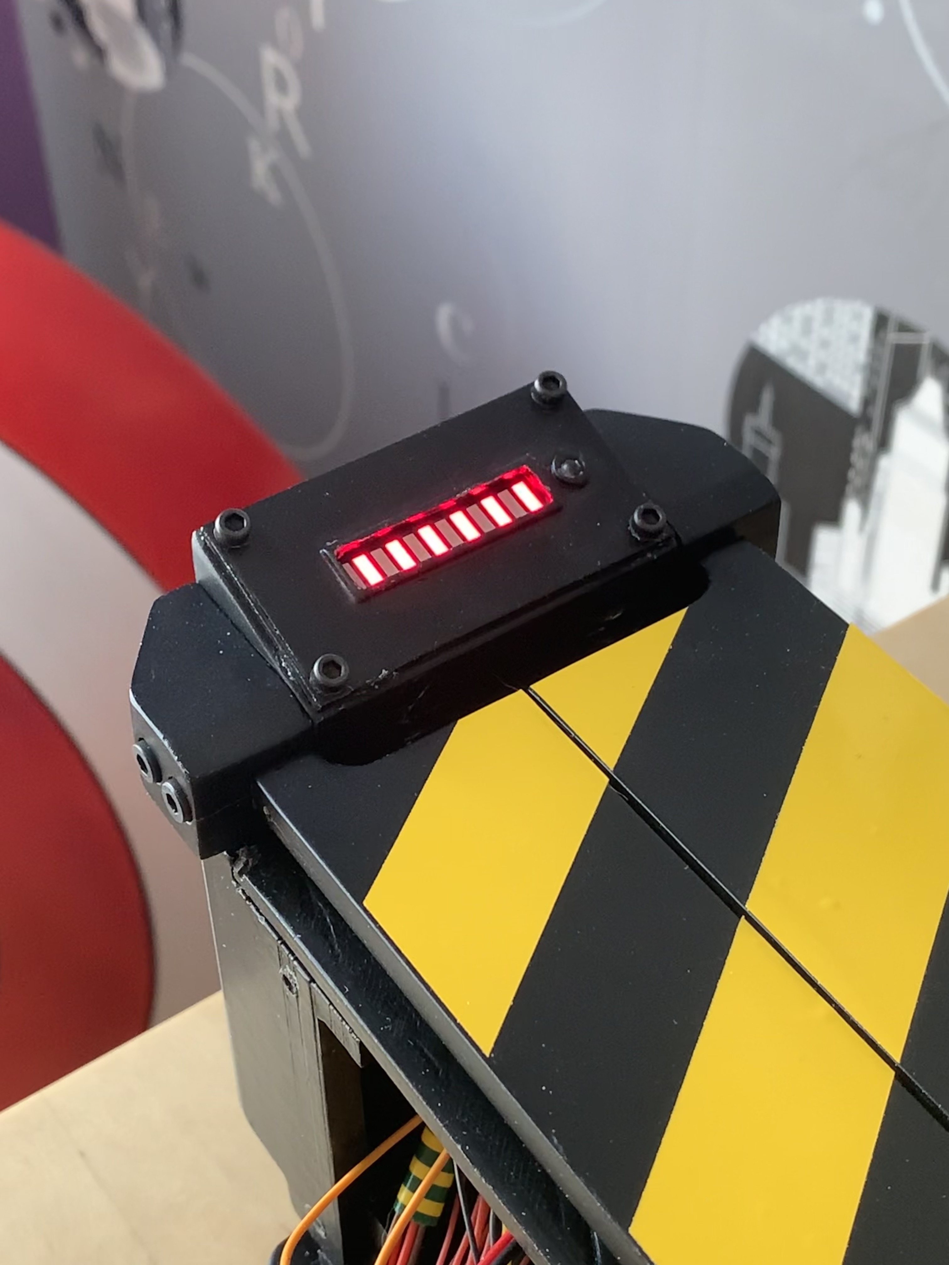
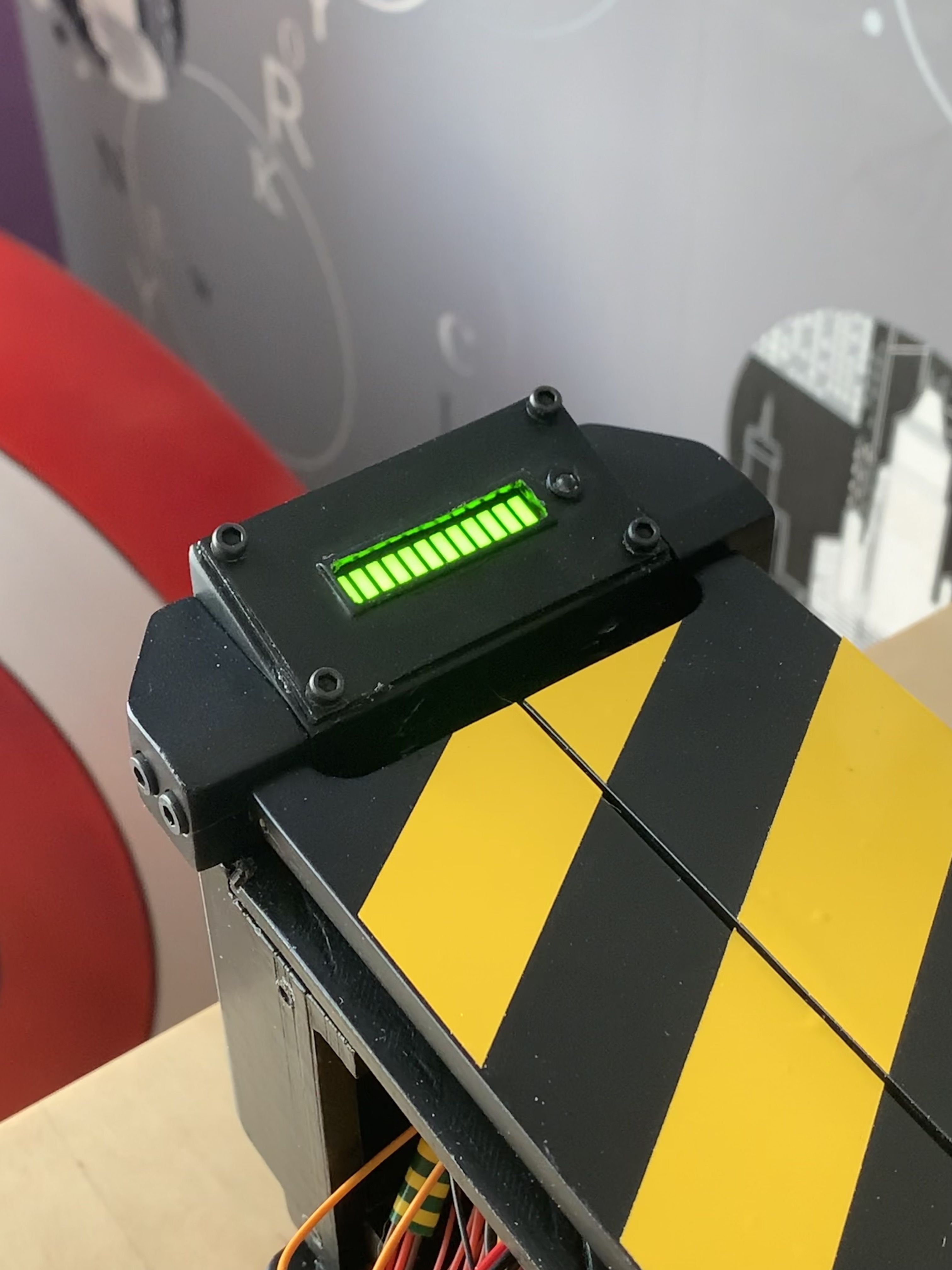
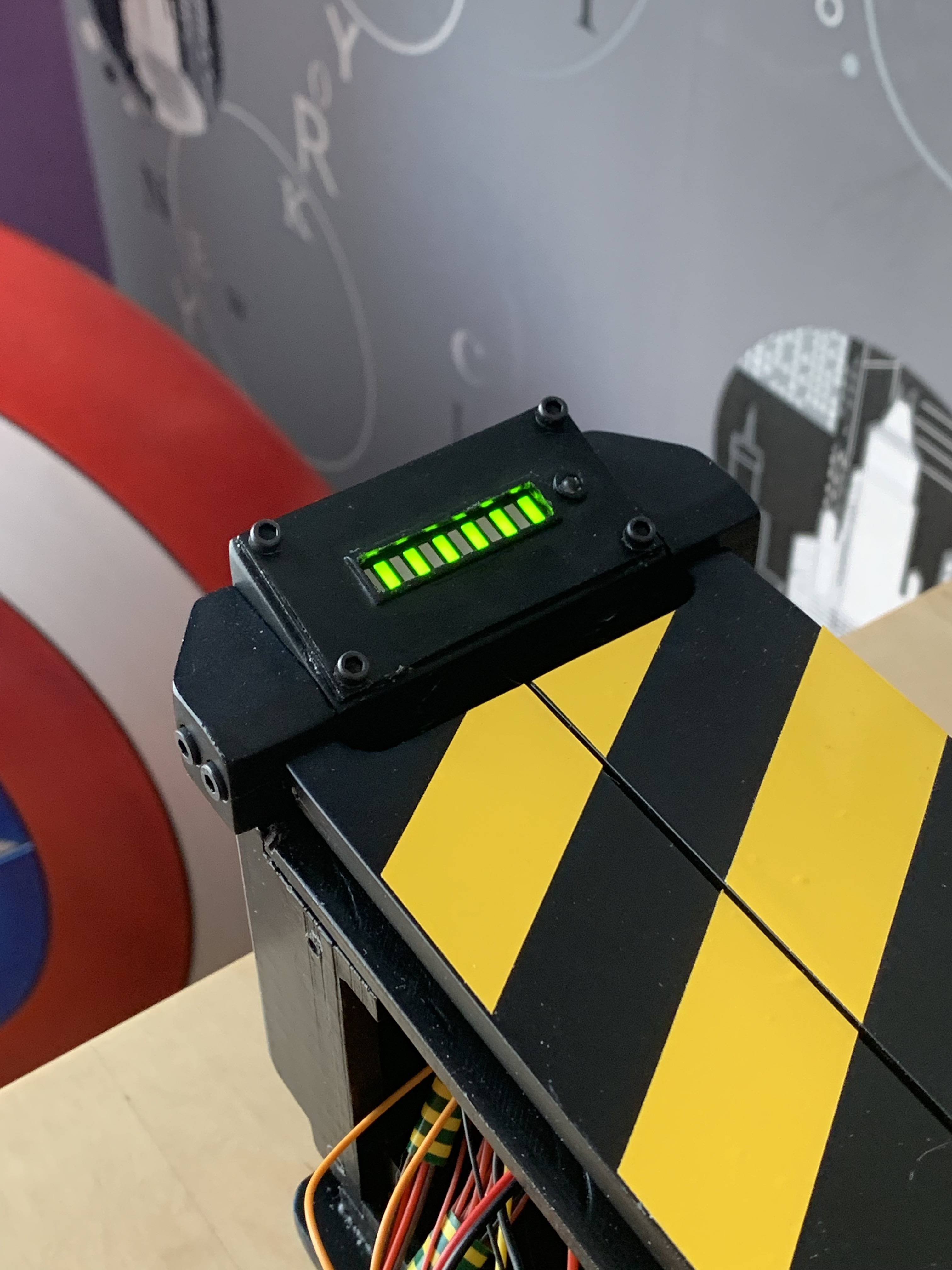
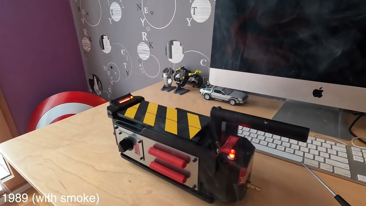
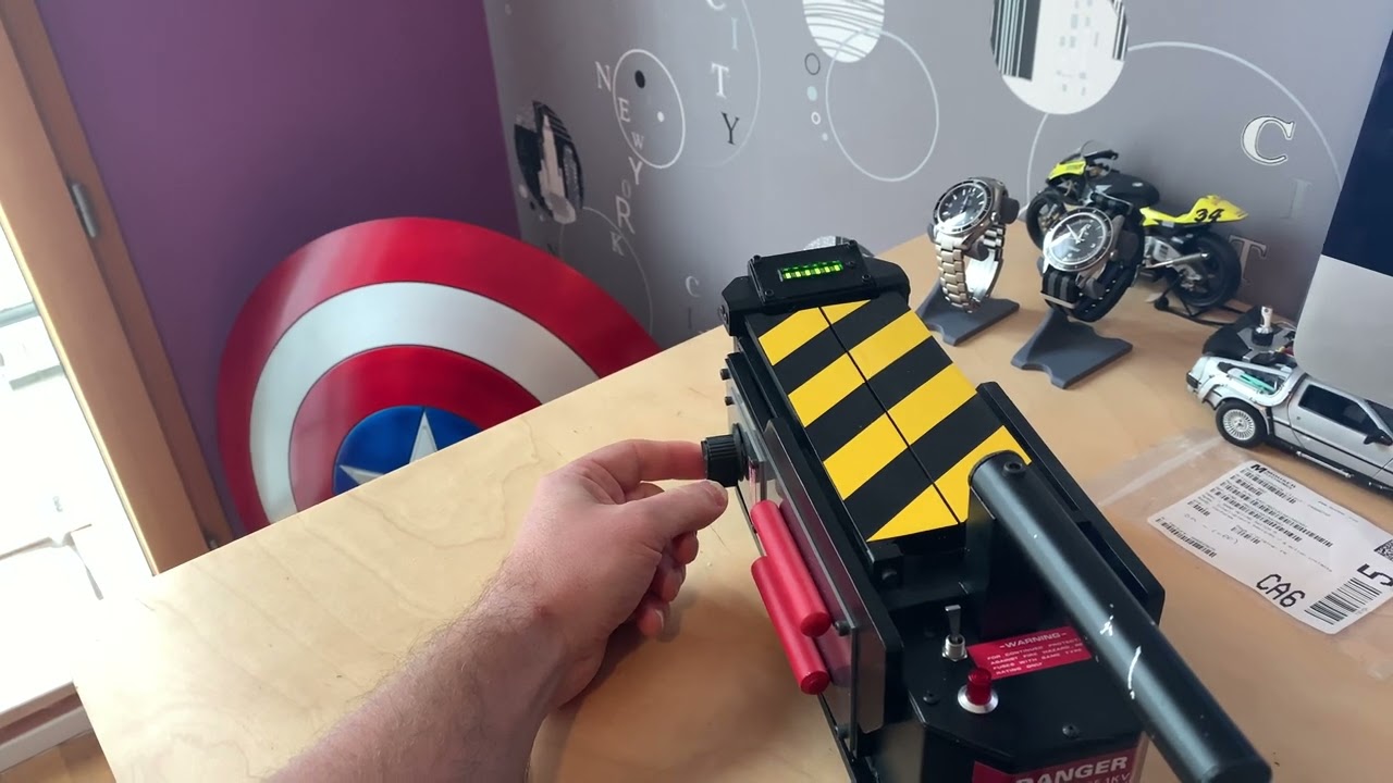
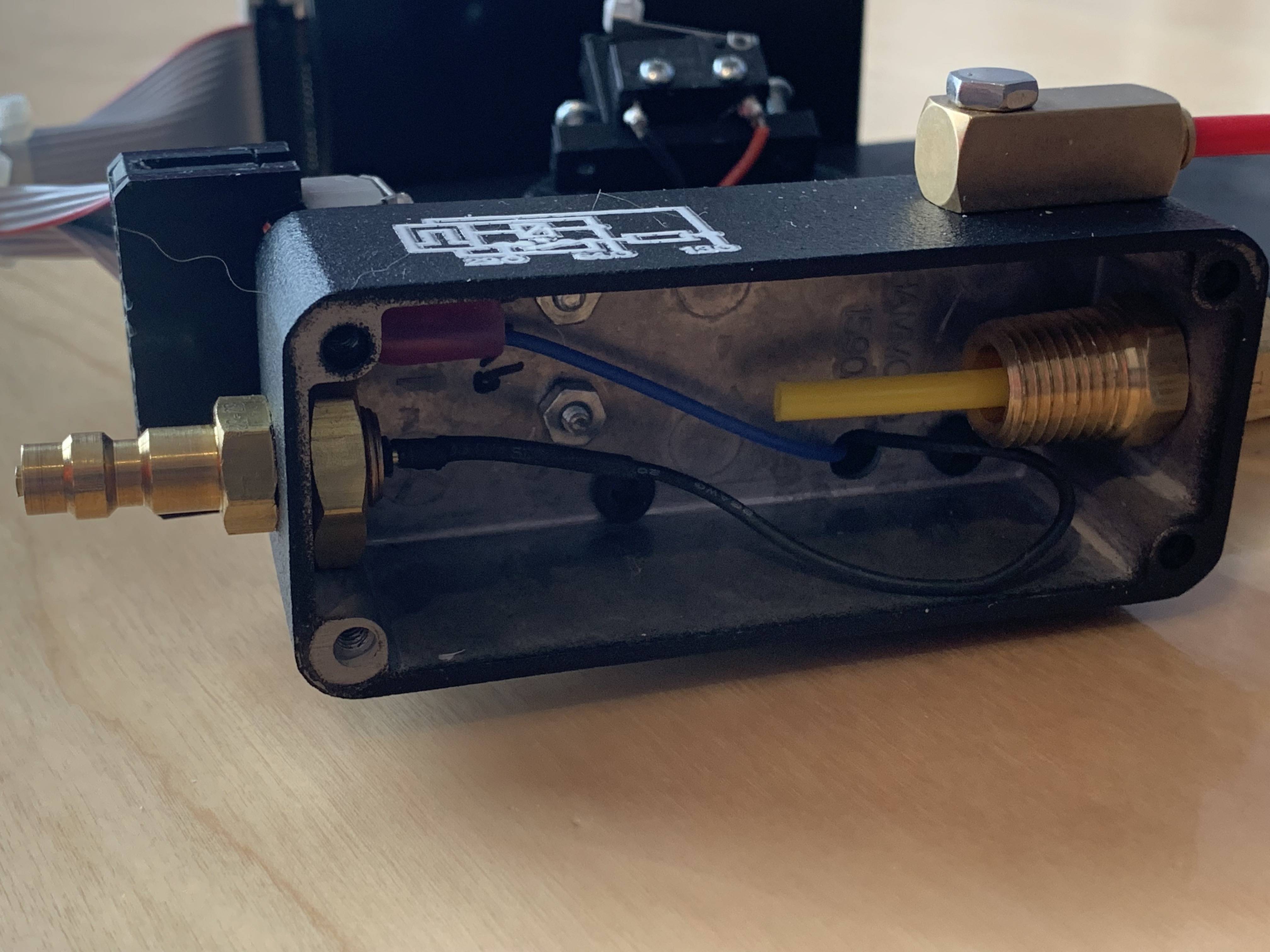
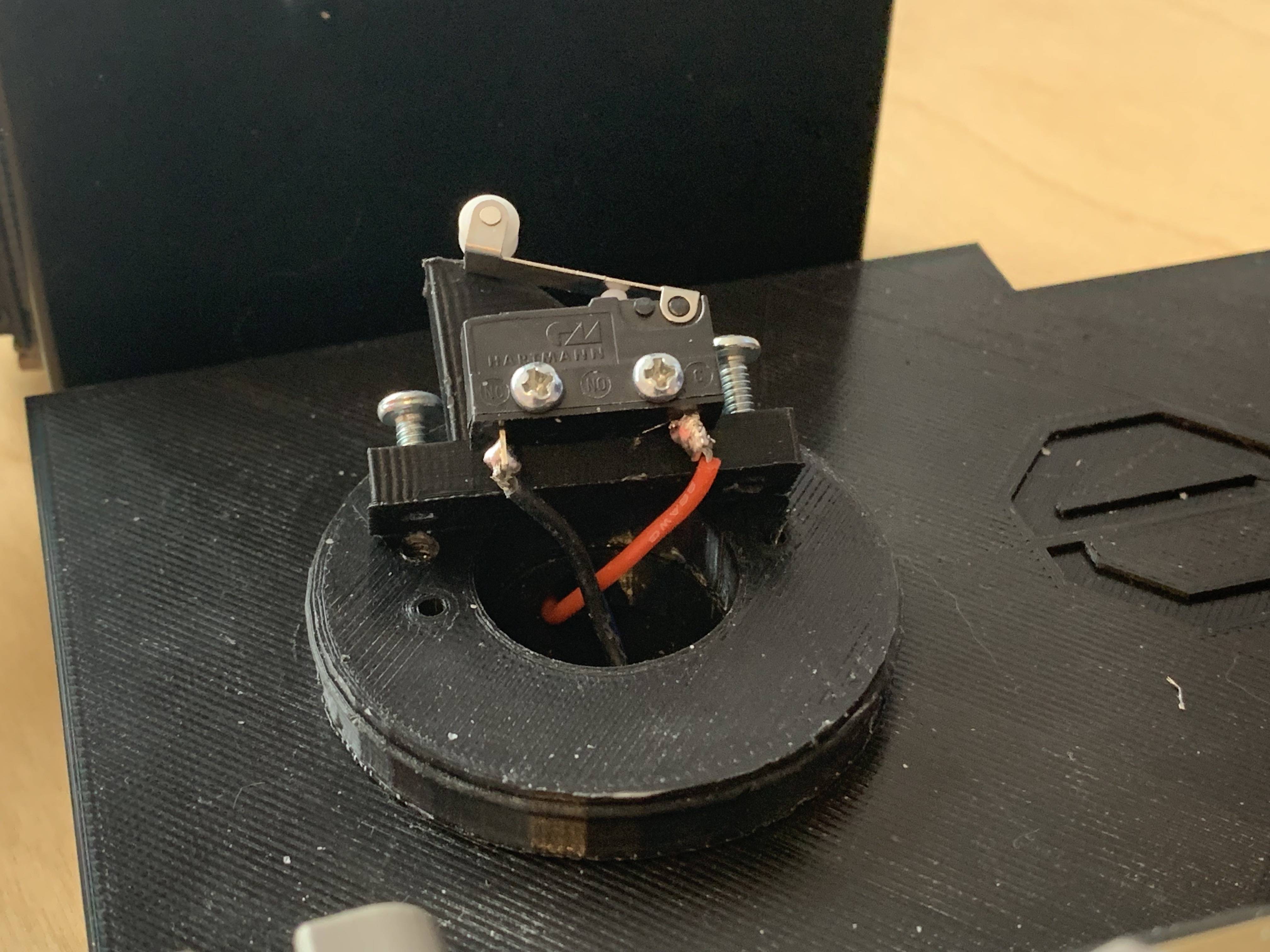
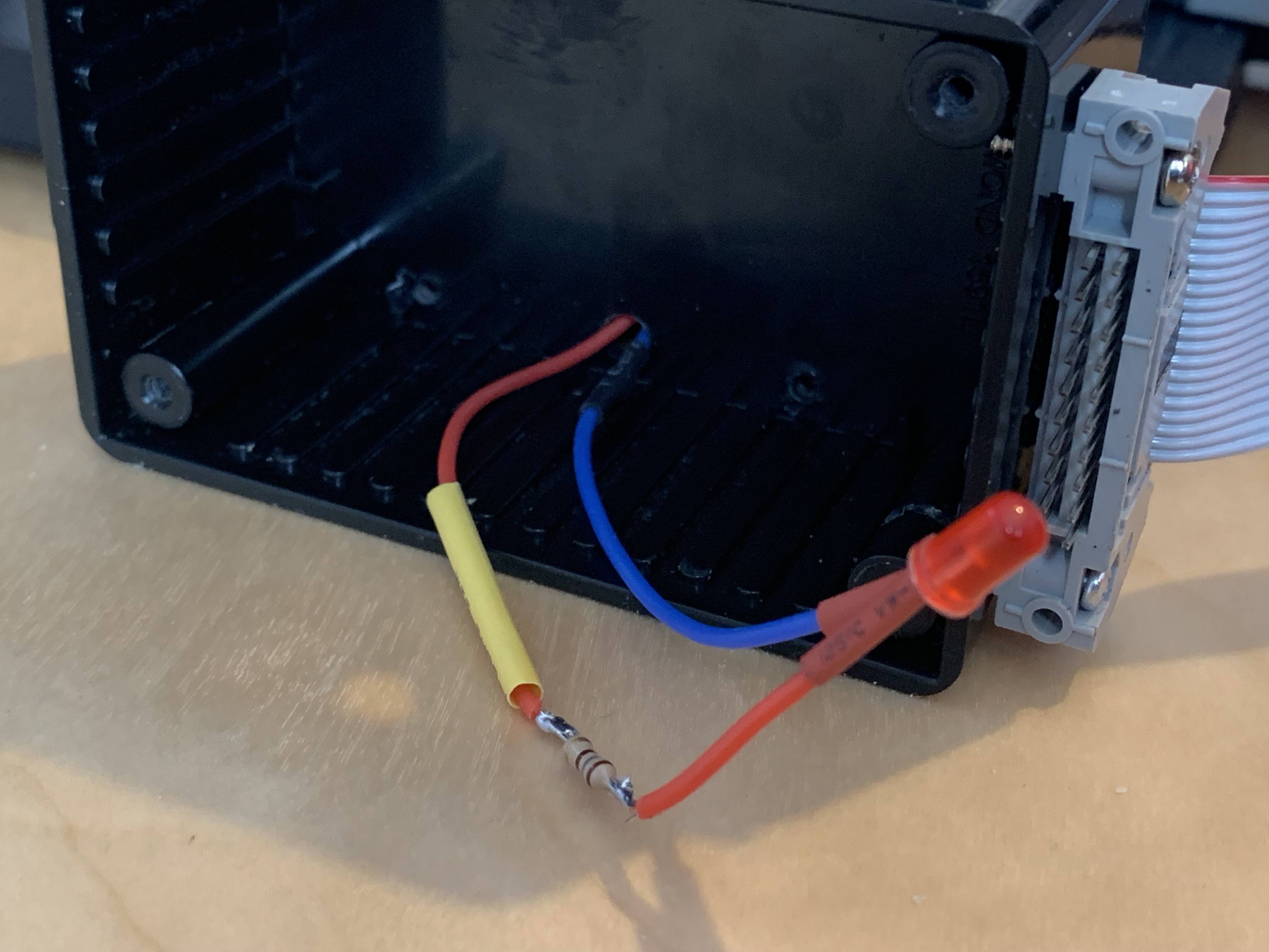
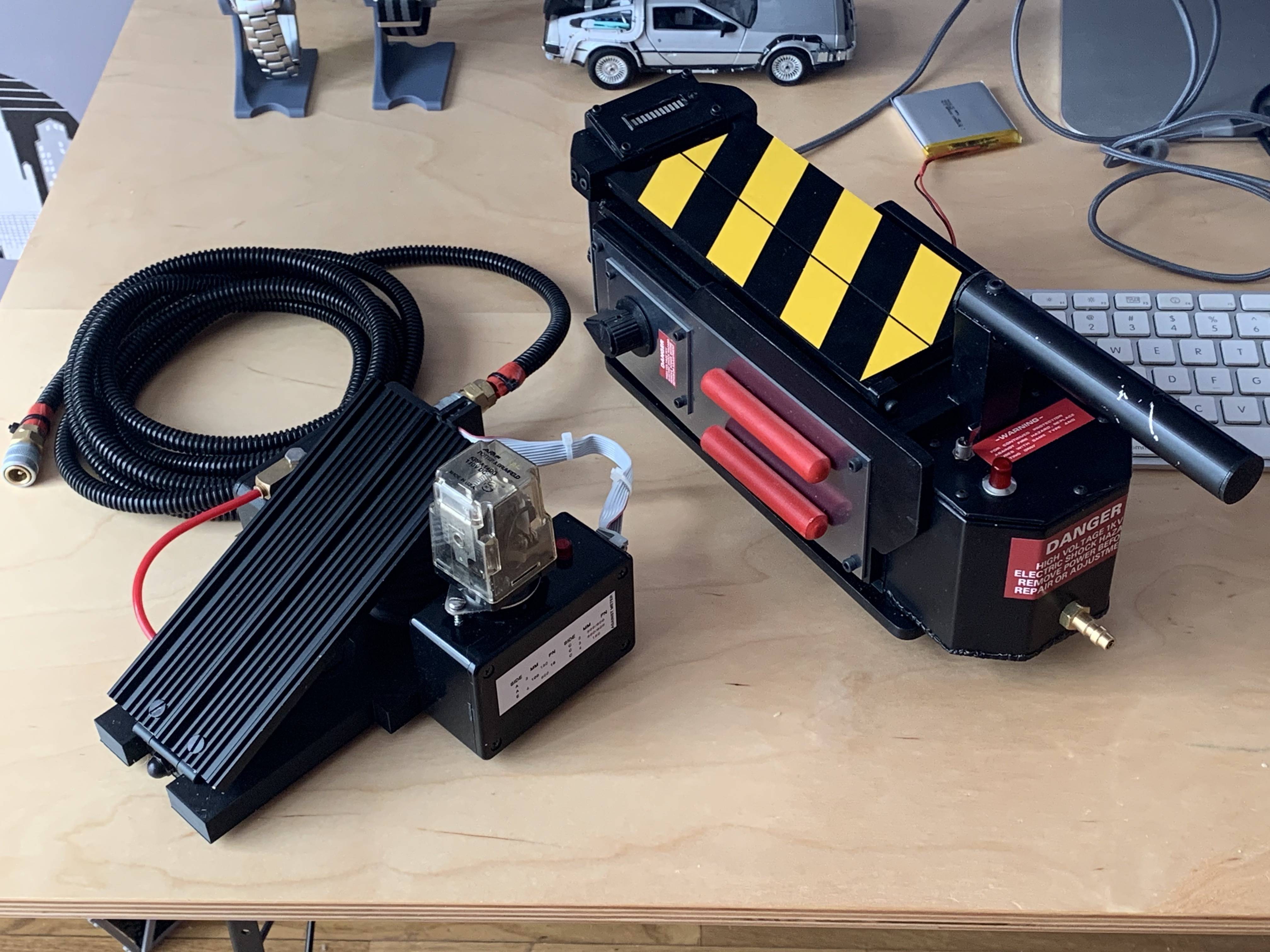
Alright, here is the end product:
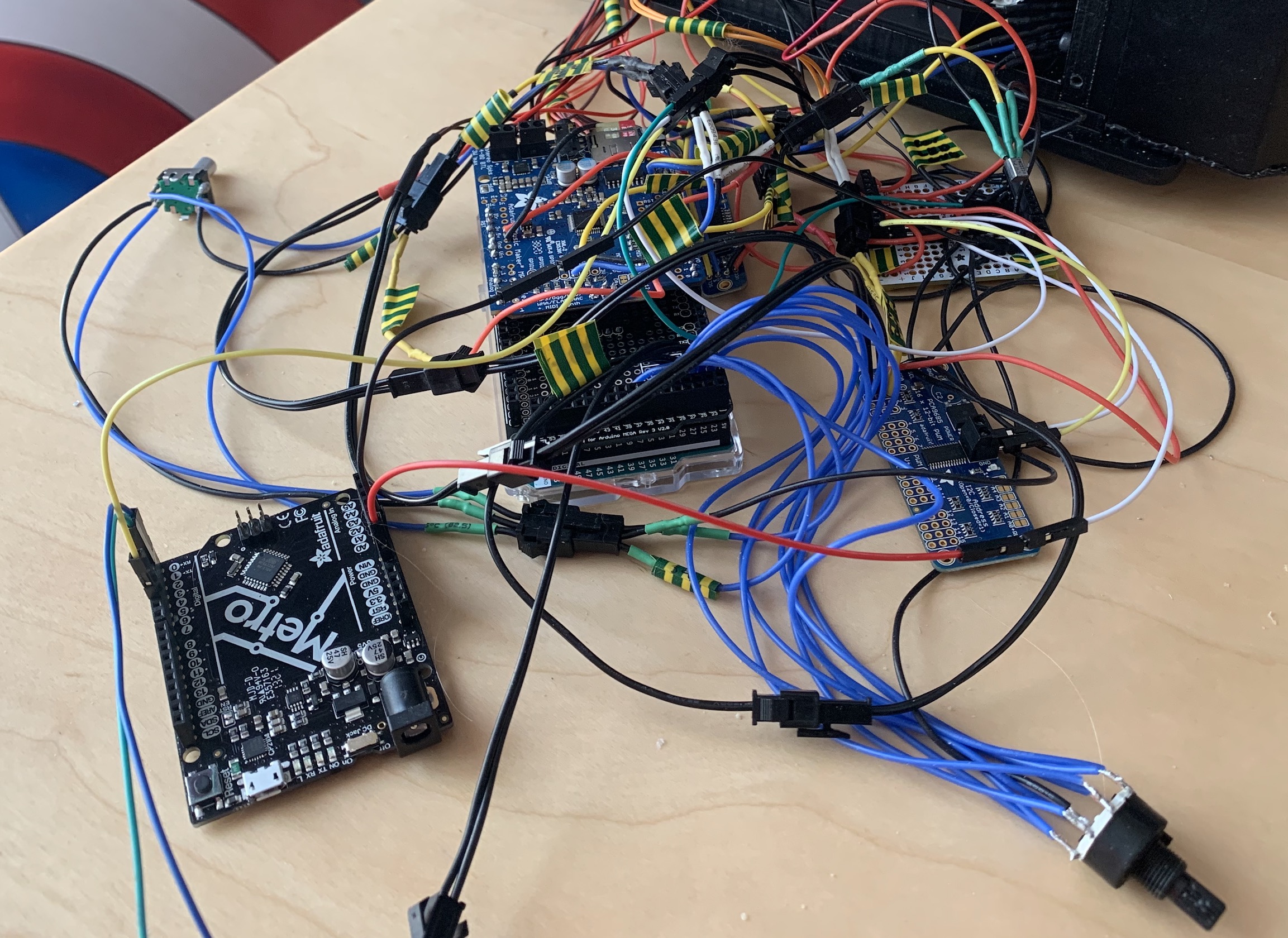
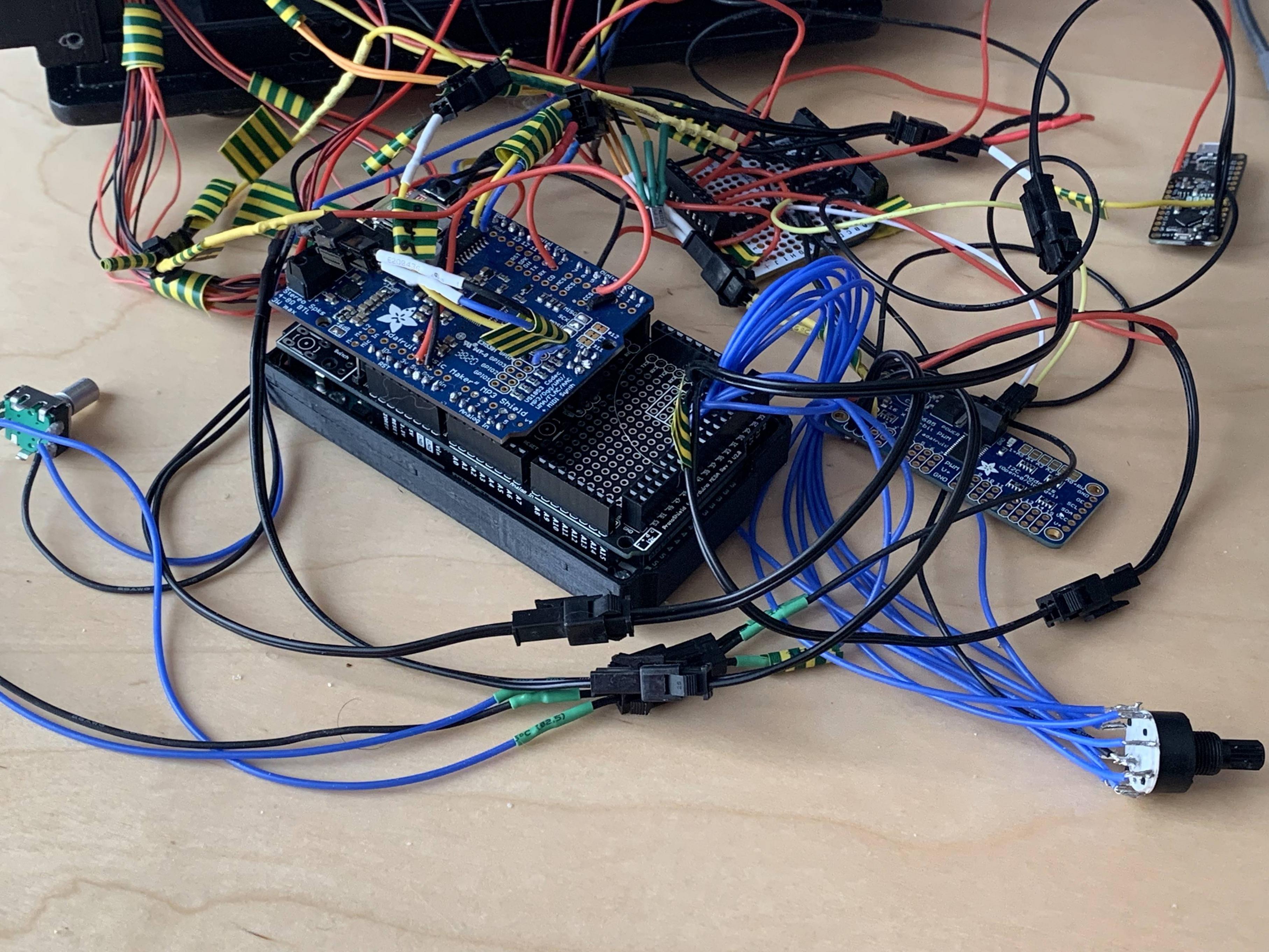
This has been created with the following micro controller setup:
Arudino Mega (I stack a Mega protoshield (adafruit part# 192) on top of the mega (do not forget to solder the pins) and then a music maker on top of the protoshield.) I included in my link a STL file to 3D print to hold the Mega and give it a bit of ground clearance over the wheels and v-hook bolts. I cut the ends flush with the nuts on my v-hook to additional clearance.)
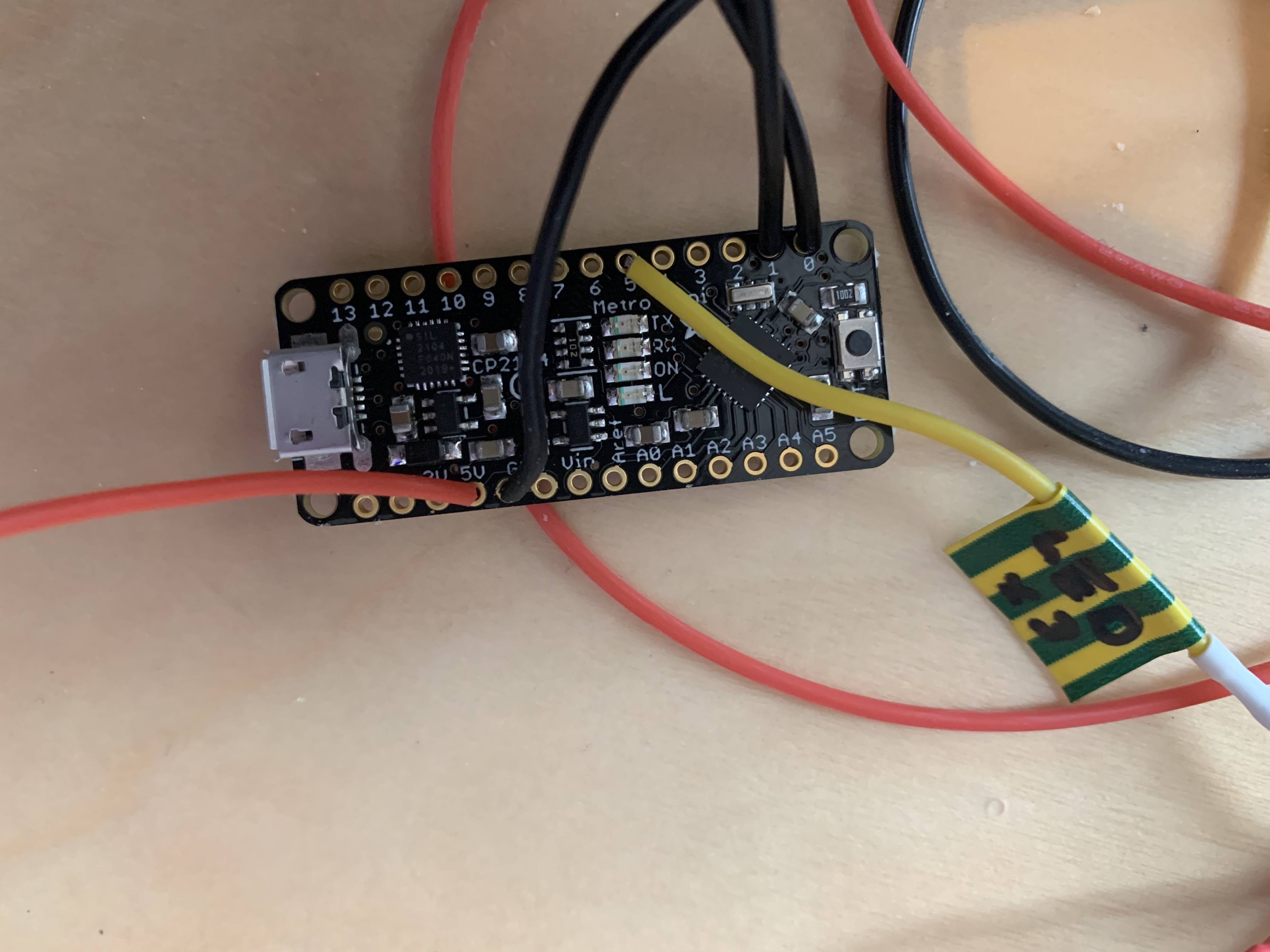
Adafruit Metro Mini (just a mini version of a Arduino Uno) (for the Adafruit NeoPixels)
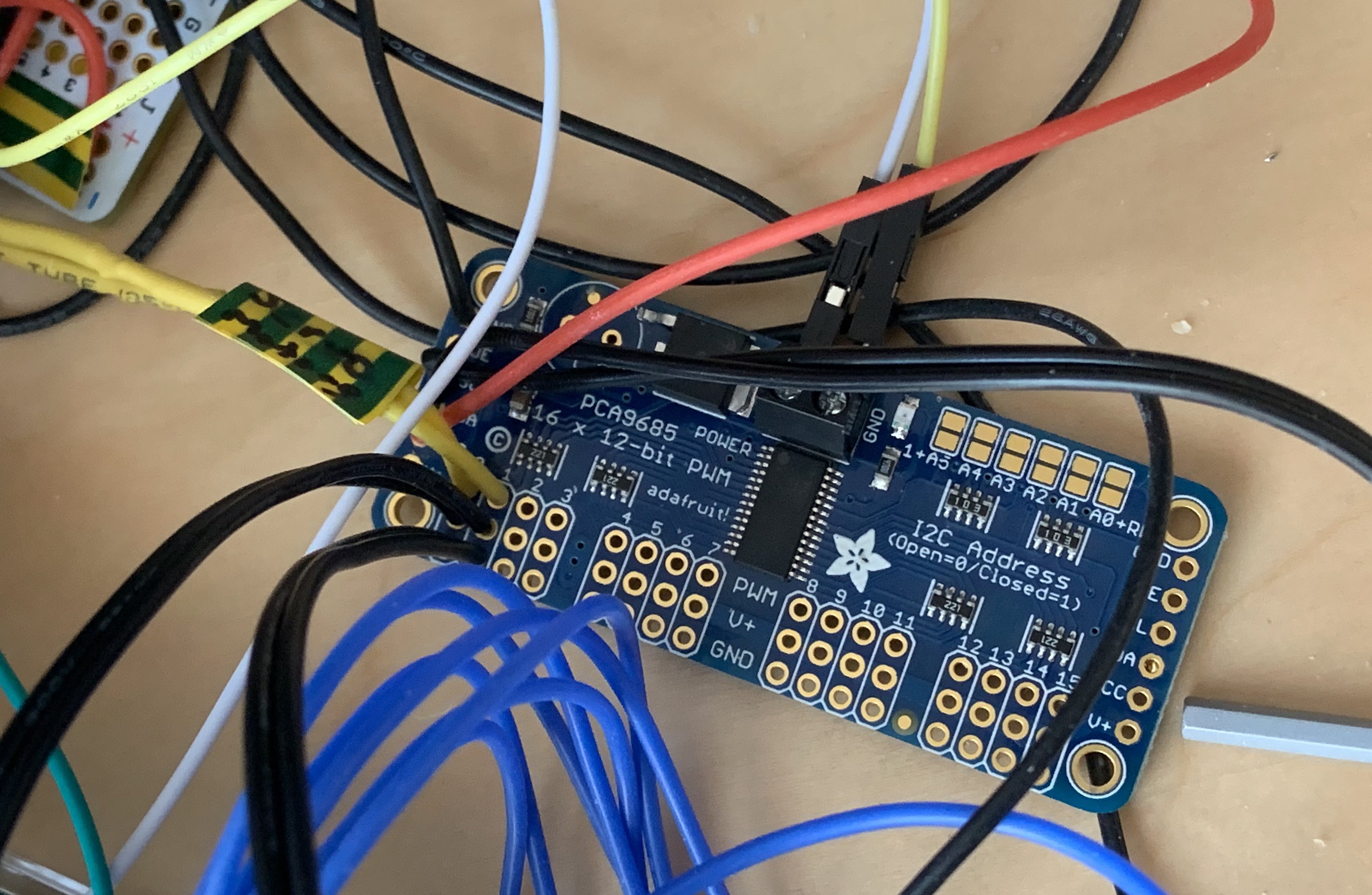
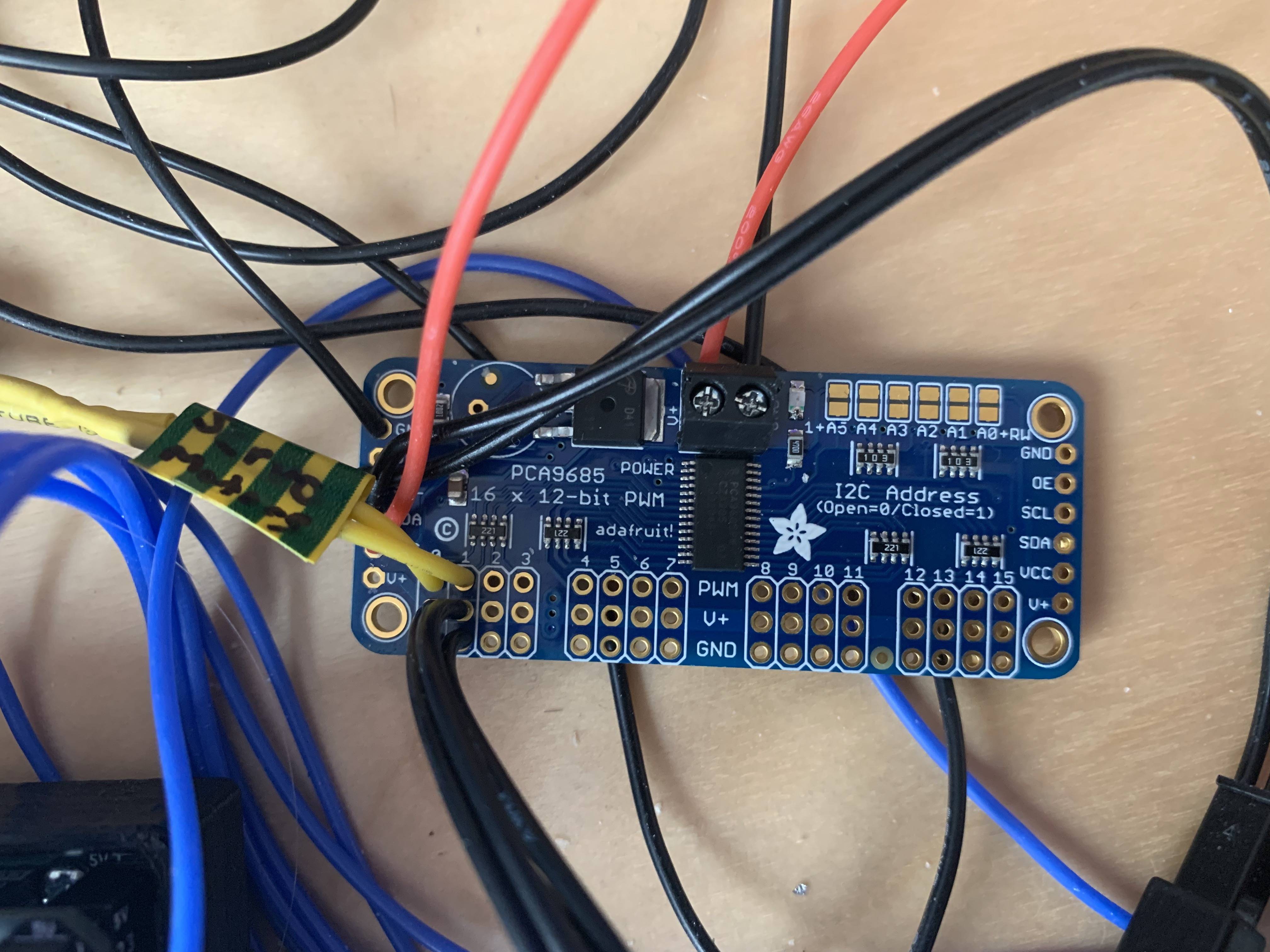
PCA9685 Controller (for the servos)
******* WIRING CHANGES FROM CHARLESWORTH DYNAMICS ORIGINAL GHOST TRAP GUIDE *******
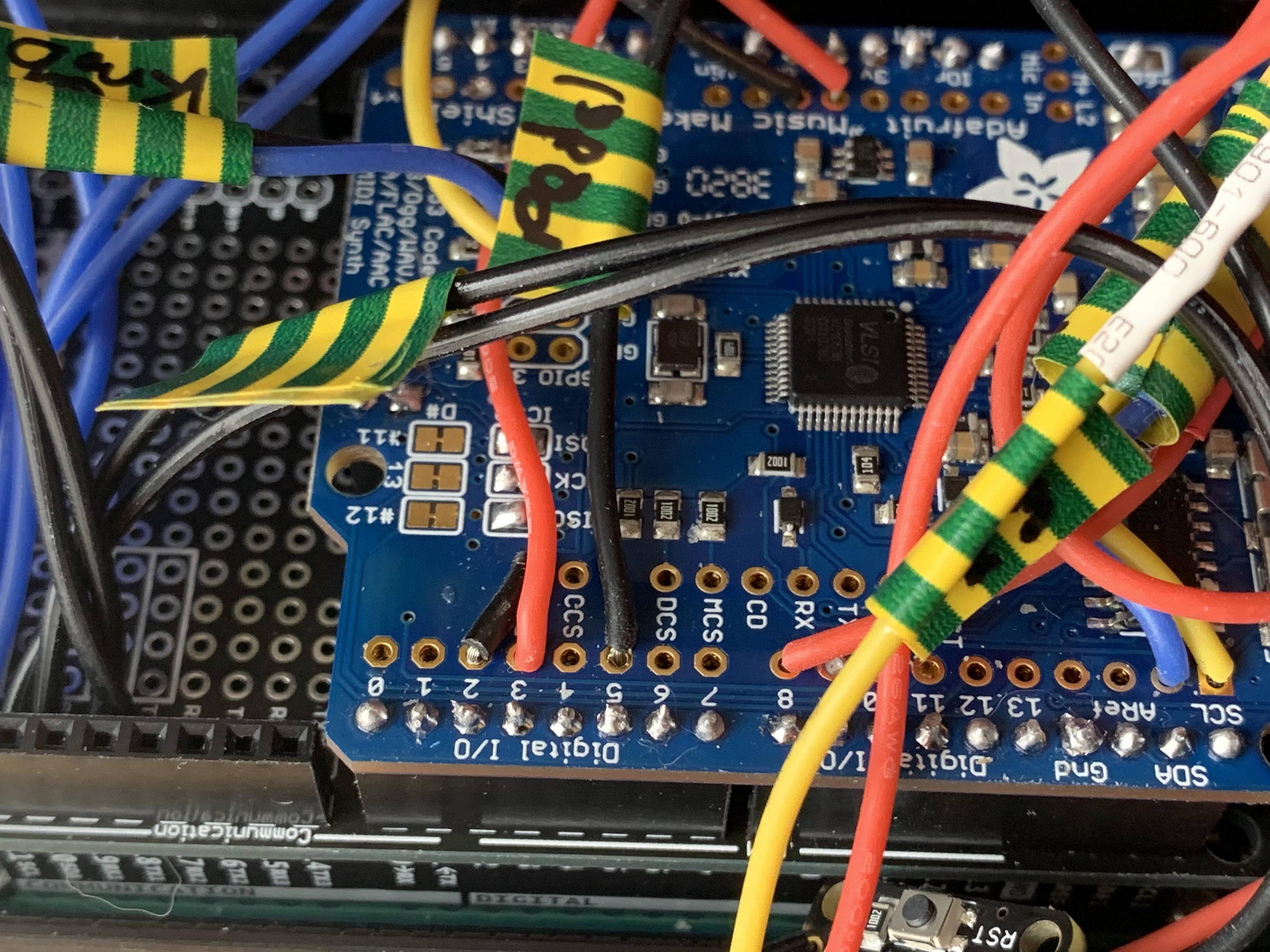
Yellow LED: Move to pin 8 on the music maker shield.
Bargraph pins: yellow and blue wires on analog 5 and 4 get moved to: (yellow) → SCL on music maker. (blue) → SDA music maker.
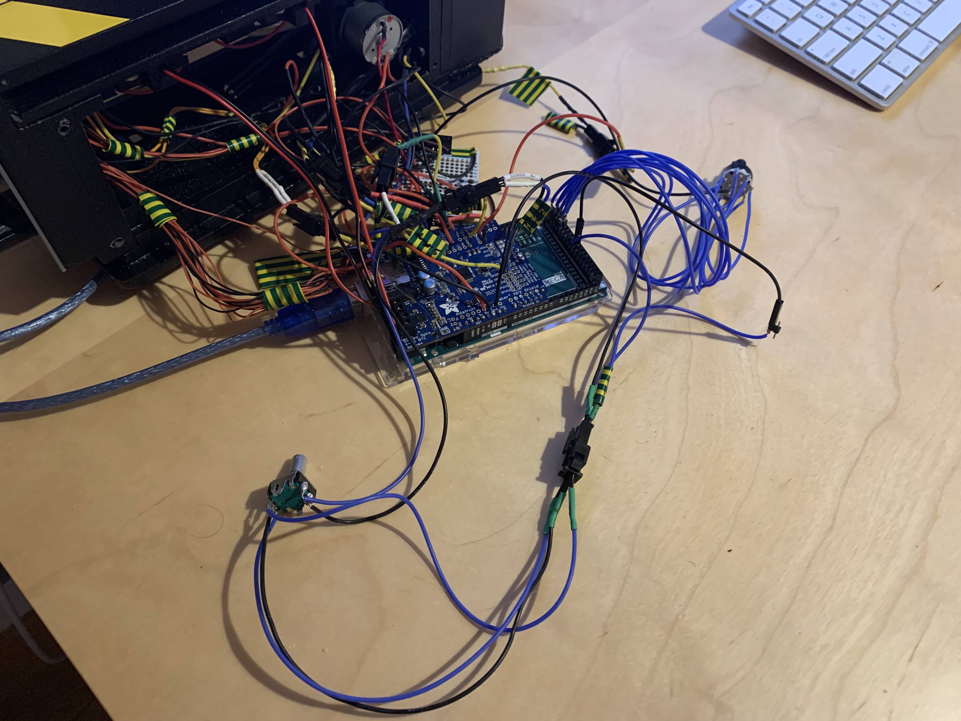
Rotary encoder (if you need one: adafruit part #377): Make a new 3 pin plug: middle pin goes to ground. The 2 outside pins: When viewing the 3 pins from the top (button side) of the encoder with the 3 pins facing north (top), the outside left pin goes to pin #39 and right side pin goes to pin #38. on the mega. The 2 pin side stays the same as CHARLESWORTH DYNAMICS updated guide.
8 way rotary switch from Adafruit (part #2925): connect to pins: 22 to 29 on the Mega. #1 pin on the switch goes to #22 pin work your way up to #8 pin on switch going to pin 29. Then centre pin goes to ground on the breadboard power/ground rail.
NeoPixels:
The Neopixel’s are control by a Metro Mini from Adafruit. The NeoPixels can conflict with anything that requires interrupts (random crashing and resets), such as the Servo motors and the music maker. This is due to how the NeoPixel library operates and turns off interrupts on pins.
The Mega will send commands over the tx channels to tell it what to do. Sometimes the mega will wait for a response back before it continues.
You can connect any Arduino board, it can be a Uno, Mini, Mega or whatever. It just needs to have a TX and RX pins and attach the NeoPixels to a digital pin.
For my example I did the following: NeoPixels connect to pin #5 on a Adafruit Metro Mini, and TX (mini: pin #1) to RX1 (mega pin# 19) and RX (mini pin #0) to TX (mega pin #18). Then run 5v and ground from the metro mini into the breadboard power/ground rails.
NeoPixel wiring: Follow Ectolabs guide of chaining them together. In a sense it goes like this: (I use a 3 pin plug) with the ground/5v power wires going to the breadboard power/ground rails and the other going to the Adafruit Metro Min pin #5:
Pin #5 on a Adafruit Metro Mini → 470ohm resistor → (NeoPixel #1) IN. (NeoPixel #1) OUT → (NeoPixel #2) IN. (NeoPixel #2) OUT → (NeoPixel #3) IN.
(NeoPixel #3) GND → (NeoPixel #2) OUT → (NeoPixel #2) GND → (NeoPixel #1) OUT → (NeoPixel #1) GND → GROUND (on the proto shield ground rail)
(NeoPixel #3) PWR → (NeoPixel #2) PWR → (NeoPixel #1) PWR → 5V (on the breadboard power/ground rails)
Servos:
The servos are controlled separately by a I2C PCA9685 controller, so they do not interfere with the NeoPixels and or the Music Maker. (no more servo twitching or crashing).
This needs to be connected to SDA and SCL on the Mega and the Left servo on PWM 0 and Right servo on PWM 1. If you switch it up, just change the pin settings in the code.
Connect 5V and ground on the I2C to the breadboard power/ground rails (This only powers the board and not the servos).
Then I run a separate 5v and ground on the middle/top of the PCA9685 with 2pin terminal block to the breadboard power/ground rails. This only powers the servos and not the PCA9685 controller. Then wire the servos power and ground to the appropriate V+ and GND pins under the PWM pins.
Music Maker:
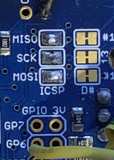
Before attaching to the Mega, you need to connect the MISO, SCK and MOSI on the ICSP side. Optionally you can cut the #11, #12, #13 connectors next to them to free up those pins on the Music Maker, but it is not required since we do not use them.
Rear red LED is moved from analog #1 pin to digital i/o #3. This could also be moved to pin #6 as well as #3 is a interrupt pin which by default is used by the DREQ on the Music Maker. However the original guide had us move the DREQ to pin #2 on the Music Maker so I just left my rear red led connected to pin #3 as it was unused. If you do not follow the original guide, I would leave DREQ on the music maker shield at the default #3. Then just change the DREQ pin number to 3 in the code.
NOTE: Connect the db+12 and db+6 on the music maker to prevent the hissing sound during the bootup sequence. This will make the trap louder but you can always adjust volume. I prefer it loud to help hide the smoke pump motor while in smoke capturing modes.
NOTE: When using the music maker with +12 and +6db, at max volume, basically anything less than 40 volume level can crash the arduino if you are powering it by USB only.
if you plug in your battery to the power booster and flip the power switch on, it will solve the problem (even with usb still plugged in).
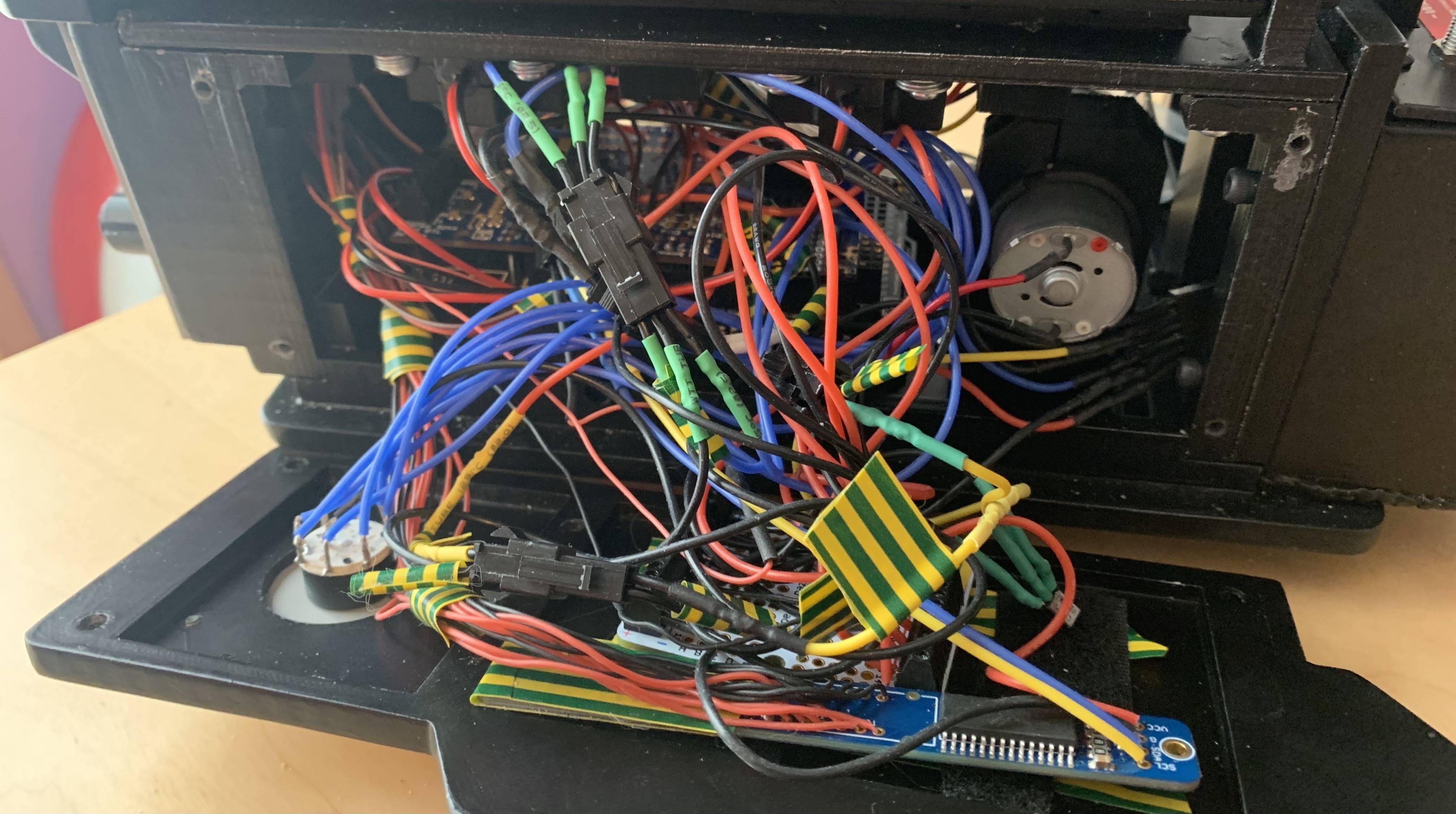
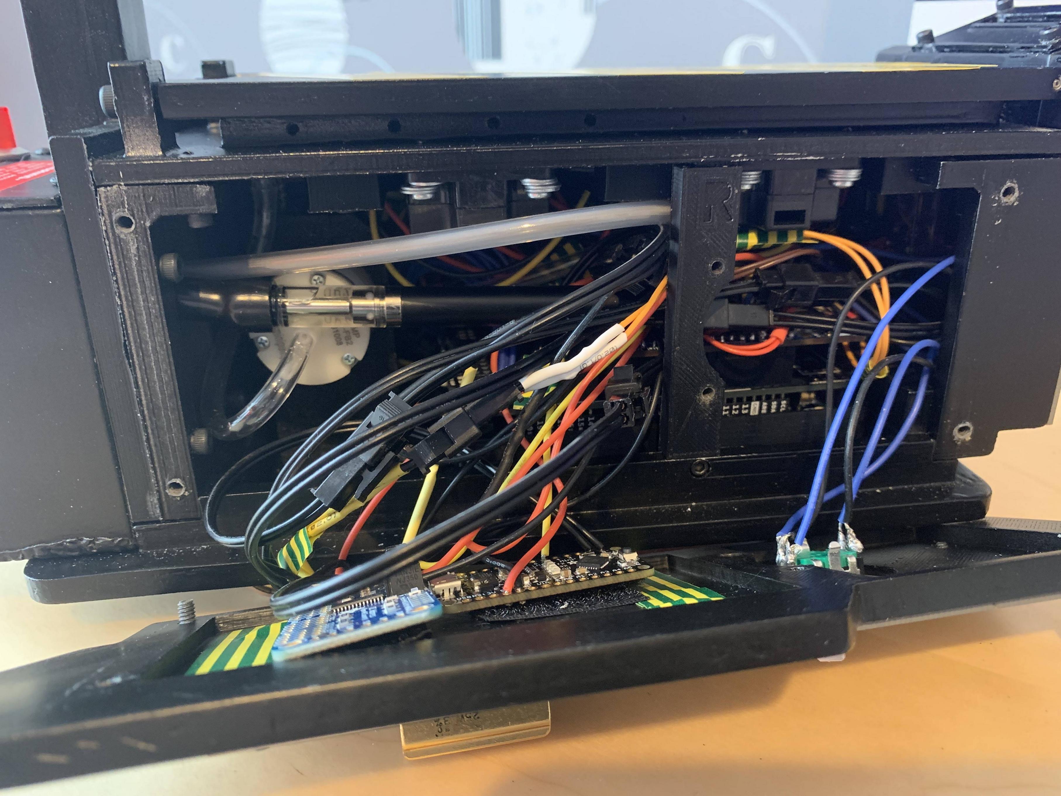
When installing into the trap, I keep the PCA9685 servo controller and Metro Mini attached on to the right wing. It looks like it is a tight fit but there is still some space.
Link to files: