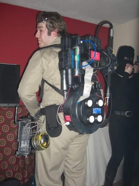
Long time lurker. This is my third pack build. The second one was about 8 years ago and I look back on it with a lot of regrets. It was just a quick three day build for Halloween but I still followed Stefan’s plans and it could have been much better.
My other build was made with no really plans or knowledge in an evening and isn’t worth showing. Both are only significant because they triggered my maker hobby and set me on the path to building so many of my favourite props from films I love.
After this last Halloween I felt like it was time to revisit the proton pack and get it as good as I can for as cheap as I can. So still using Stefan’s plans and still card. Mostly.
I wanted to take my time with this build as the previous ones were made to a deadline and while I do excel at that kind of timeline I wanted to build this pack at my leisure.
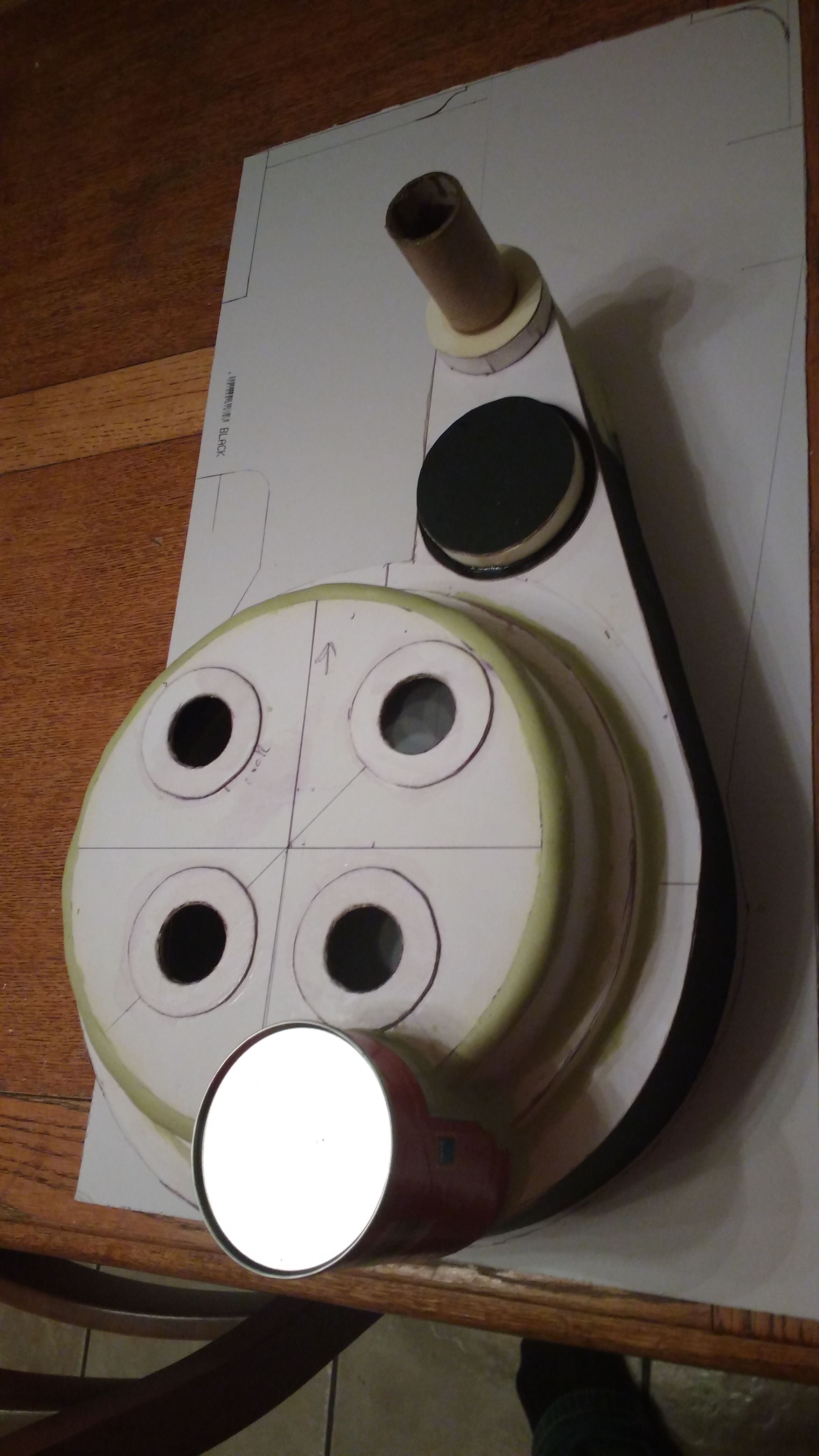
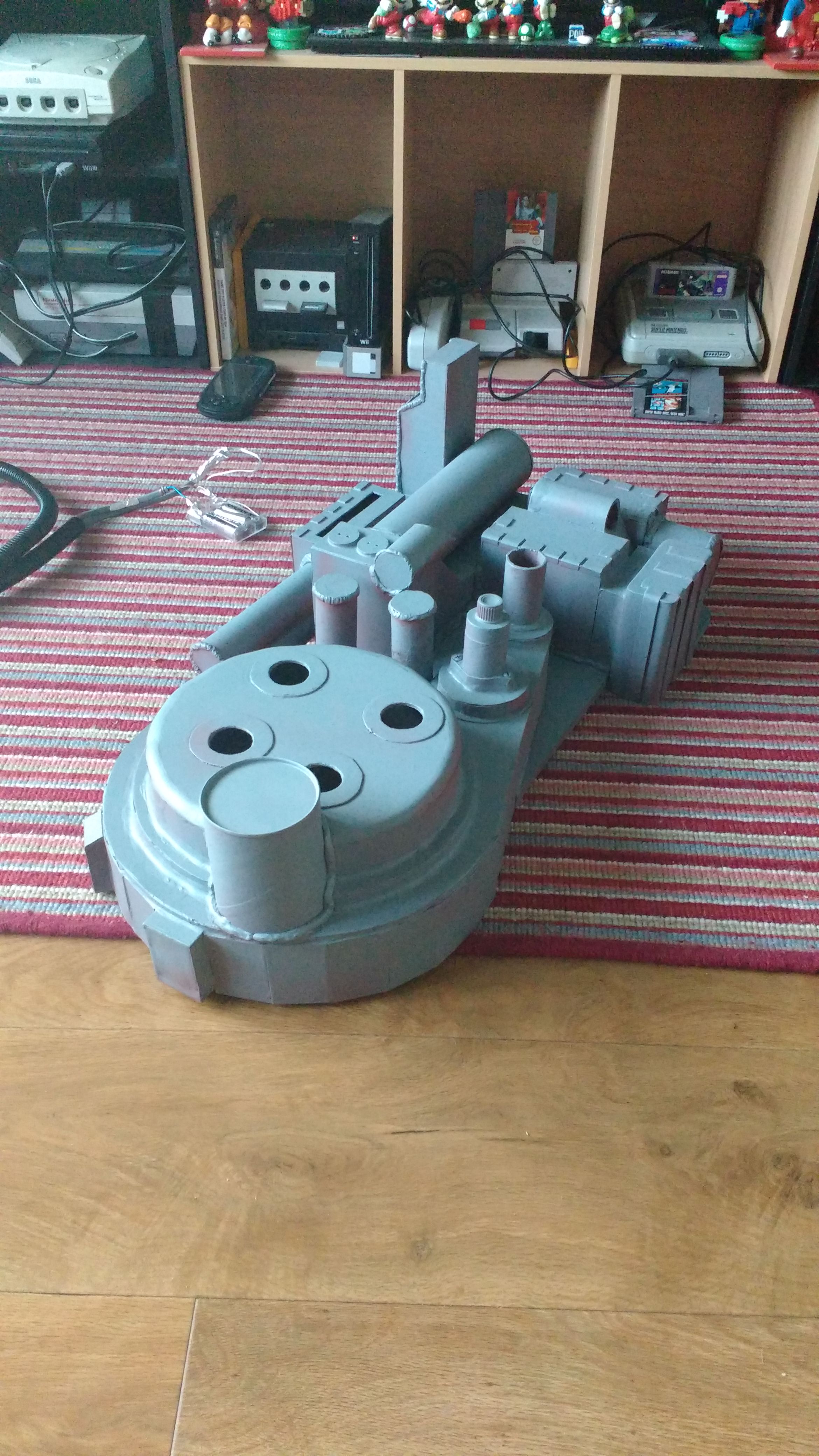
I took pictures as I built this pack but not every part of the build is chronicled here we have the motherboard outline, spacer, cyclotron and n-filter. Made out of mounting board and a Pringles tin.
As you can see I made the curve of the cyclotron edge by building it with a step like indent and then filling it with two part epoxy. I’ll be using epoxy throughout to strengthen the inner walls of the pack and fake welding joints. For load bearing parts of the pack I’ll be using some wood inserts.
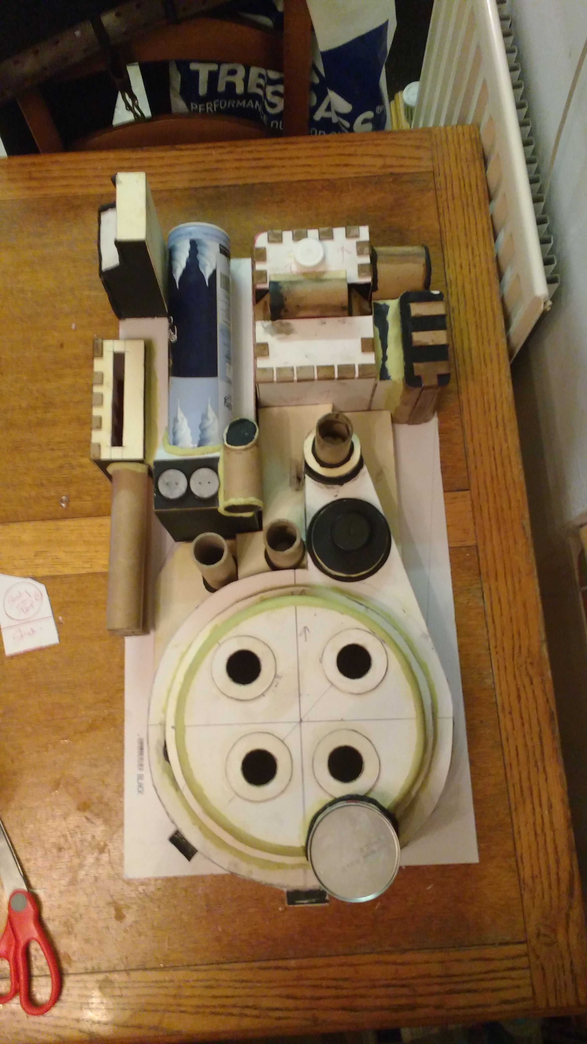
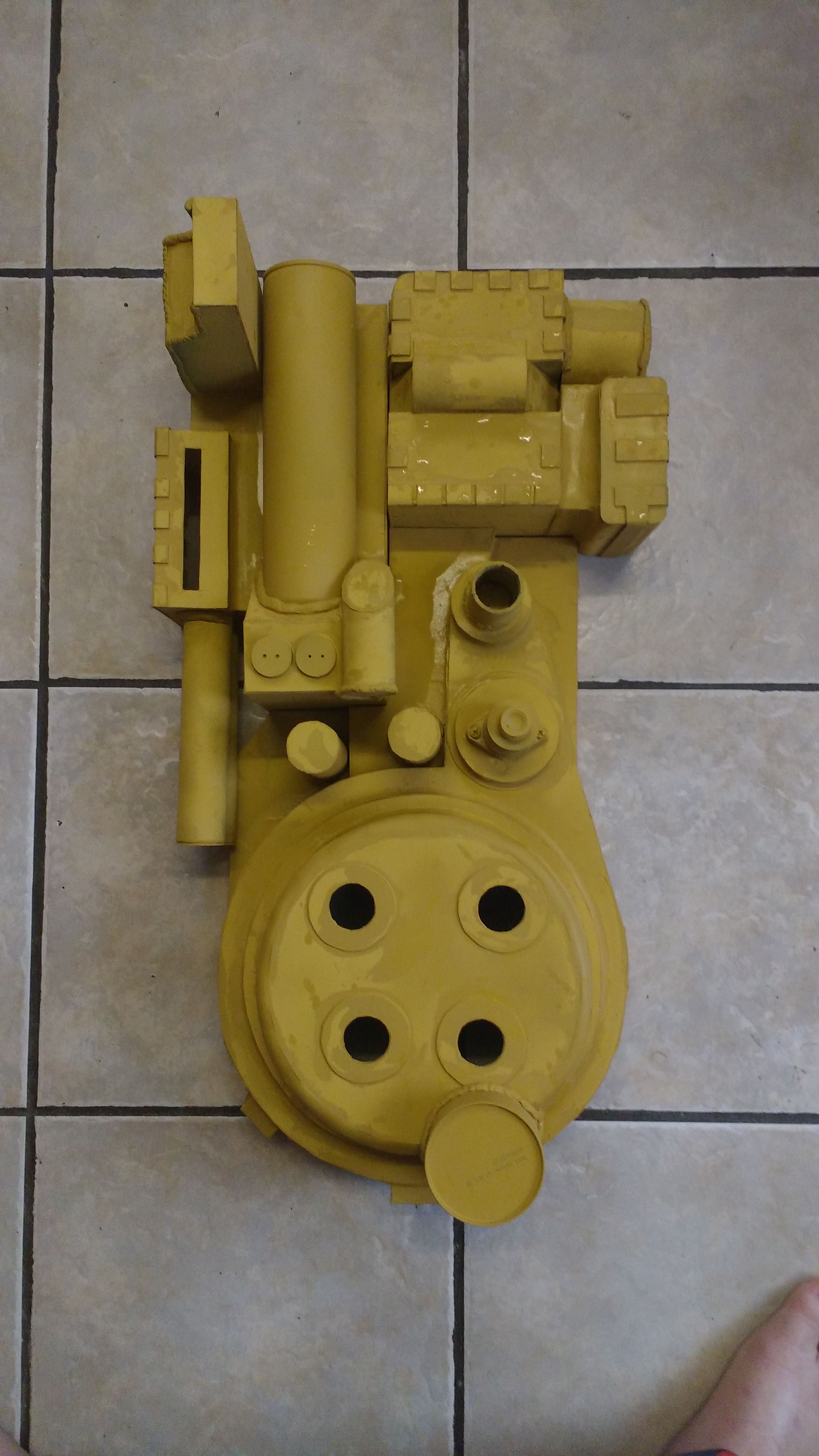
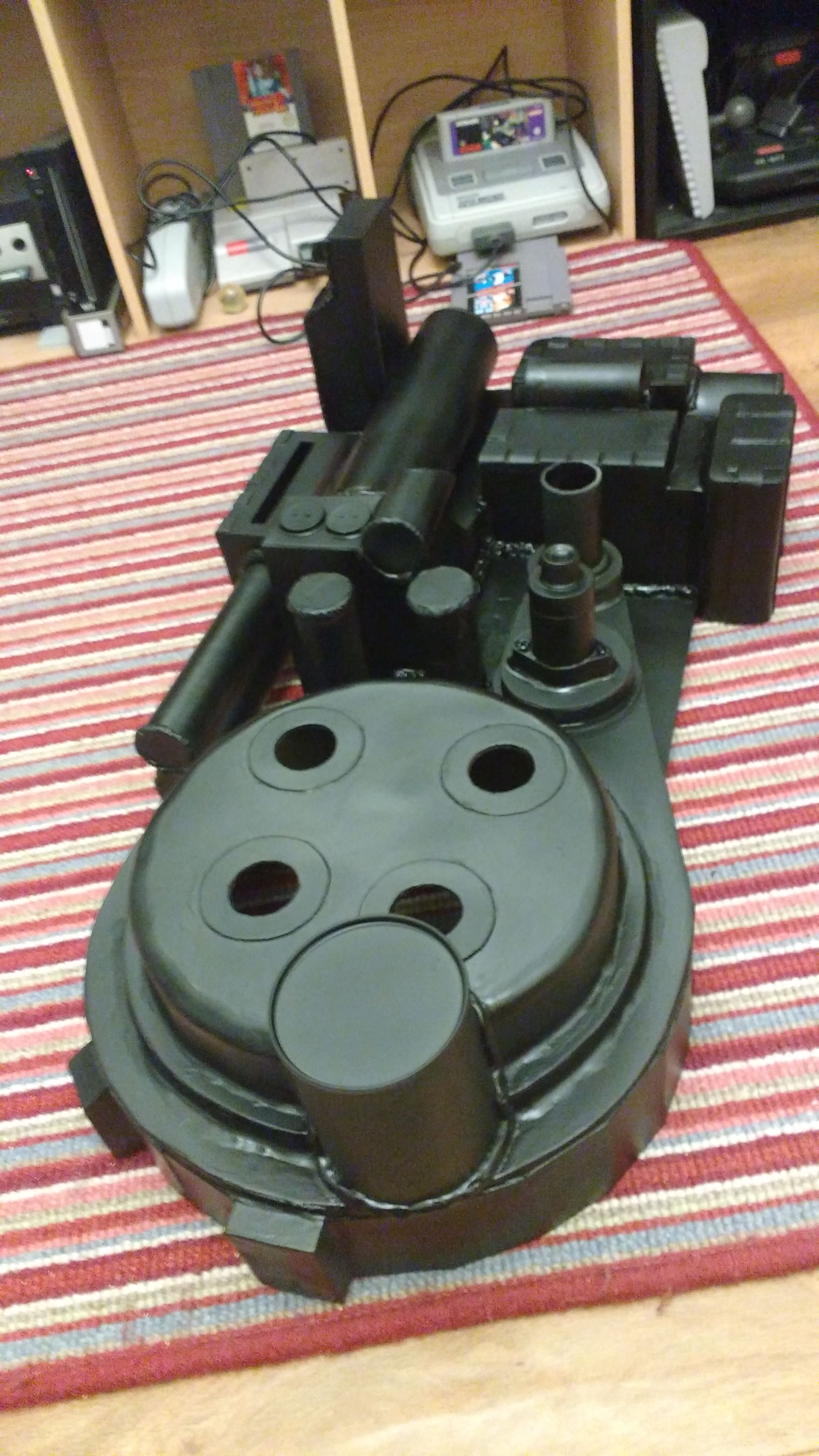
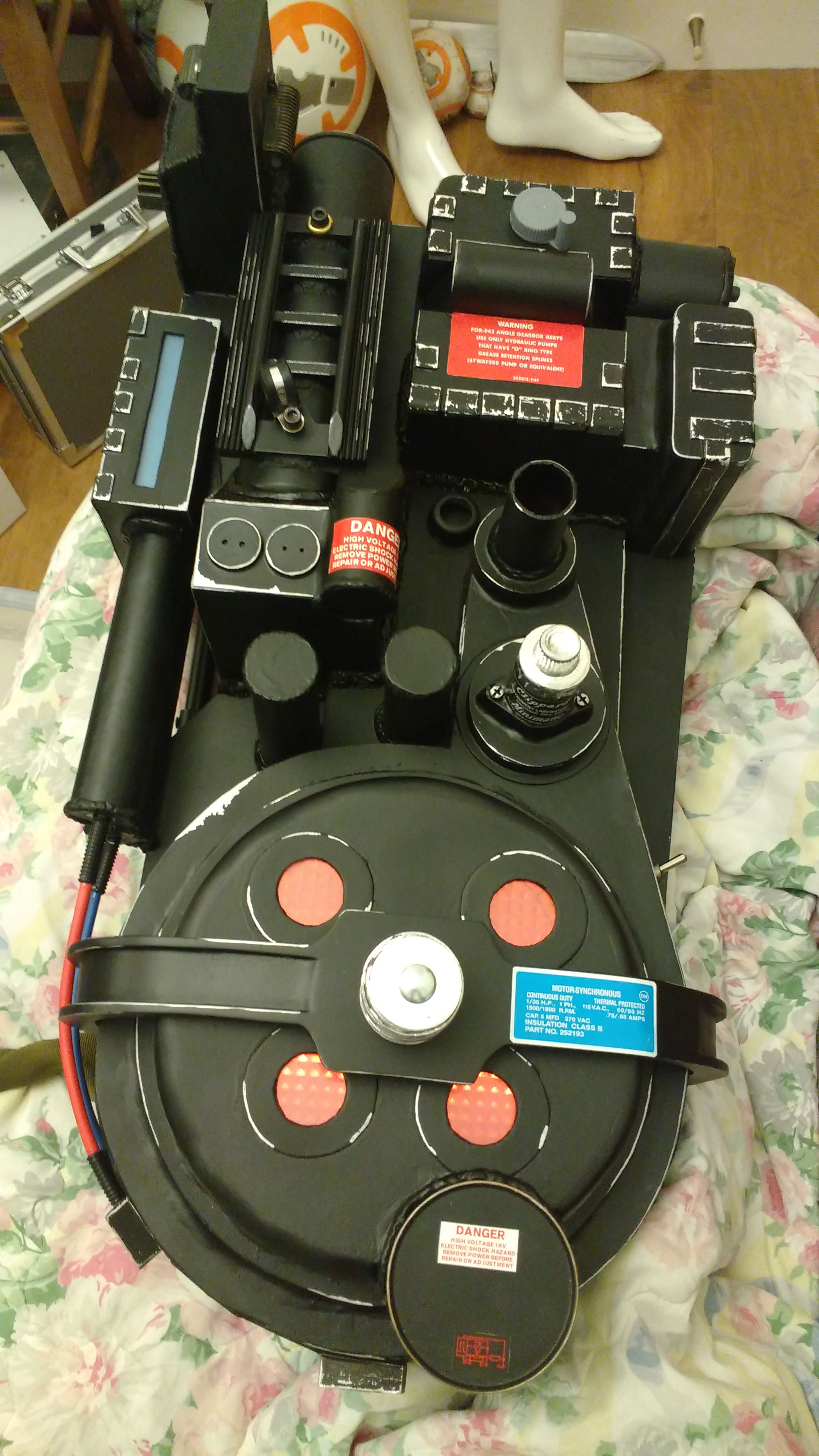
Here we have a pretty big jump (sorry). The booster and EDA, the gearbox, the ion arm, wand mount, PPD, HGA and the plating are all added.
I broke the pack down into areas grouped around the spacer, the booster and the gearbox. Each of these sections took an evening to fabricate. The wand mount has a wooden core to attach the wand clip more securely.
I cheekily used a whipped cream spray can and HGA is a spray can lid
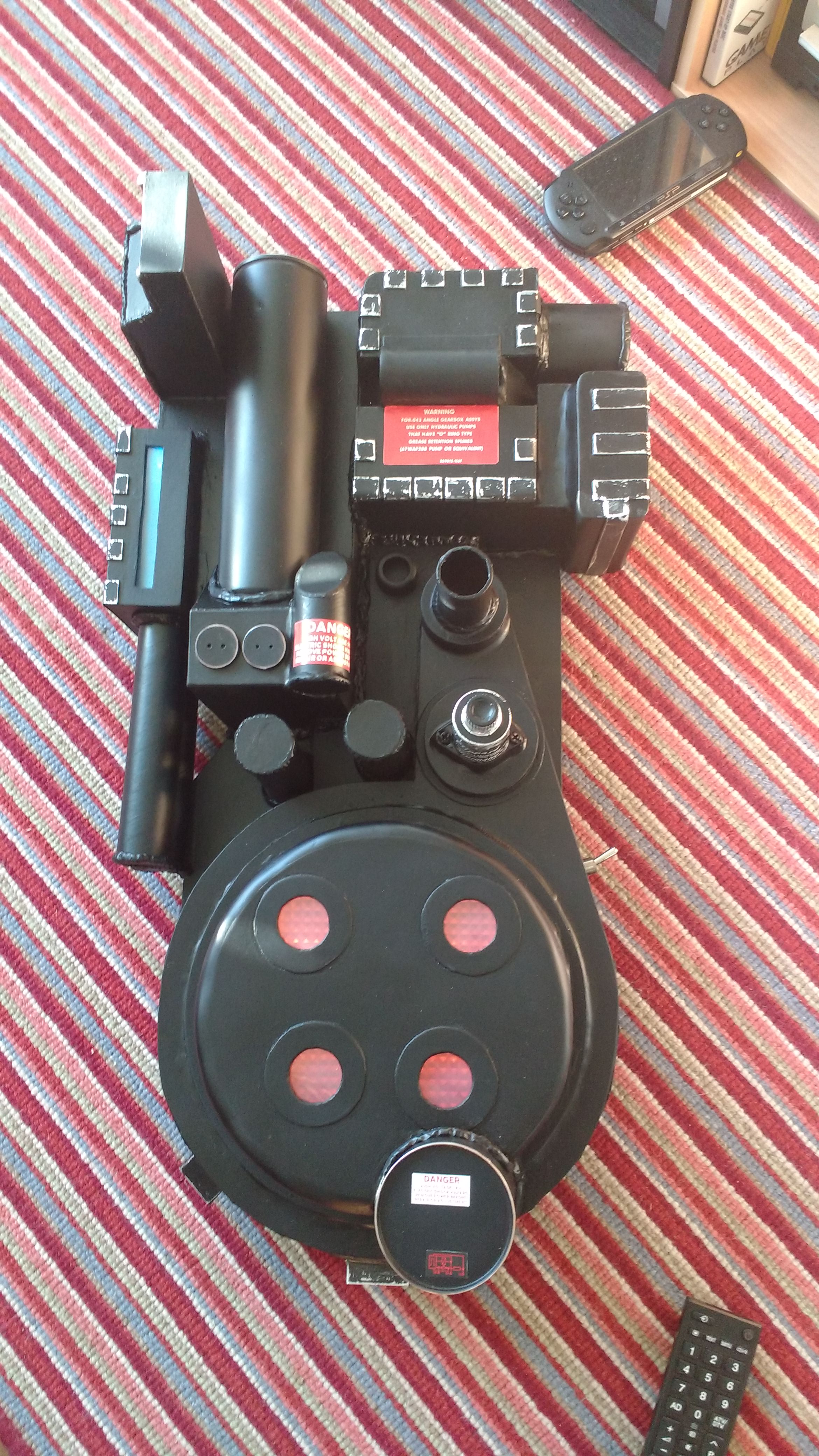
The electronics cost me about £10. I got a battery powered led sticky back strip and a cascading icicle light for the booster. By turning the icicle upside down it look pretty close to how it should. I learnt to solder and added the icicle into the led strip circuit while also halfing the number of lights in the original circuit and then added a metal flip switch. Here’s the part where I make deviations from screen accuracy by added the switch to the spacer at a point where I can flip it whilst wearing it.
The lights are all white and the colouring is achieve with acetate.
I added a crank knob on the second image. To create the look of a metal undercoat I added some metal plumbers tape to certain areas of the pack and then sanded those to create the worn effect.
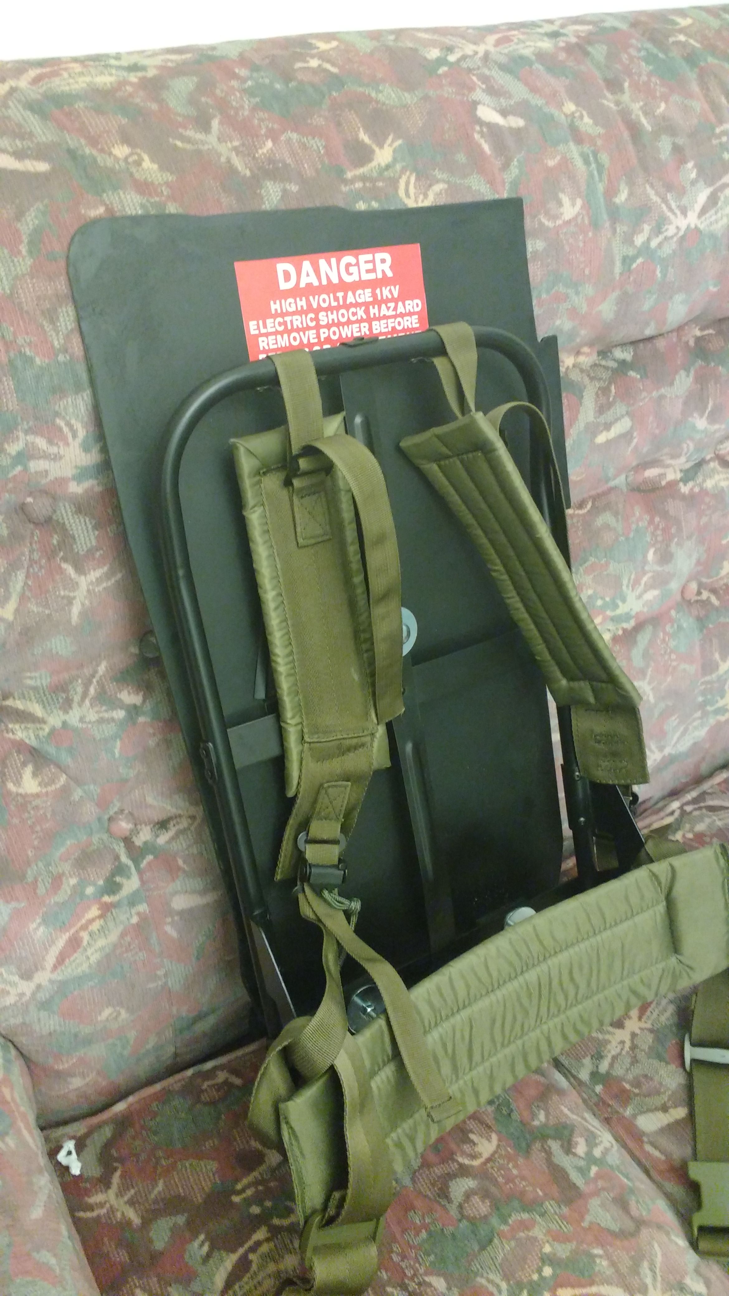
The alice pack arrived and I borrowing some ideas from Astyanax’s thread for connecting the frame to my motherboard. The board itself is four layers of mounting board glued together with a hole in the back for access to the light batteries.
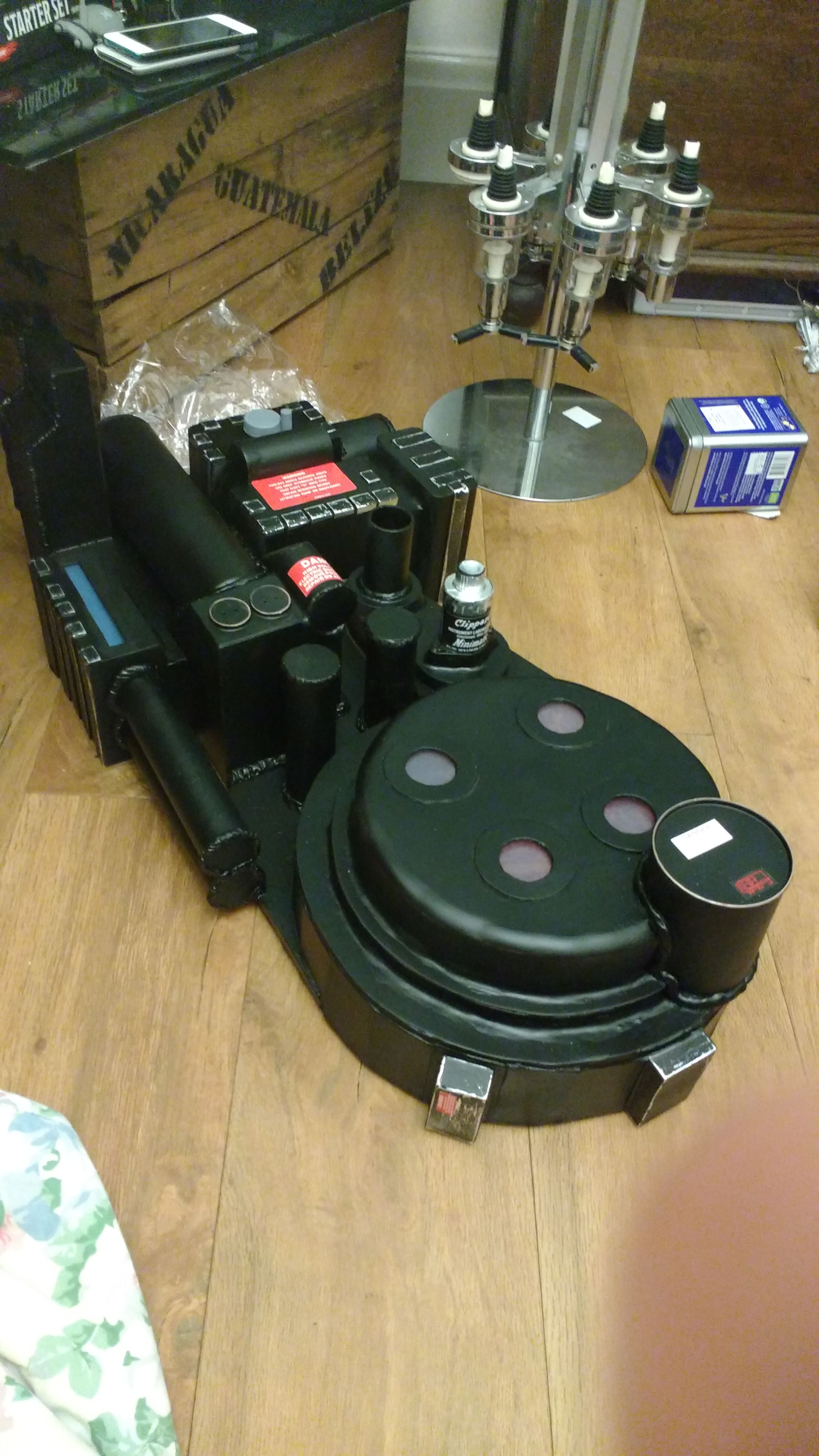
I didn’t want to tackle the bumper or the booster frame so I bought some resin parts along with some cast resistors. The shock mount is the same card tubing as used before covered in strips of card and metal tape. I then sanded for a weathered look and then attached it to the bumper with a metal washer and screw.
After the bumper was drilled and attached I added the wires on the left of the pack. I also took this time to do some weathering with metallic markers.
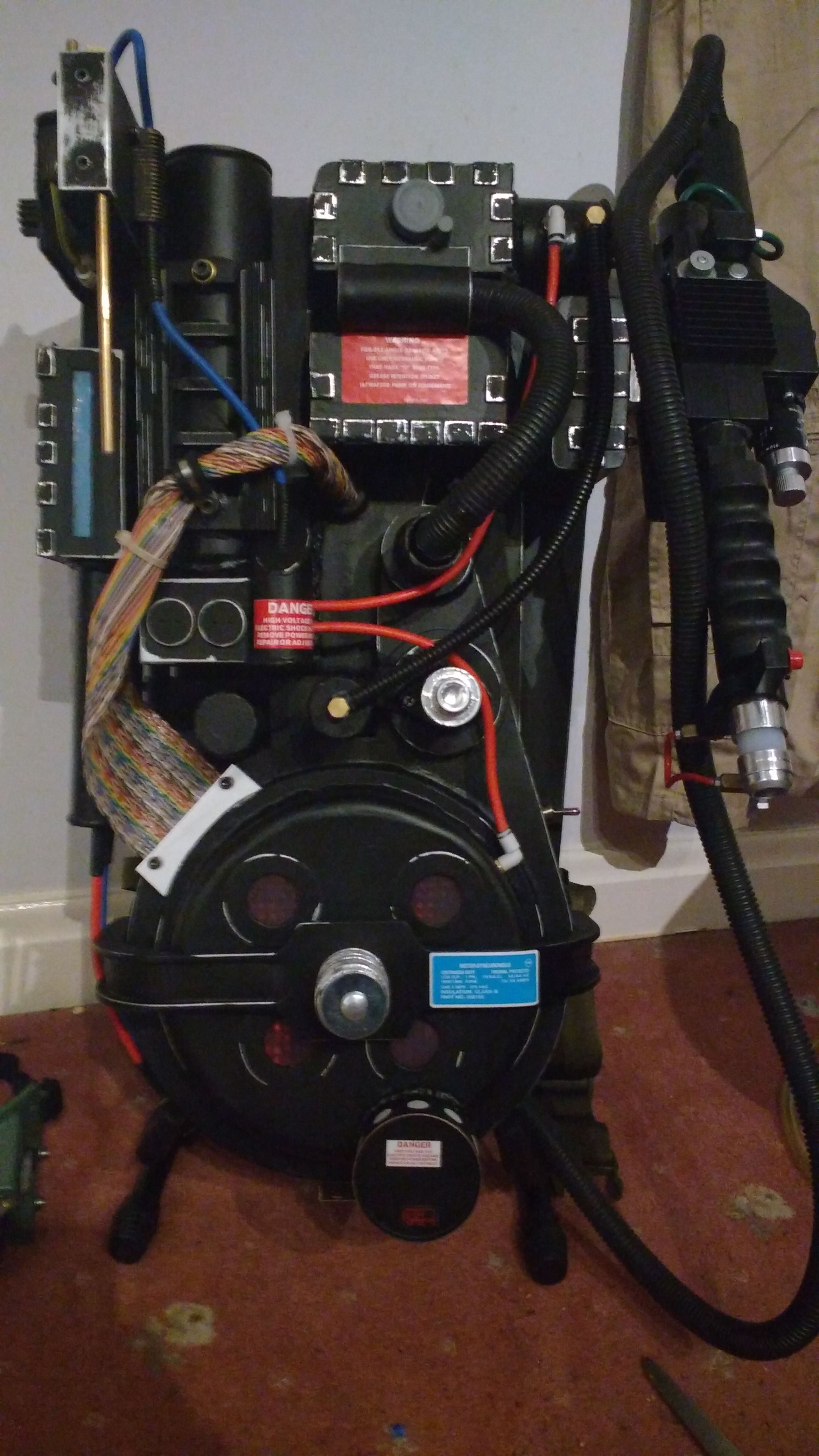
I then received the wand mount, the ribbon cable and the ion arm dowel (thanks to Keymaster props). After adding them and the split loom to the build I attached the main body of the pack to the motherboard.
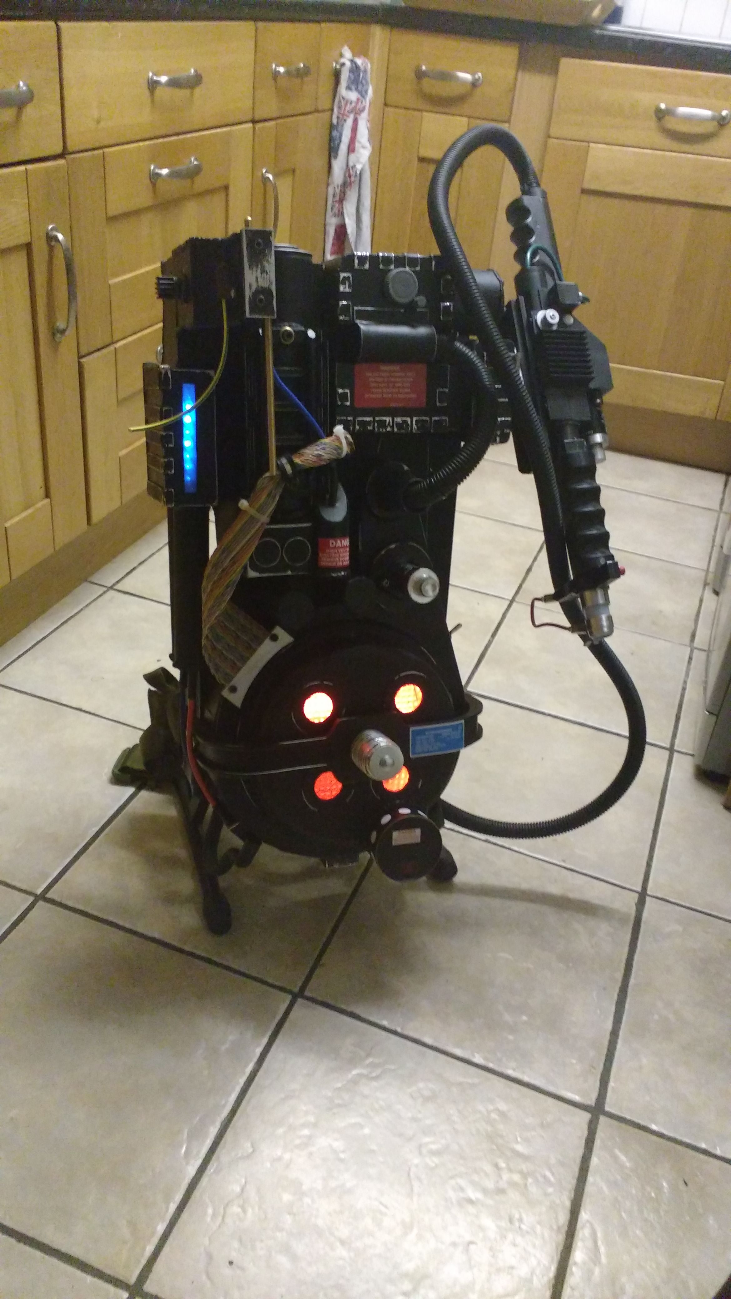
And now the finished product. All wiring complete. I built it in such a way that you don’t need to remove the motherboard to change the batteries. I’m pretty pleased with the finished piece. Overall it took me just over 1 month, waiting for parts to be posted helped to give me time to figure out some issues and fixes particularly with the motherboard.