First of all I have to give credit to Crusader_X… I love his PKE meter designs!!!
I took what I liked about his design and changed it just a little to make my own version of it!!!
I am very proud of it, I think it turned out great!!!
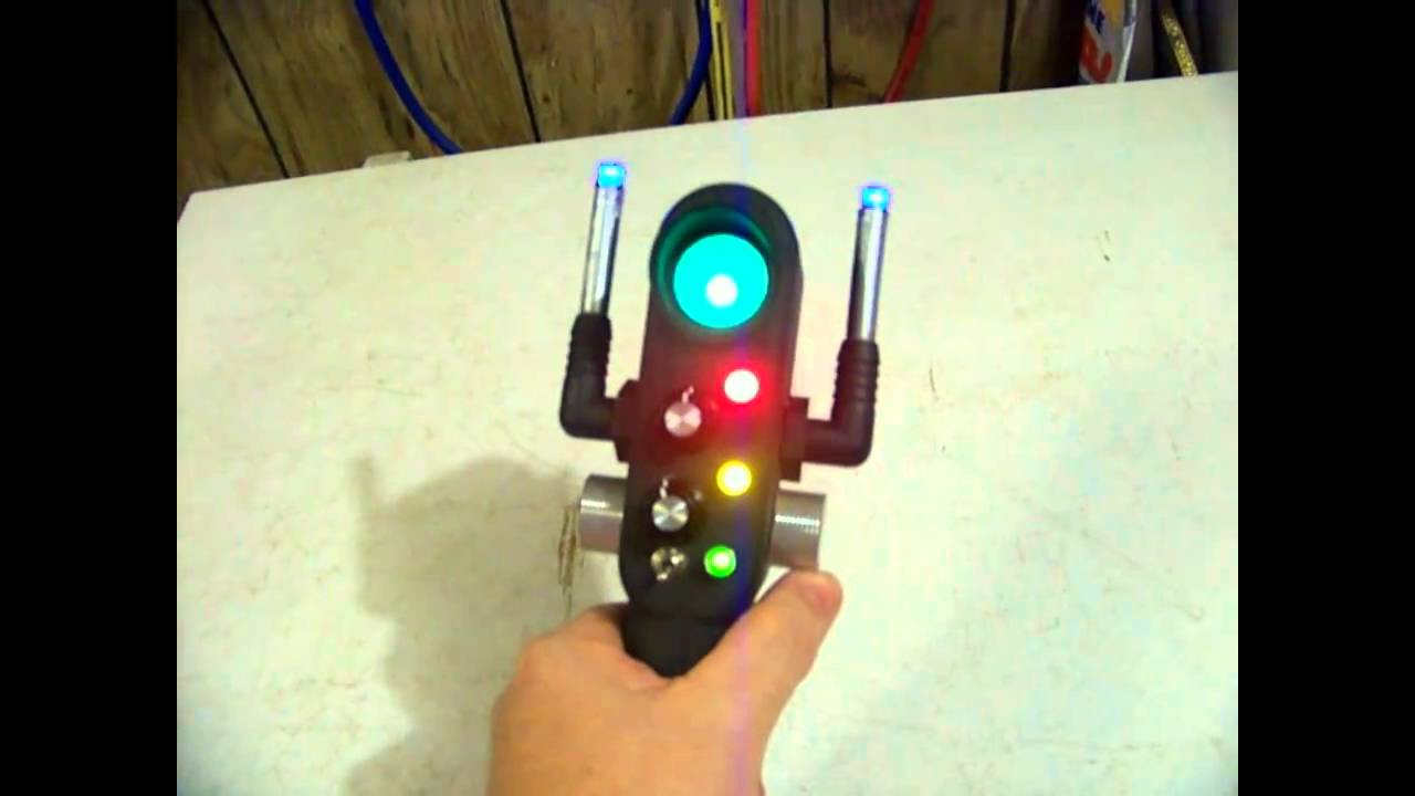
First of all I have to give credit to Crusader_X… I love his PKE meter designs!!!
I took what I liked about his design and changed it just a little to make my own version of it!!!
I am very proud of it, I think it turned out great!!!
That’s superb. Like that!
Nice work!
Wow. I love the light/sound system. It actually gives the knobs a function. How did you mount the light behind the viewscreen if you don’t mind my asking? And do you care to share the electronics diagram for those of us still learning?
Really nice work man!
Yes, I did mount an LED behind the view screen. It is a simple 555 timer type circuit with a potentiometer controlling the speed. I added a small buzzer with the LED’s so it makes a sound with each blink. I am at work now, but as soon as I can… probably in a day or so, I will get the schematic drawn up and put on here for anyone who might want it.
Thanks for all the nice comments! 
Dean,
Any chance of the schematic before Halloween?
Jeff
That’s pretty cool. Nice job!
Sorry, I tried to get it done this last week, but have been working a crazy amount of hours at work. I will do it later today, probably just afternoon sometime!
Well yeah I can see you mounted an LED behind the screen, my question was how? I’m only curious because I have a certain way I mount mine but if you’ve got a different/better way of doing it I’d love to know…

I know the schematic probably could have been done a little more efficiently, but it works! LOL
I put the 2 AAA battery source for the red, yellow and green lights in the handle… the bottom cap is removable to change the batteries. I use a 9V to power the blinking lights. I separated the power source to keep the indicator lights from flickering. The potentiometer is a 50k ohm.
I am pretty new to some of this, but by experimenting with circuit wizard I got it to work.
I hope it helps!
I used a small piece of PVC, about a 1 inch section hot glued behind the screen. Then I used a piece of a circuit board to mount the LED on and hot glued it to the PVC.
It worked out pretty well.
Dean, one thing confuses me about your schematic…what does Switch 1 do? In your video, you only show one switch in use, I assume that’s Switch 2 (the double-pole/double-throw for power). And where is it on the actual PKE?
Switch #1 appears to cut off power to just the buzzer so that you can kill the sound if need be…
That is exactly what the second switch controlled… kills the buzzer sound. I didn’t put in the one that I made, but am thinking about putting it in if I want to silence the PKE meter.
Oh, of course.
“But why wouldn’t you want it to beep all the time?” [SMACK in the back of the head.] “Hey!”
Couple more questions…What parts did you use for the variable resistor and the piezo buzzer? The VR just shows “8%” and there are a lot of piezo buzzers out there.
The variable resistor is actually a 50k potentiometer, the schematic is copied from circuit wizard and that was the position I had it in when I copied, so just disregard the 8% notation.
The buzzer I got from Radio Shack… http://www.radioshack.com/product/index.jsp?productId=2062394