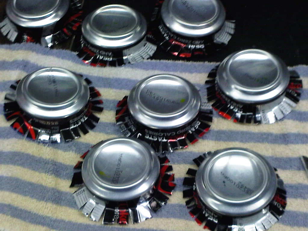
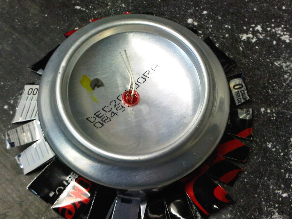
I was thinking about using the bottom of coke cans for the LED housings. The smooth aluminum inside would be a good reflector, and each housing would be sealed to prevent light leaking out from the sides of the clyo.
That instrument bar is huge.
It looks like a deck on the back of a boat.
Yeah, I dropped the ball on it. In any event, the only people who would spot the innaccuracy are people on this forum. I wish the plans were better. They leave the builder to figure out things on their own.
So, I have faced a couple of realities this weekend. I’m not going to finish the pack with lights by the deadline. I will probably be done with the pack, but adding all the gun lights I wanted will have to wait until next year. Thankfully, we will be out of the country for Halloween, so we can get away with wearing these costumes more than once.
If I didn’t have to work this week, I’d be pretty comfortable about finishing, but with the party on the 23rd, I will be lucky if I even get my pack lights working.
Never fear, because I have 4 hours tonight and Friday to finish. Hopefully I can steal a few hours on Tuesday and Wednesday to get some circuits soldered up.
I started Friday with intalling clyo lenses. I had a lot of plastic in case I screwed up.
First, I had to remove the excess glue from around the holes. Once again, this Ebay purchase has cost me time.
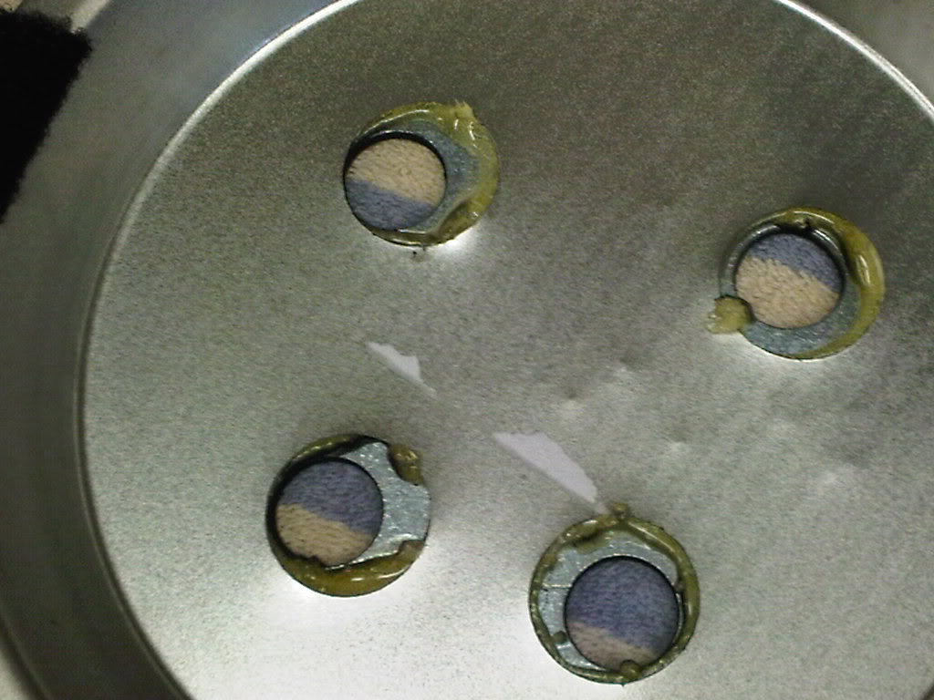
Cleaned up
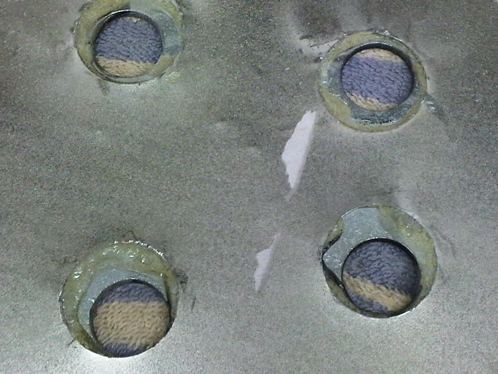
I cut out 1.5" squares and scored one side of the plastic to soften the lights.
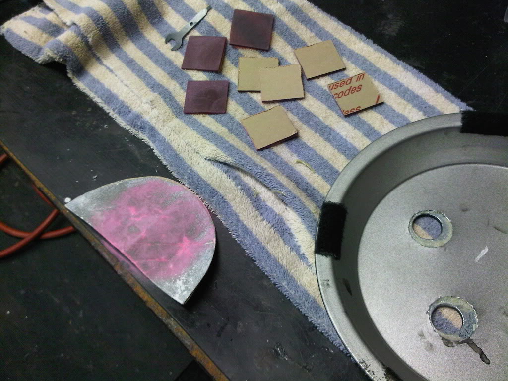
I learned a lesson about Gorilla glue. A little goes a LONG way. I did a Gareee hot glue/Gorilla glue combo. I used too much Gorilla glue, and it expanded to the visible part of the lens. It was a mess. From there, I would just glue down the lens with hot glue, and add little dabs of Gorilla glue to the corners. It worked great.
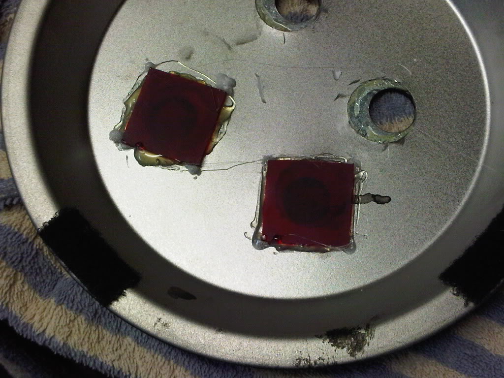
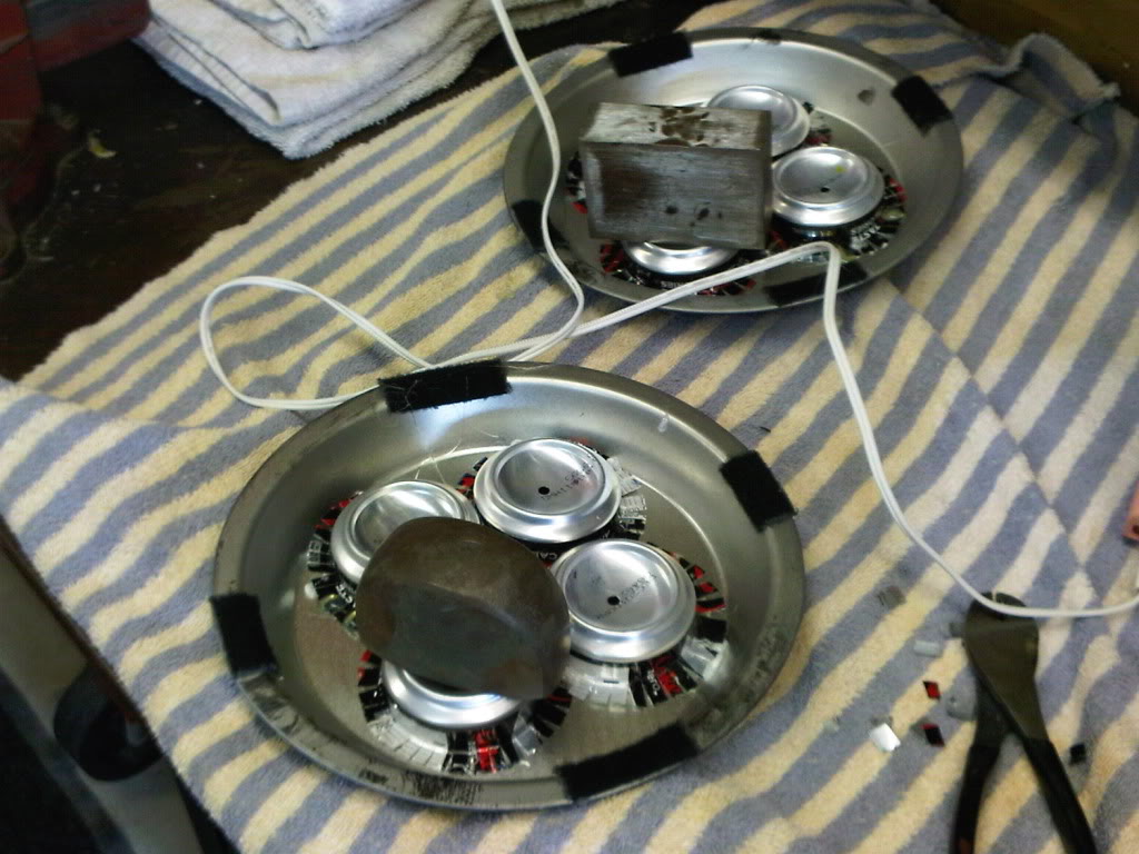
Using large weights to press down the lenses.
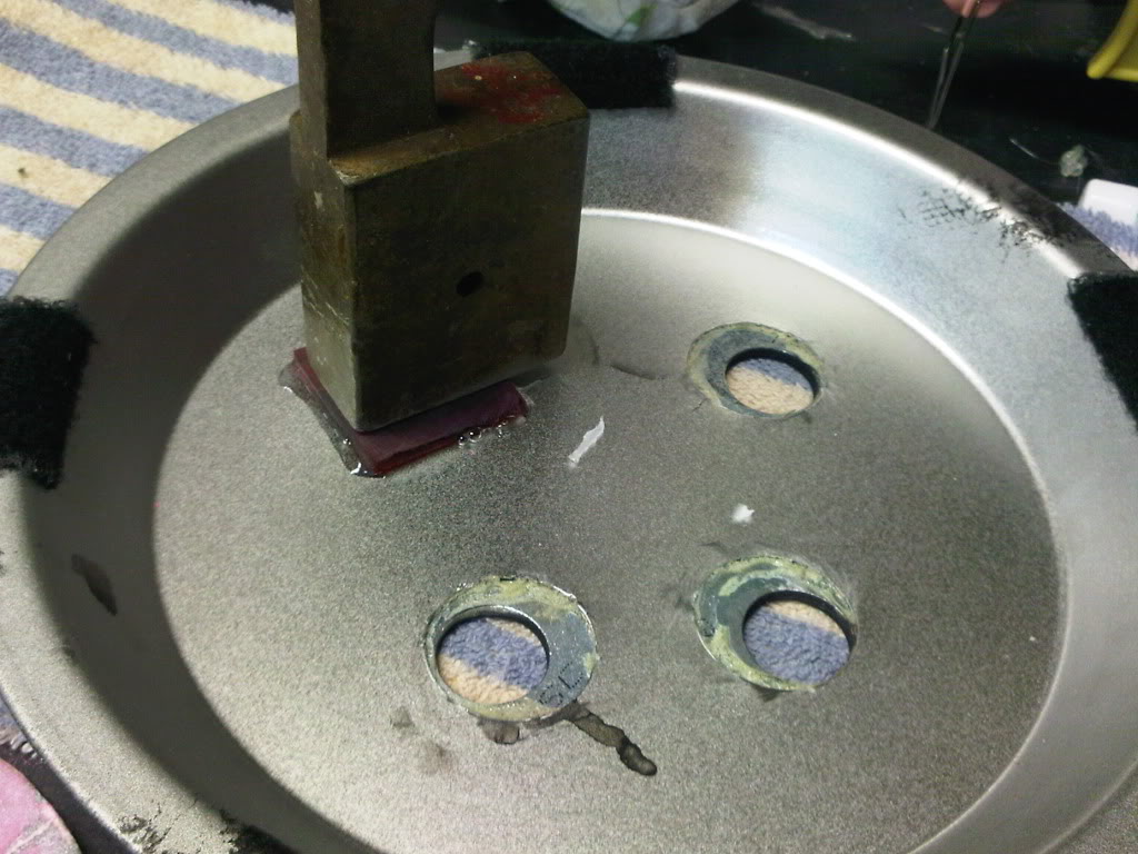
I then focused on the light housings.
Starting with a simple Coke can.
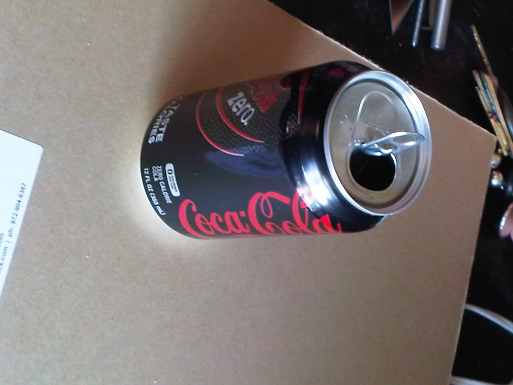
Taped for cutting.
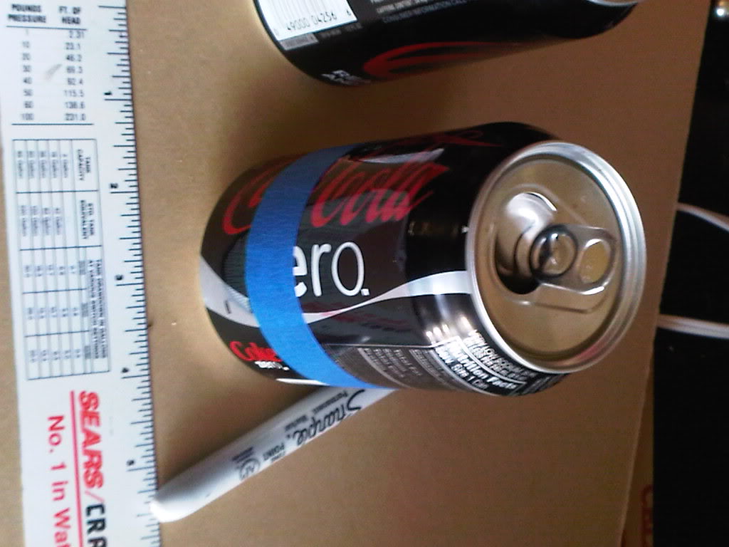
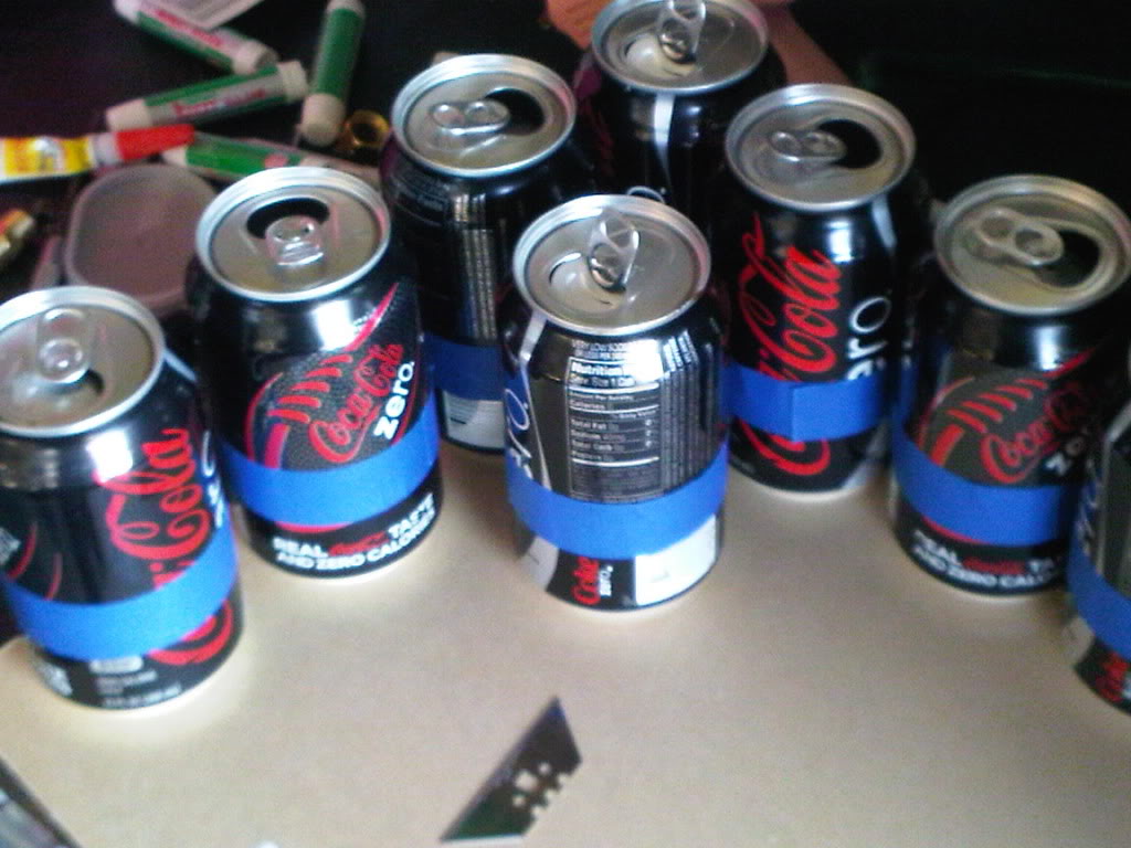
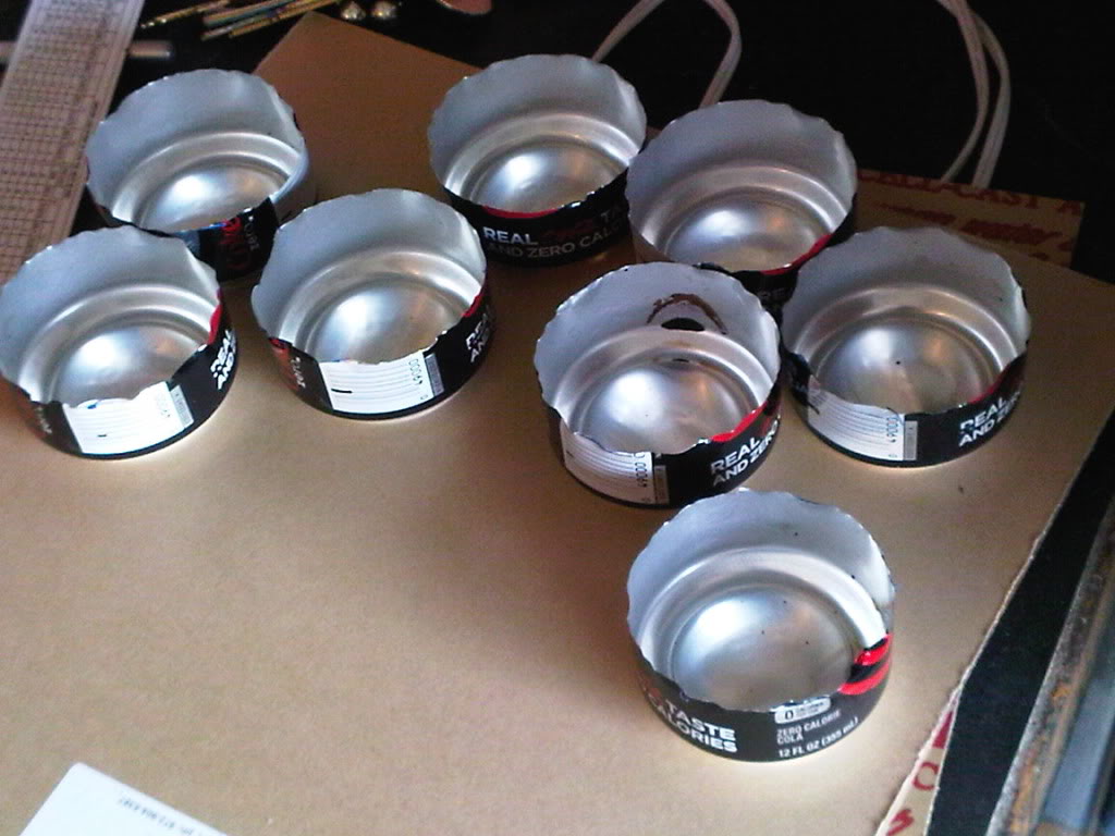
Mounting flanges are cut
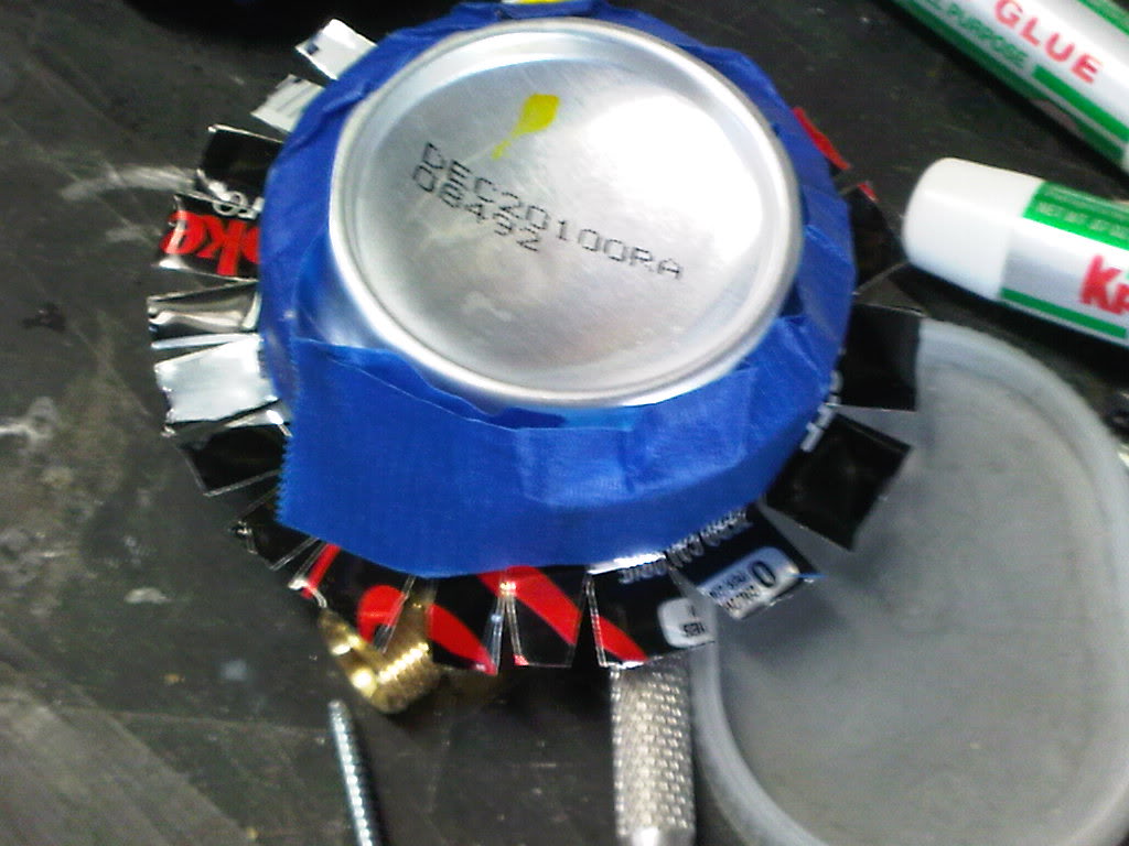
Tape removed.
I drilled a hole where the LED will mount.
I also used weights, Gorilla/hot glue to fasten these to the clyo.
Next, I painted the EDA and booster. I used Gareee’s advice and bought a can of latex flat black paint. I’m glad I did.
Ready for paint.
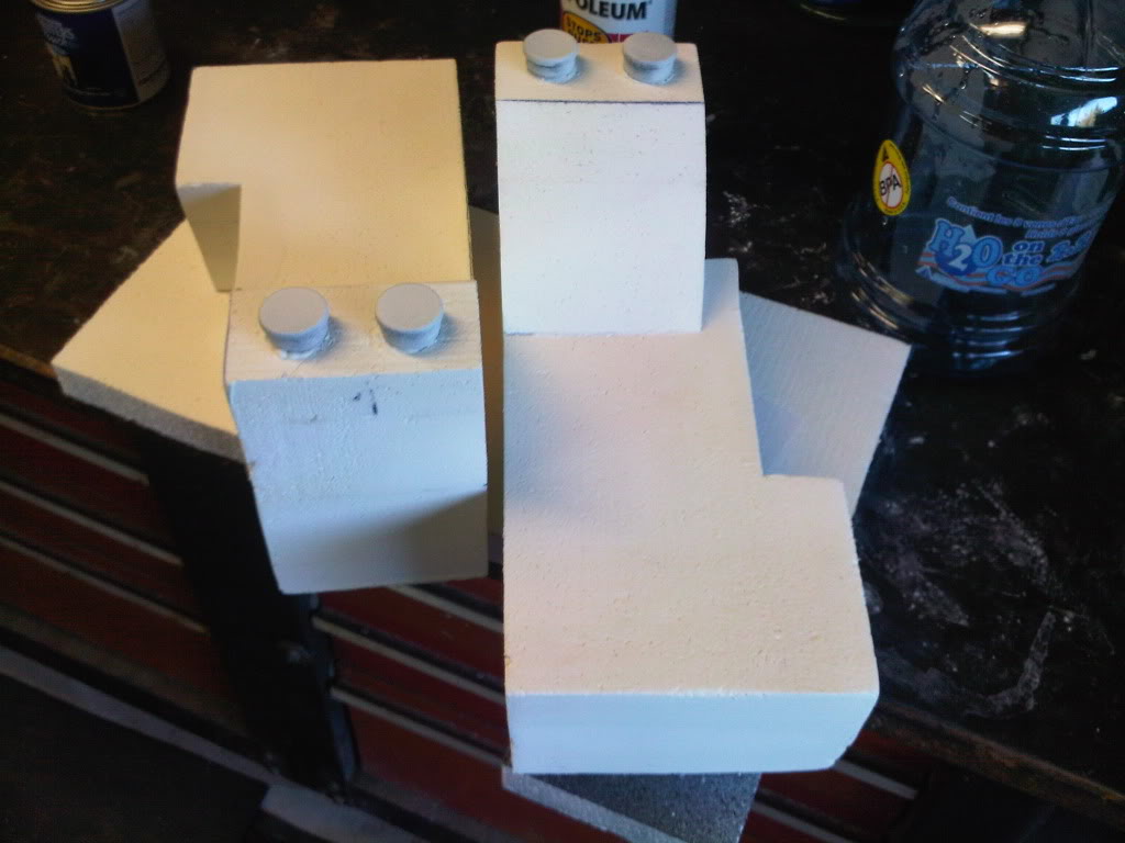
First coat goes on.
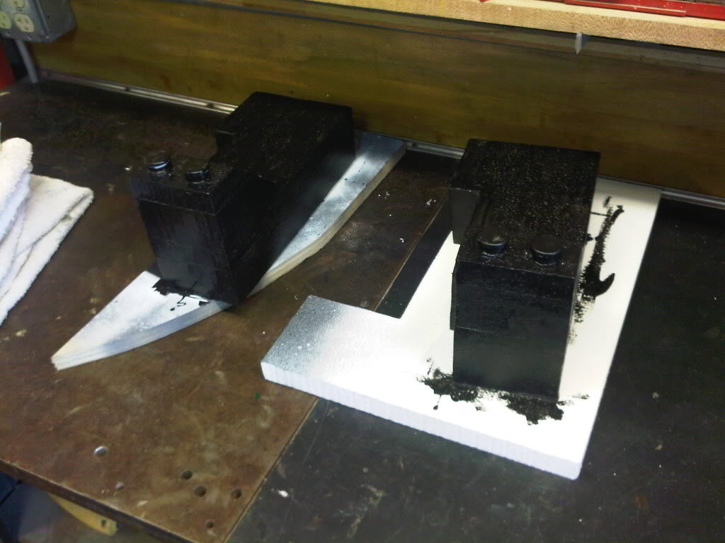
I finished painting the power cell box. It looks nice after some dry brushing, and two coats of flat clear coat.
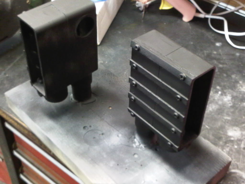
Last week, I started work on the gear/crank box. This weekend, I finished it.
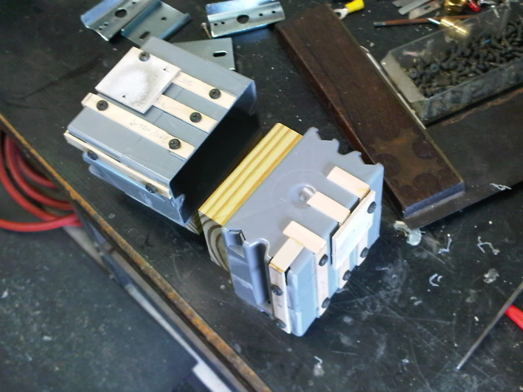
The box after glued wood pieces are affixed to two circuit boxes. I started adding some of the ribs.
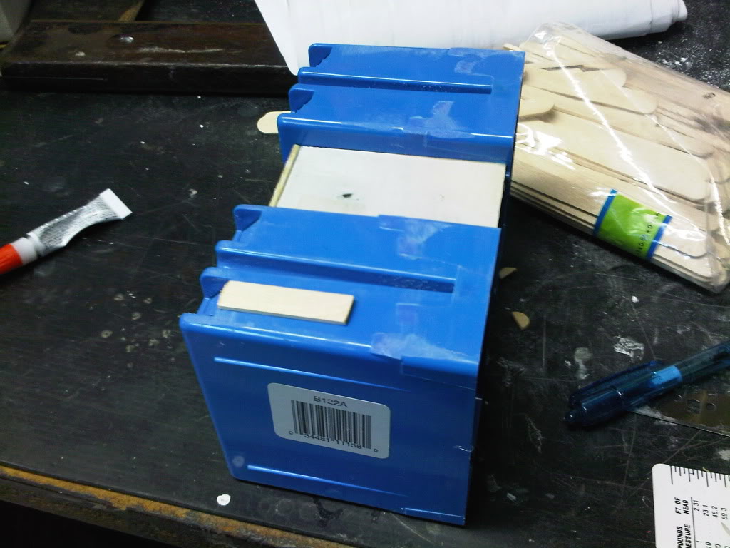
More ribs go on.
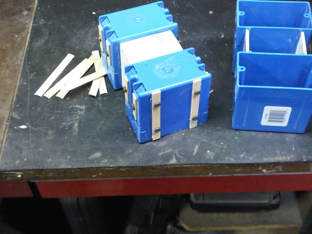
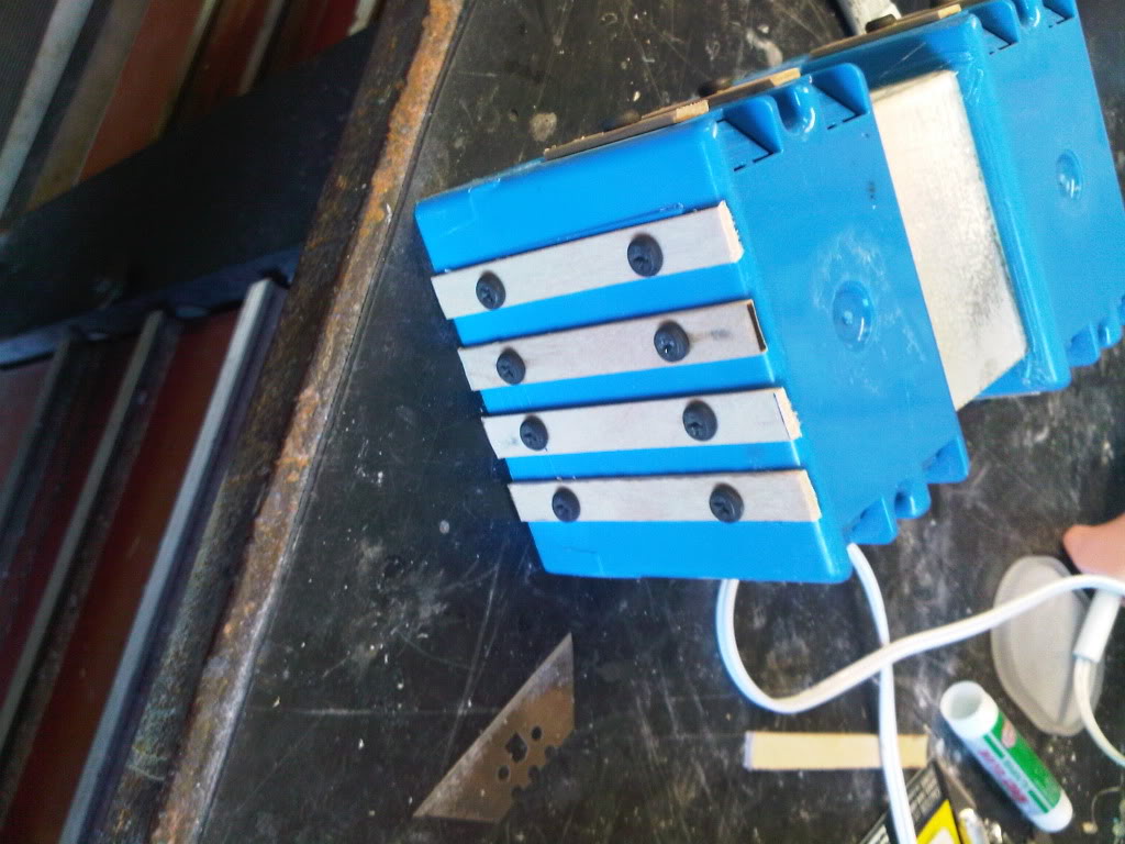
I didn’t have the crank, so I looked around for another idea. I found these pull knobs, and they work for me.
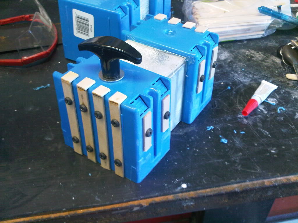
Seeing how the gun block will look next to the gear box.
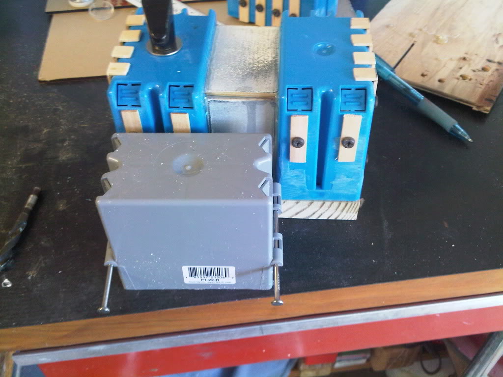
Adding the hose bracket to the gear box.
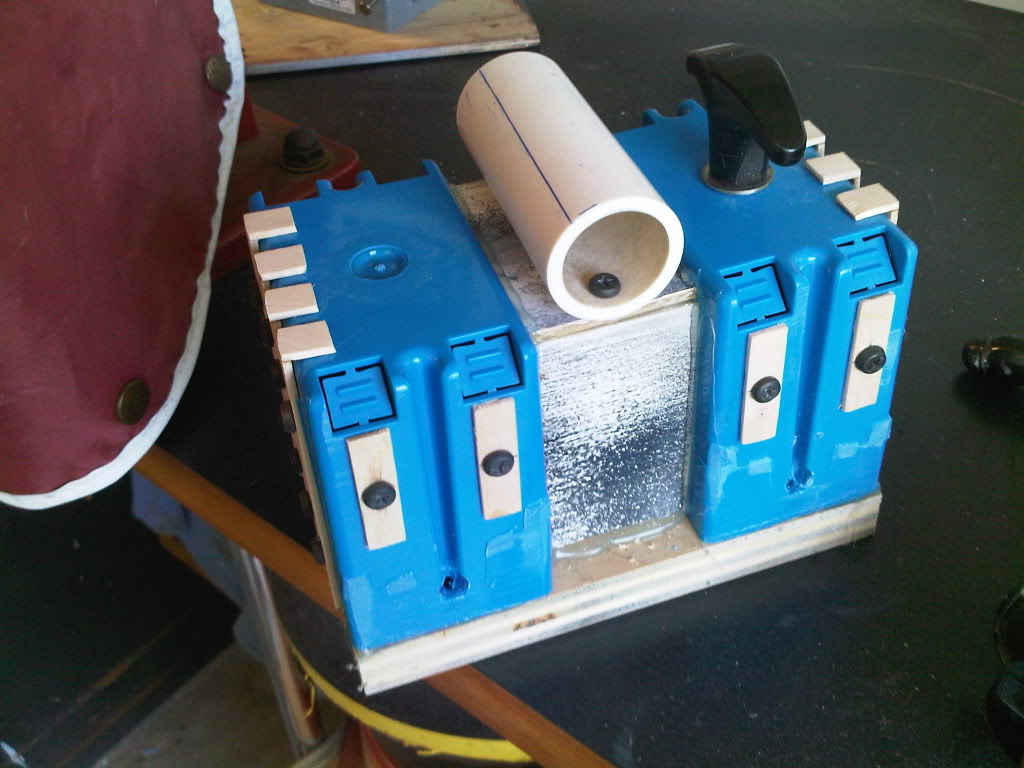
Adding the hose bracket end cap to the gear box.
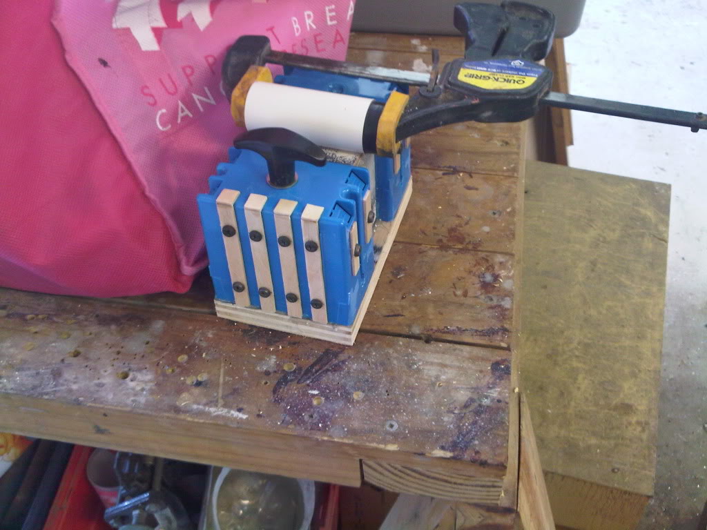
I then started the HGA. Using spray paint caps and some hex screws. To fasten the HGA to the crank box, I cut out a wooden block.

Mounted!
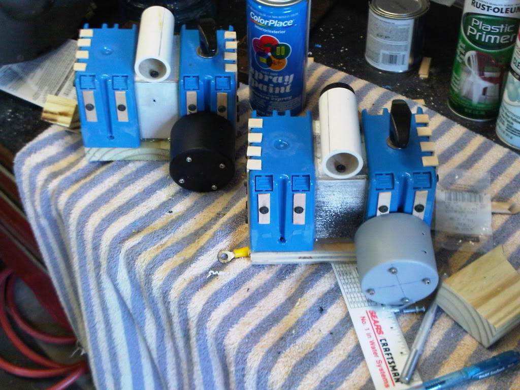
Dry fitting the gear/crank box/HGA assembly.
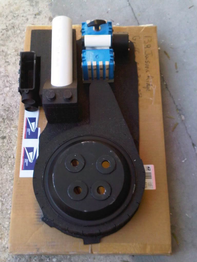
I next turned to finishing the power cell plate. I cut the length of the hole a 1/2" shorter than Otto’s plans, sine I’m not using a full 16 LED setup.
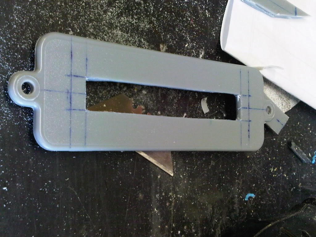
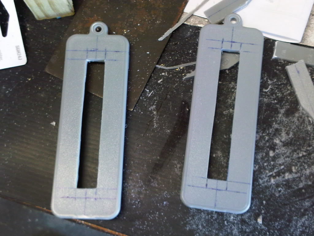
Now, its time for the gun mount.
Sanding down the nail brackets on the boxes.
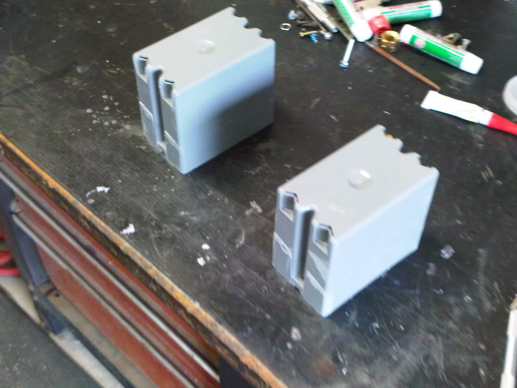
Dry fitting the bridge block and mount box.
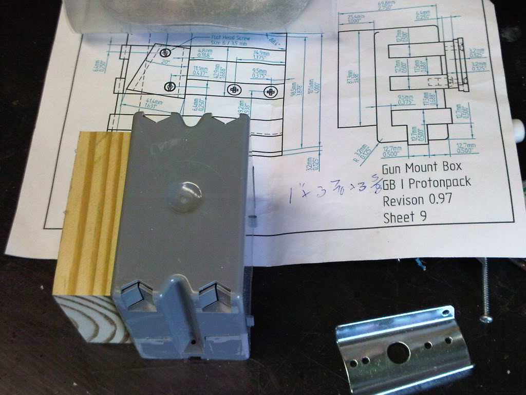
Lining up mount/drilling holes.
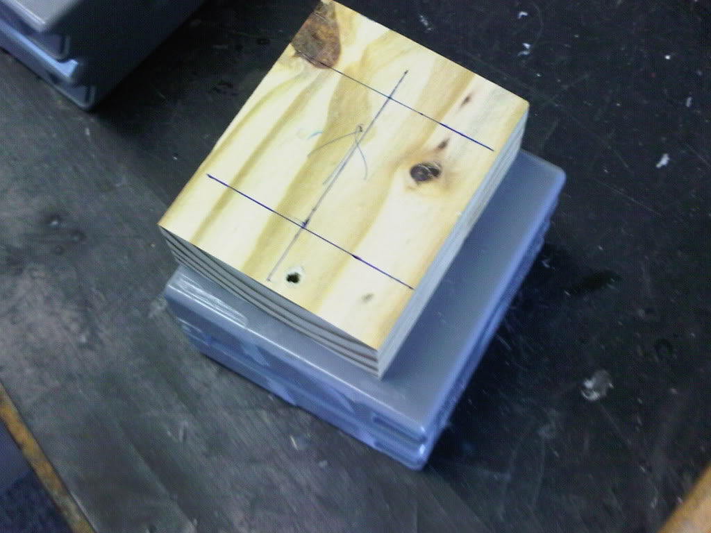
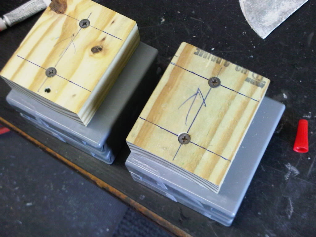
Drilling the mounting screws into the block and mount box.
Adding the ribs to the gun mount box. Yay for popsicle sticks!
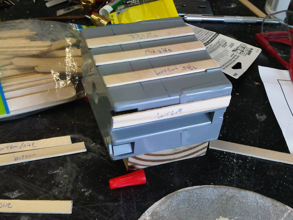
Done with the gun box. Ready for paint!
I also started the louver that goes over the EDA. While not screen accurate, it will pass.
Initial layout.
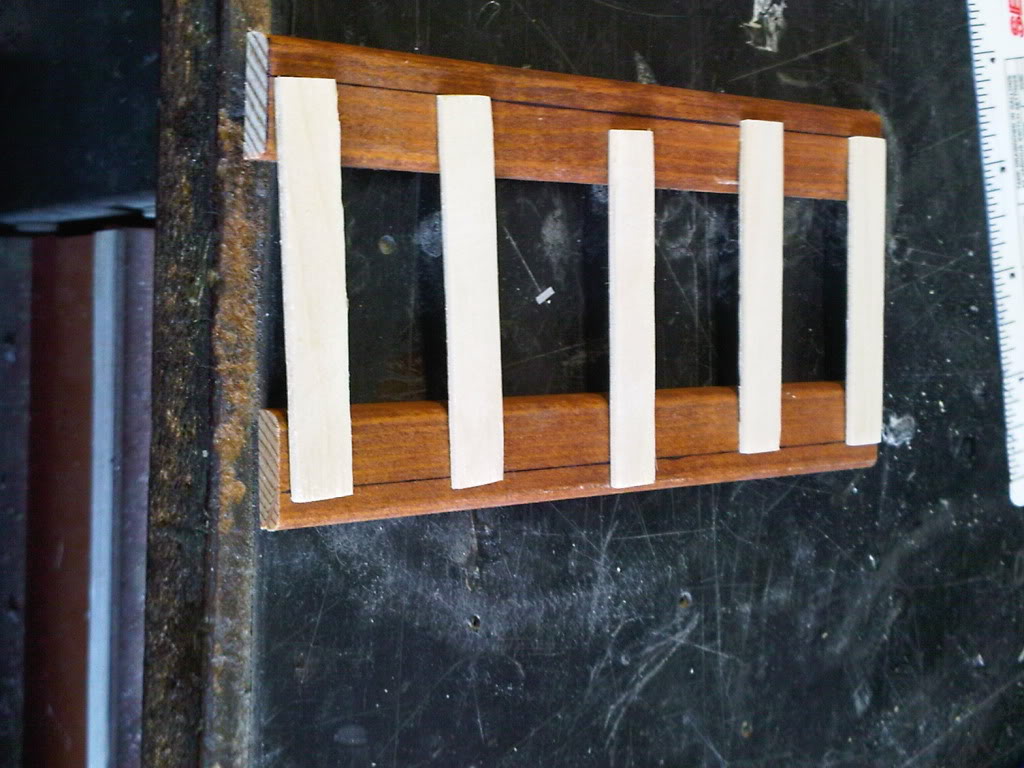
Mounting the pieces.
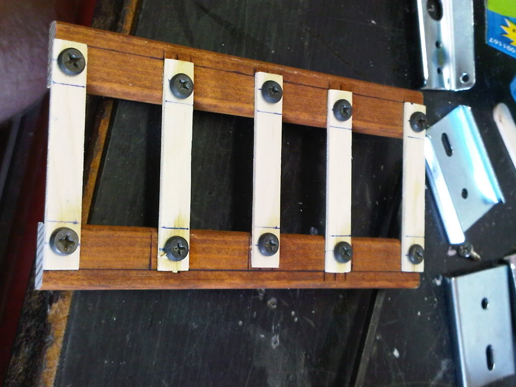
I also added small round dowell to the edges for an extra detail.
I started to rout out the spacer on the pack. This allows me access to the particle thrower hose and circuitry.
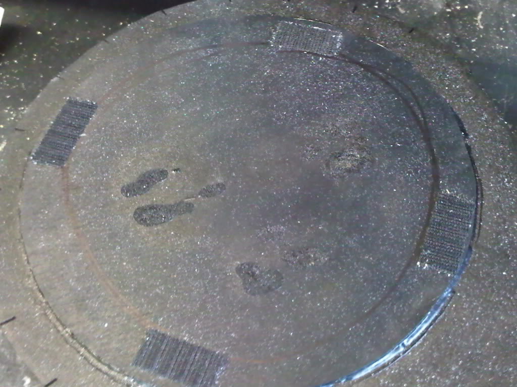
Routed, and the wooden top comes off.
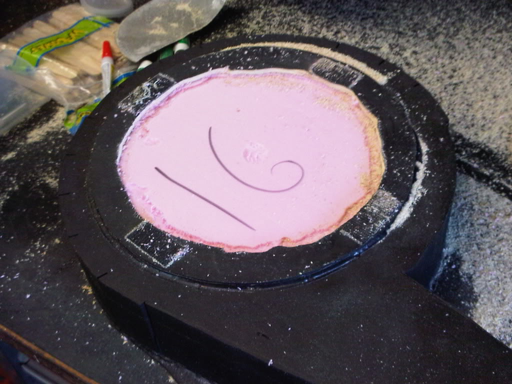
I’m tired. I also started mounting the packs to the frame, and installing particle thrower hoses. This is going to be close.
Excellent documentation! I wish I’d taken more pics when I was building. I really had no idea people would follow what I did years later, trying to duplicate it.
Odds are., someone will like your build, and copycat this a few years from now as well.
Pat yourself on the back, Gareee. If it wasn’t for you, this thread would’ve never existed.
I went home to paint at my lunch break.
My large pieces were done, so I was dying to dryfit them together.

I’m getting excited, now.
After my moment of self-love, I took my pieces out for silver drybrushing and clear coating. I like the dry brushing, because it helps details stick out. Without this, the parts are lost in a sea of black.

With all those screw heads it almost looks a little steam punkish. (Not in a bad way.)
I tried to use flush head screws, but they kept splitting the popsicle sticks. I used these, and they kind of had an industrial look, so I embraced it. Not screen accurate, but I like it.
It makes your pack unique, just like ours are unique. Theree’s something to be said for hell bent accuracy, and also somesthing to be said for creativity as well.
Time flies when you’re under the gun!
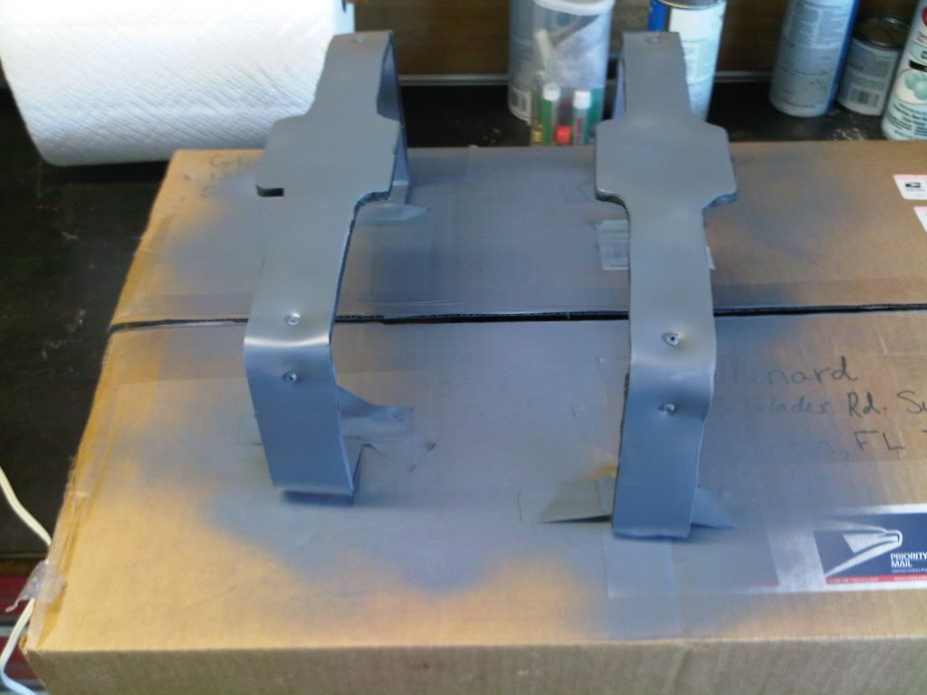
Last night, I completed my bumpers. I was hoping to be on to something else by now, but such is life.
I took a different approach to making the bumpers. I know it may not be accurate, but it’s light, and the sides are flexible to aid in fitting to the pack.
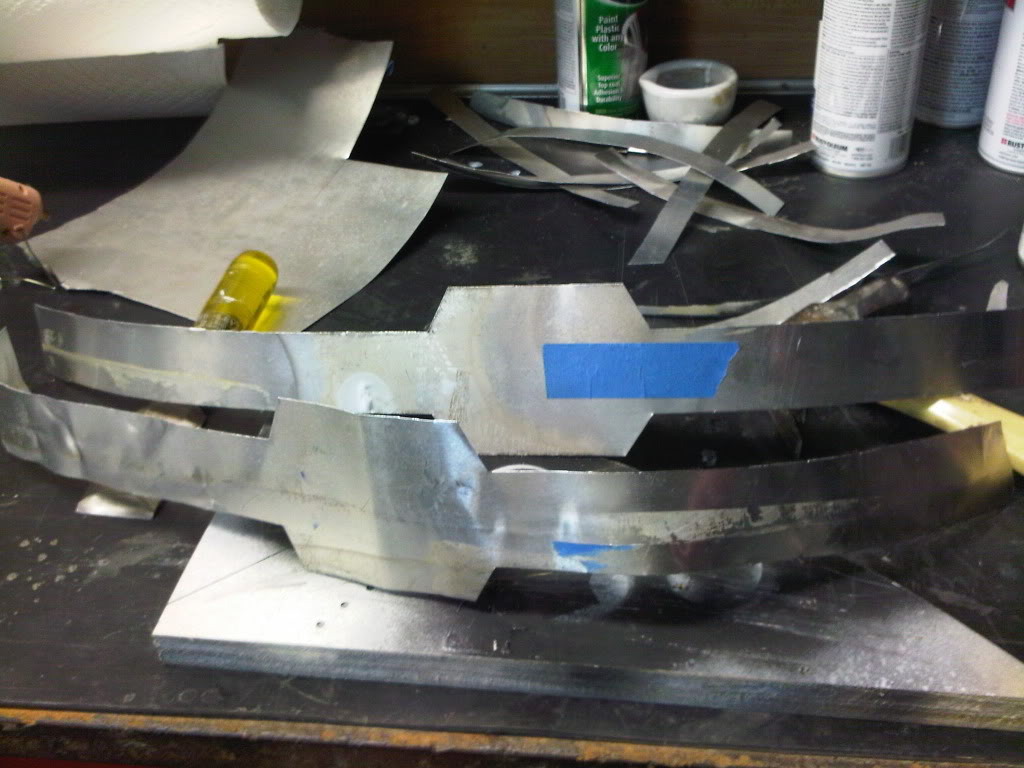
First, I started with the frame of the bumper. This would give the bumper its strength; it would be the “bones” of the bumper.
I used sheet aluminum and cut it into shape via hammer and chisel.
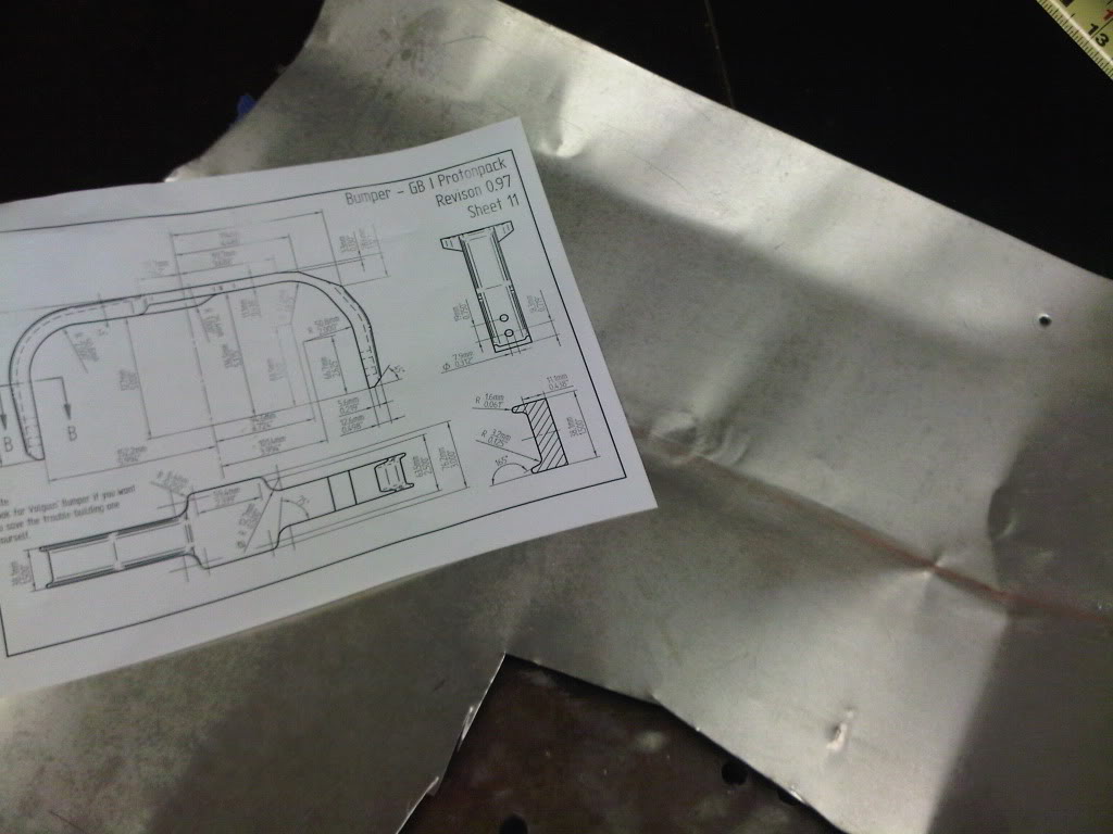
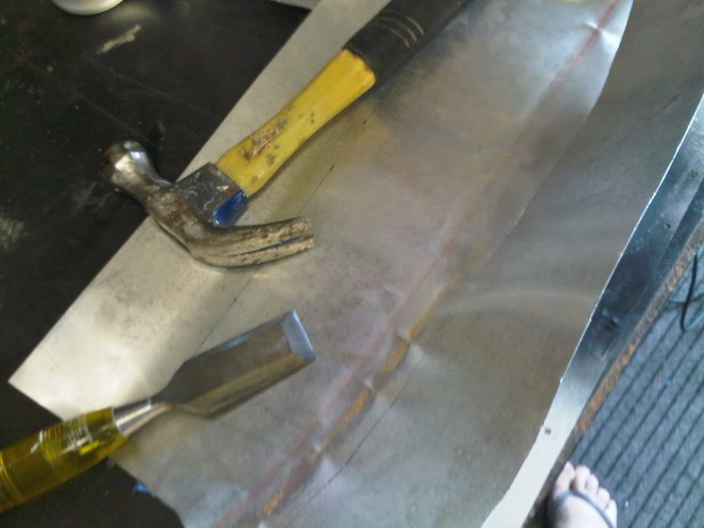
The first strip is cut.
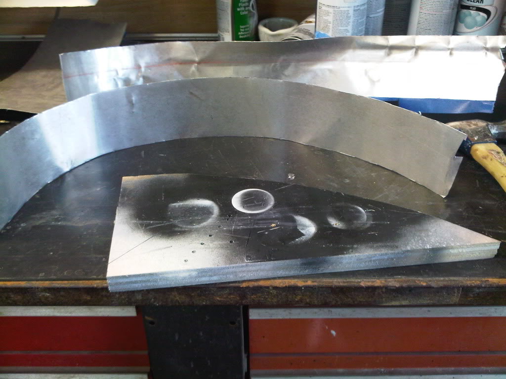
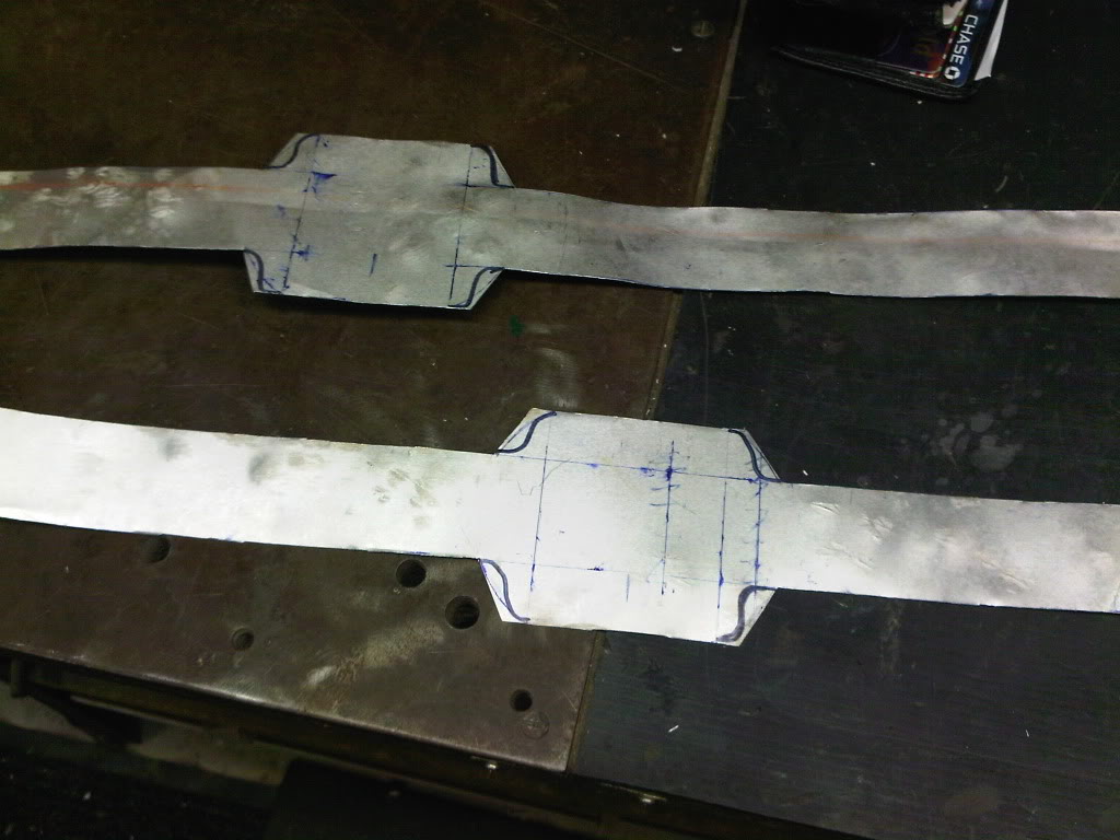
The second strip is cut, and the first strip is cut into the initial shape.

Both initial bumper shapes are cut out.
Some of this aluminum was a bit beat up (It was free, so no complaints here), so I had to flaten it with an autobody hammer and steel block. I didn’t need to get it super smooth, since the cosmetic parts will mount on top of the aluminum frame.
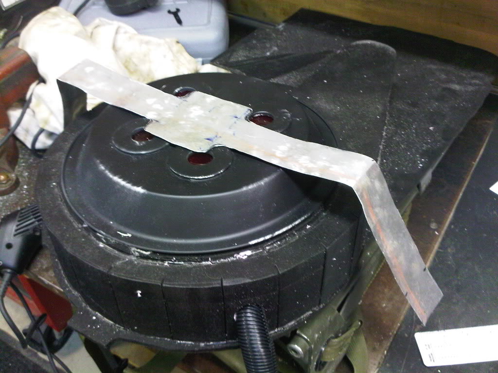
The aluminum strip is test fitted to the pack. I used a dremel to trim the edges of strip.
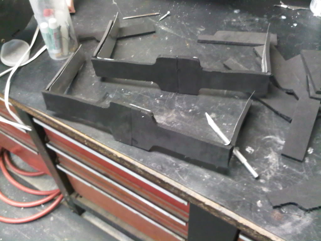
Next up is the foam. This will add body or “thickness” to the frame.
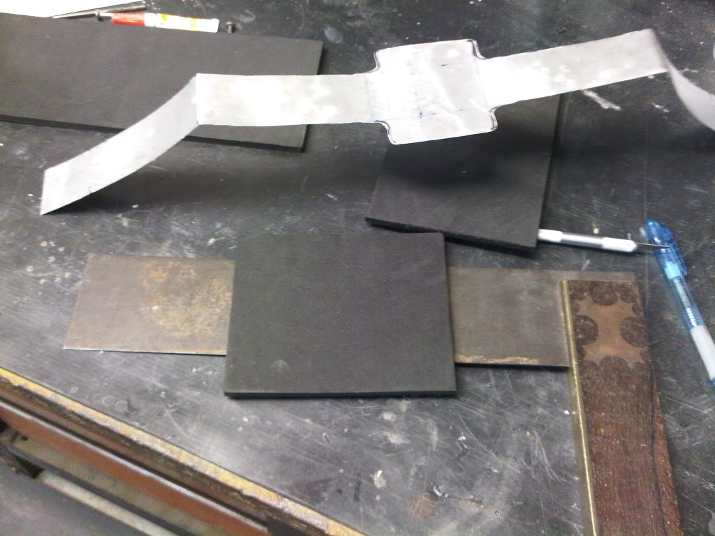
Gluing the foam to the frame.
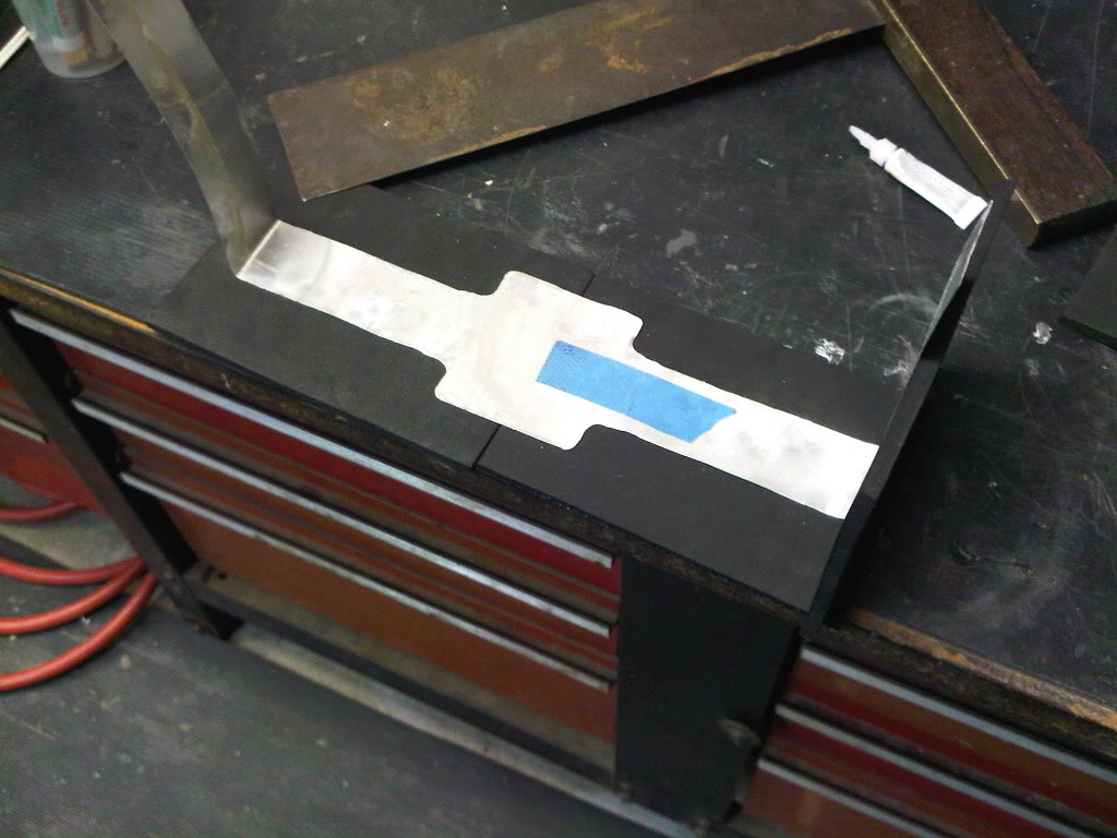
The sides of the frame are glued.
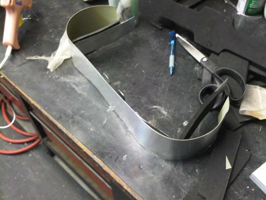
I found this aluminum/plastic sheeting stuff in my dad’s misc. bins of ■■■■. It looks like sheet aluminum from the outside, but it has a plastic backing. This will serve as the “skin” to my bumpers, and will give it that rounded look .
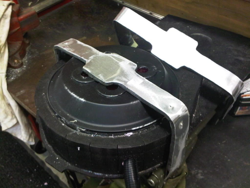
The 4 pop rivets strengthen the corners, and it looks okay. I’m not totally happy with it, but I have no time to experiment.
Today at lunch, I will drill fastening holes, and prime the bumpers. This costume is killing me. Last time I ever build something this complicated.
Nice bumper. I’m the opposite though. I think this is fun as hell and I want to try making a better pack next year, plus a trap and maybe a PKE.
Wish I had a place to hammer out some aluminum like that. ATM, i’m still sans bumper. May try using plastic or wooden rulers like Bradester.
Isn’t Bradester the guy who came up with the plastic sandwich box as a power cell? His builds are pretty freaking awesome.
At lunch, I sprayed my last coat of clear for the pack components, and dryfitted my bumpers. They we’re also primed. They get their color coat tonight.
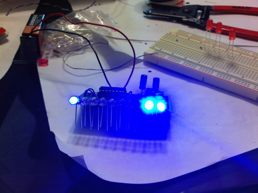
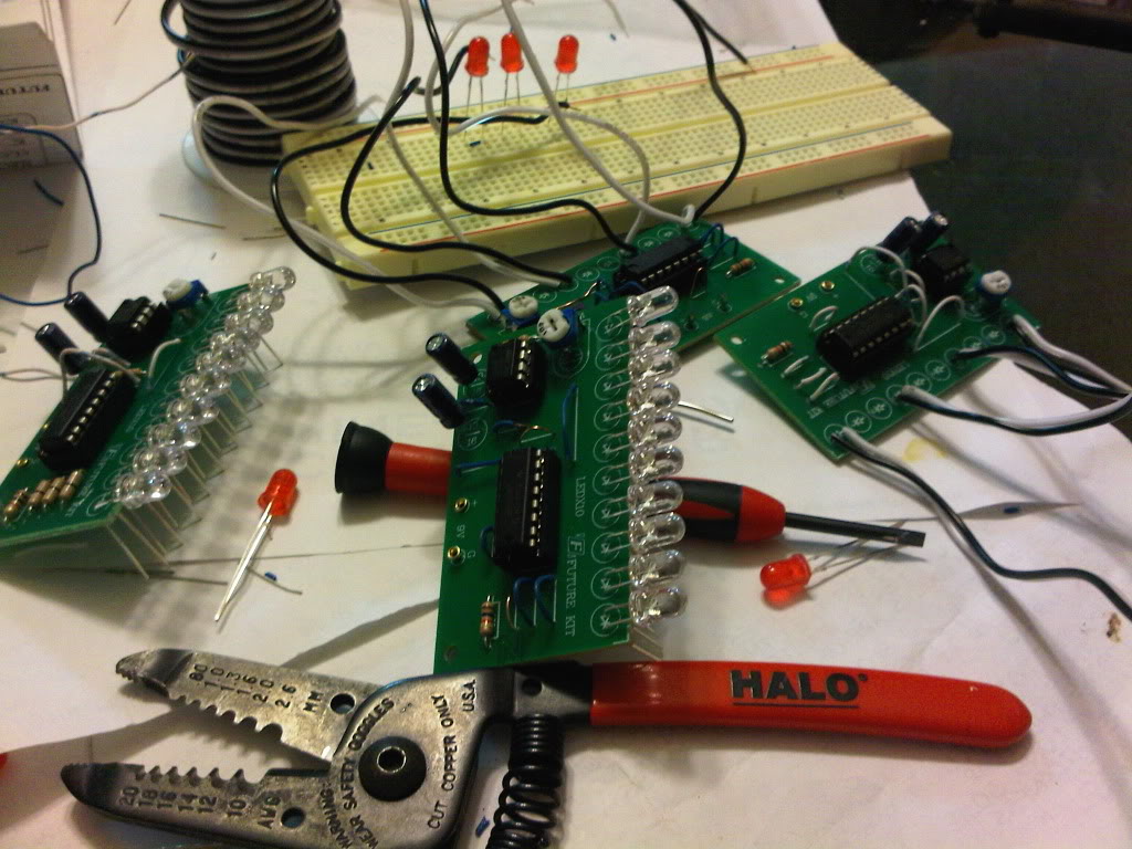
The gods of time smiled upon me yesterday. I was sweating on how to secure enough time to wire up the last clyo and two powercell LED circuits. My dog’s training class was last night, but she has kennel cough (the cold). Because it’s extremely inpolite to bring a sick dog into Petsmart, we just stayed home.
This gave me ample time to wire them up.
The first powercell circuit fires up. Looks pretty!
All the circuits are done! The electronics shop is now closed!
This morning, I did more painting.
The end plate for our ion arms, ion arm hardware, and gun banjos get their first coat of clear.
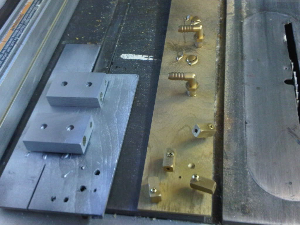
The particle thrower hose ■■■■■■ (The part that attaches to the outside of the pack) gets silver drybrush and its first coat of clear.
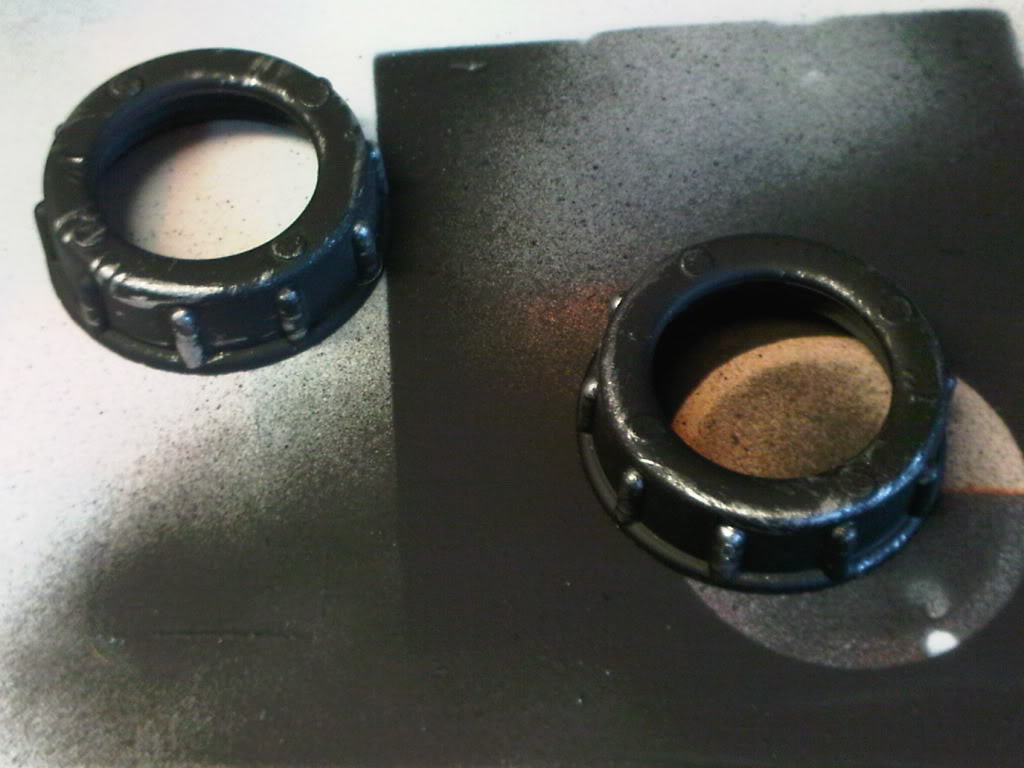
the end caps to the EDA get silver drybrush and the first coat of clear.
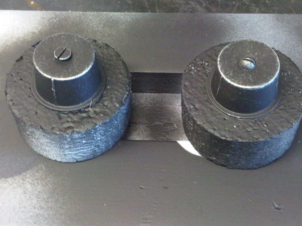
The bumpers get their first color coat.
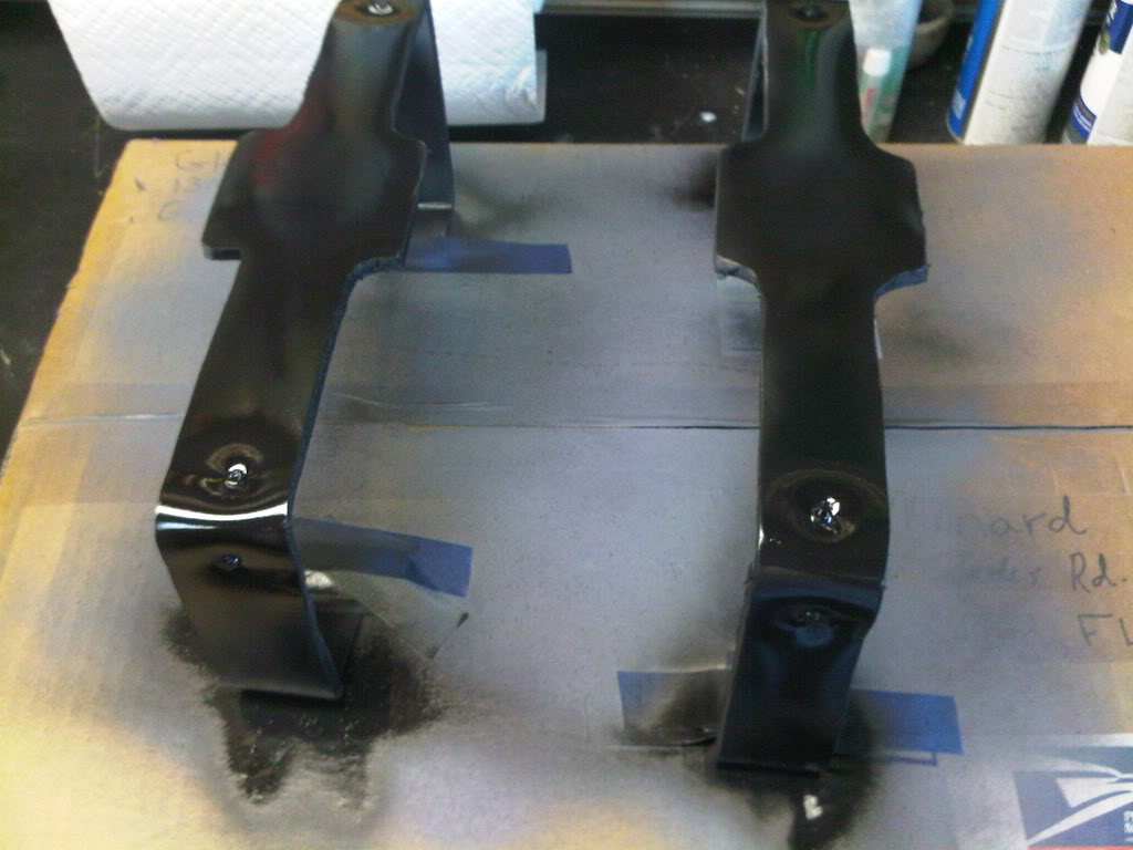
I was thinking of a way to make bumper shock mounts. Paying $20 a piece for “screen accurate” shock mounts is insane, so I had to get creative. Then I saw one of these bottles rolling around on my car’s floor board.
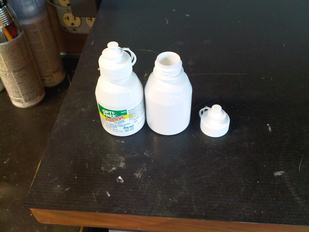
Wheels began to turn, and I started taping away.
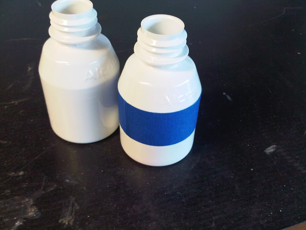
Time to cut off the tops.
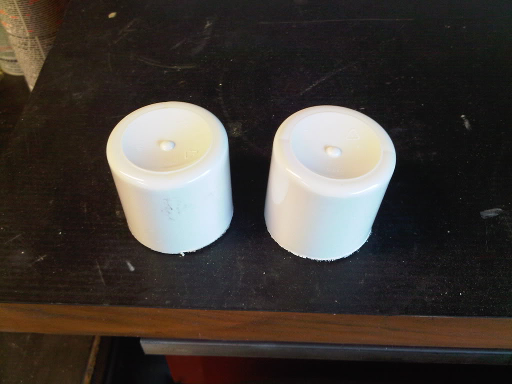
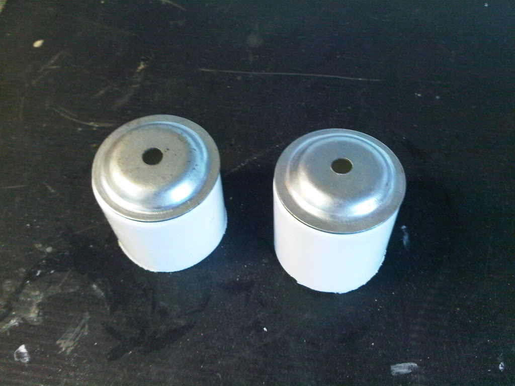
As an added bonus, I found washers that would fit the bill.
However, time was up, and I had to go to work.
More to be posted, later.
Yesterday was a light day. I needed a mental break due to the stress of meeting my Oct 23rd deadline, and my schedule up until that point. Getting the circuits done the previous night allowed me to chill at home. However, I painted before and after work, and during my lunch break.
I was thinking about the bracket that attaches the hose coming from the crank box into the sync generator. I needed a nice ■■■■■■, but I didn’t want to make it out of wood. I dug into my magic bag, and found some rubber furniture feet. They came in a pack of 4, and I used the first two on our leg hose connectors.
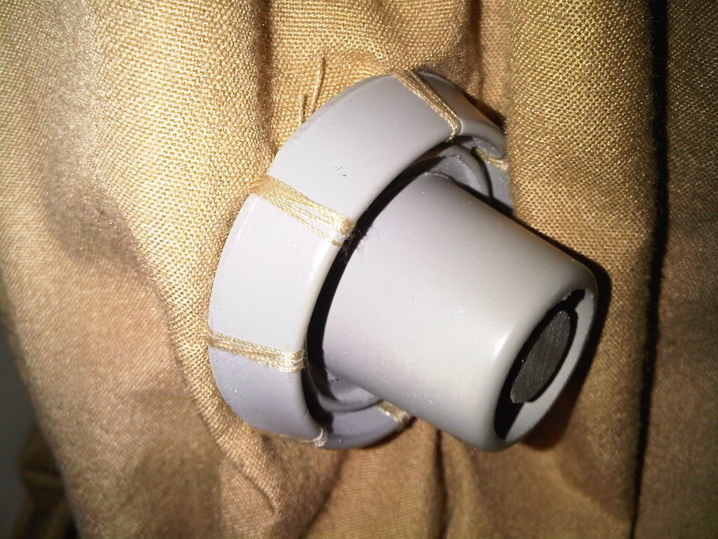
So I pulled them out, and I think they will work.
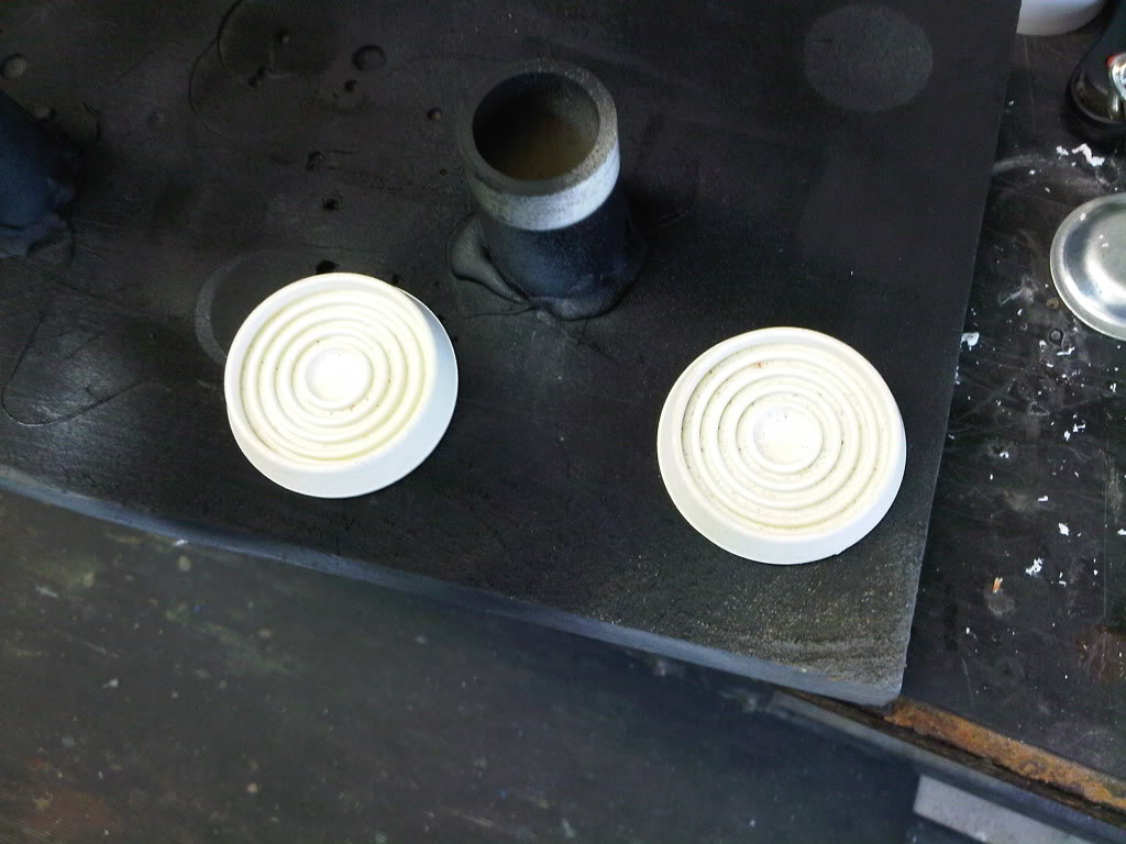
I completed the drilling of the bumper shock mounts. Now they go in for priming.
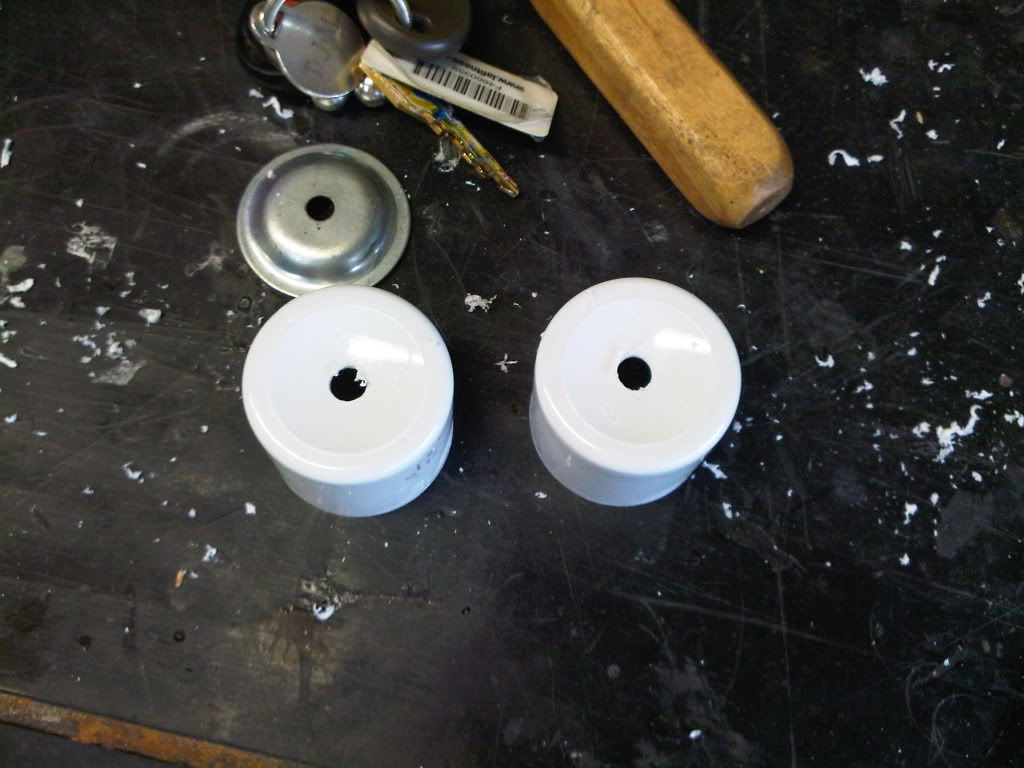
I also gathered small pieces like the little canister that attaches to the side of the EDA. I used 35MM film canisters for this, the pack’s Clippard, and that little pipe that is just below the PPD.
Time for the plastic primer!
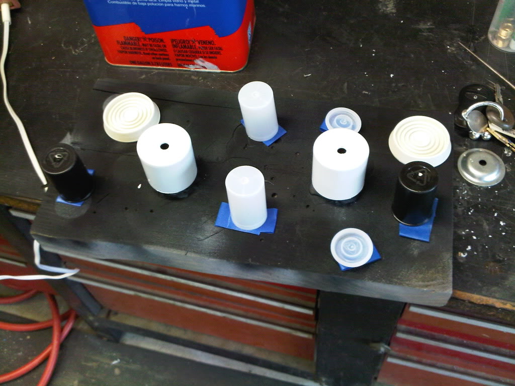
After the first color coat. The power cell injectors, on the right have their silver dry brush and first coat of clear.
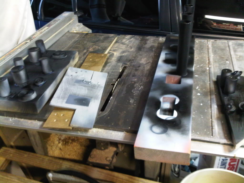
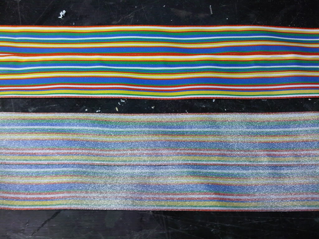
I pulled out my “ribbon cable”. I found this 2.5" wide ribbon at Micheals. I bought like 9 feet of the ■■■■, glued it side by side to widen it to 3.5", and I still thought it looked very gay pride. I wanted to mute the colors and stiffen the ribbon. My solution… A light spraying of silver paint.
Before and after.
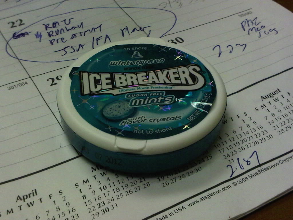
After consulting Otto’s plans, I had to find a properly sized base for the pack clippard. I scoured my local supermarket for a substitute. I thought about peanut butter jar tops, but peanut butter isn’t cheap. At $4.50 a jar, I looked elsewhere. While at the register, I noticed these.
The last component I need are Pringles cans. That’s if I have time.
I grabbed Pringles cans last night. It was hard to dump of all those wonderful chips, but after losing 15 pounds, the last thing I will ever fill up on is crap.
I think the cans are too long. For now, I will paint them, and consult the Otto plans.

These are my clippards. I forgot to add the tips, so they go back to paint. I used a Whiteout cap for one, and glue stick cap for the other.

On another note, the hoses that go from my crank box to sync generator won’t work. The paint is flaking off. No worries. I have more split loom to use.
Tonight is the final build night. I will be working until the wee hours of the morning, but the party is tomorrow, and it must be ready!
I can’t wait to get a decent night’s sleep when this is over. 
Quick lunchtime mockup before returning to work.

How are you making the measurements to cut the pringles can? I have no clue how to properly measure that cylinder against another cylinder…I was bad at math, ok! I spent most of my time watching ghostbusters and other cool movies. 
I think the Otto plans say the N filter is approx 3 5/8". Since the can is longer, I will cut the correct length, and then I will eyeball the cut that joings the N filter to the clyo. The can is made of cardboard, so a hobby knife or scissors will do.
make a paper template of the profile you want to cut, and then just use that on the pringles can, or PVC pipe. I ended up using a abs black plastic pipe, capped it originally with a matching plumbing test cap, but later moved to a more accurate styrene (for sale sign) cap.
The pringles can however does fit inside the abs pipe, so you can spray paint that flat white so it looks like filter material inside the holes.
At this point, I’m figuring out which things I’ll have to live without on my build. The N Filter is at the top of the "left behind’ list.