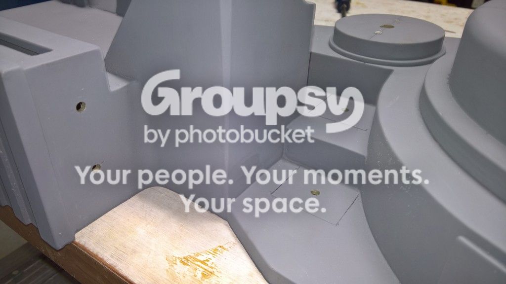
canpara's Semi-Hero GB1 Proton Pack Build (Pic Heavy)

After months of ordering and finding parts and components, I now gathered most of what I need to begin working on my first pack build. I decided to order a Benofkent Props’ kit, which includes nearly everything that one needs to complete a proton pack build (except for any electronics). I have also ordered a number of parts from other suppliers that will either 1) replace some of those found in the kit, 2) supplement the kit build or 3) act as redundant supply.

A very special thanks to benofkentprops, PssdffJay, Jordin, Nicholszz, Naptime, pyhasanon, nstevic01 and Spongeface for supporting me so far with my build!

Please be advised that I fully intend to follow all rules and best practices regarding build threads. If I did something wrong, please let me know as soon as possible and I will take corrective action. :slight_smile:

Now, let’s get to it.

To begin, I have listed my components parts with the sellers name and a link to the item (if possible). Following the list are some pictures of the items:

**Pack **

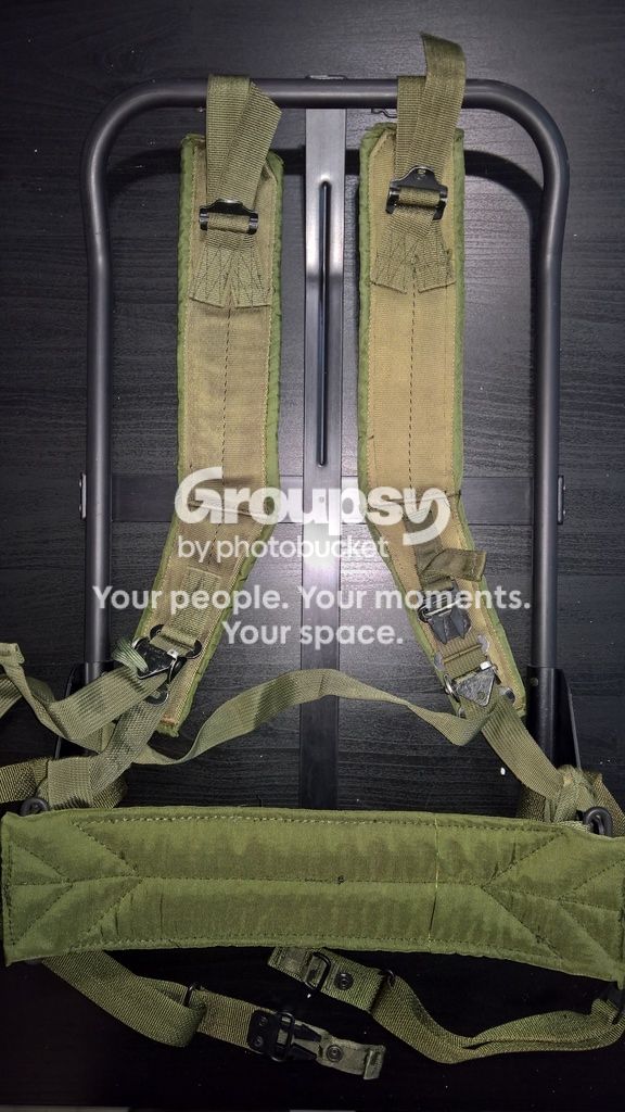
1 x Alice LC-1 pack frame with LC-1 olive drab shoulder straps and LC-1 kidney strap with turnbuckle (fullmetaljacketmilitaria): http://www.ebay.ca/itm/371722723182?_trksid=p2050601.m570.l6004&_trkparms=gh1g%3DI371722723182.N41.S2.R2.TR2

1 x Deluxe Spengler charging plate, blue brick wiring set, auxiliary audio jack and nickel finish XLR jack (nstevic01): FS: XLR "SPENGLER AND VENKMAN" CHARGING PLATE SET WITH PLUGS - For Sale - GBFans.com

1 x Amplified sound board - 2016 revision (GBFans): Pack: Amplified Sound Board - GBFans.com Shop

1 x Powercell and cyclotron light kit (GBFans): Pack: Power Cell and Cyclotron Light Kit - GBFans.com Shop

1 x Powercell and cyclotron ribbon cable connection (GBfans): Electronics: Power Cell / Cyclotron Ribbon Cable Connection - GBFans.com Shop

1 x Cyclotron TVG Color Illumination Kit (Spongeface): INT: CyclotronTVG Color Cyclotron Illumination Kit - For Sale - GBFans.com

1 x GB1 ribbon cable with 1" P-Clamp, alln bolt and two zip ties (neonprops): http://www.ebay.ca/itm/291717578292?euid=eddc512118c2442c970a103085c36543&bu=43090668480&cp=1&sojTags=bu=bu

1 x Ribbon cable aluminum hold down (GBFans): Pack: Ribbon Cable Aluminum Hold Down - GBFans.com Shop

1 x Ribbon cable clamp – 1.25 inch (GBFans): Pack: Ribbon Cable Clamp - GBFans.com Shop

1 x Metal bellows (GBFans): Pack: Metal Bellows - GBFans.com Shop

1 x Clippard R-331 (GBFans): Pack: Clippard R-331 - GBFans.com Shop

1 x Dale RH-25 Resistor (Naptime)

1 x Dale RH-50 Resistor (Naptime)

1 x Dale PH-25 (Dreamstalker)

2 x Legris straight fitting replicas (GBfans): Pack: Mack's Factory Legris Straight Fitting Replica - GBFans.com Shop

3 x SMC 4 mm elbow fitting (GBFans): SMC 4mm Elbow Fitting - GBFans.com Shop

5 x Clippard hose barb (GBFans): Pack: Clippard Hose Barb - GBFans.com Shop

3 x Clippard brass elbow (GBFans): Pack: Clippard Brass Elbow - GBFans.com Shop

1 x Clippard brass elbow for GB1 ion arm: Pack: Clippard Brass Elbow (GB1 Ion Arm) - GBFans.com Shop

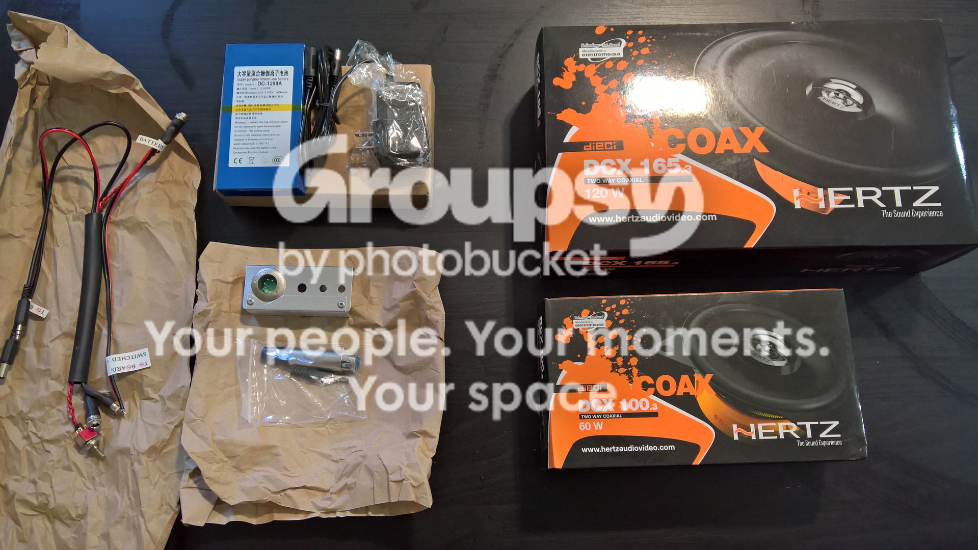
1 x 12V 9800 mAh (Blue Brick) Battery: https://www.amazon.com/gp/product/B00R3VDL46?psc=1&tag=gbfans-discourse-20

1 x 6.5" 4 ohm speaker - Dieci DCX 165.3 120W by Hertz (Visions Electronics): http://www.hertzaudiovideo.com/car-audio-coaxials-dieci-dcx165_3/

1 x 4" 4 ohm speaker - Dieci DCX 100.3 60W by Hertz (Visions Electronics): http://www.hertzaudiovideo.com/car-audio-coaxials-dieci-dcx130_3/

4 x Reflectors: http://www.digikey.ca/product-search/en?keywords=A108489-ND

3 x In Glas Co hockey pucks (Pro Hockey Life): https://www.prohockeylife.com/hockey-accessories/other-accessories/inglasco-practice-hockey-puck

Neutrino wand/particle thrower

[list]1 x Proton gun body

1 x Proton gun pop mech kit (including spring and elastic bands)

1 x Heat sink

1 x Lever

4 x Gun knobs

1 x Trigger instrument bar

1 x Rear cylinder

2 x Side discs (GB1-style no knurl)

1 x Front cylinder

2 x Brass spacers

1 x Clear tube

1 x Trigger tip

1 x Gun track

1 x Gun track disc

1 x S-hook

1 x S-hook disc

1 x GB1 v-hook

1 x Egon disc

All screws included

1 x Proton gun/wand light kit (GBFans): Pack: Proton Wand Light Kit - GBFans.com Shop

1 x Proton gun/wand ribbon cable connection: Electronics: Proton Wand Ribbon Cable Connection - GBFans.com Shop

1 x Wand lights bar graph bezel, wand tip LED and white strobe LED (Spongeface): FS: Wand Lights Bar Graph Bezel, WandTip LEDs, White Strobe - For Sale - GBFans.com

1 x Clippard R-701 (GBfans): Pack: Clippard R-701 - GBFans.com Shop

2 x Legris banjo fitting replicas (GBFans): http://www.gbfans.com/shop/legris-banjo-fitting/[/list]

Bolts and screws

• Note: A US Imperial to SI measurements Conversation Table (for bolts and screws) is useful for reference purposes: https://www.boltdepot.com/fastener-information/US-Metric-Conversion-Table.aspx

  • Black ridged cap style bolts: (Edmonton Nut & Bolt): http://www.edmnut.com/
    [list]4 x M3 10 mm (resistor screws)

3 x M4 10 mm (gun disc + trigger box)

8 x M4 16 mm (gun base + trigger)

2 x M4 40 mm (gun track)

6 x M5 30 mm (ribbon + ladder + clippard)

1 x M5 80 mm (HGA)

Shell ABD bumper bolts (Lowes):

  • 4 x M6 30 mm

Shell mounting bolts to the motherboard (Lowes):

  • 4 x M6 30 mm

Main parts screws: (Edmonton Nut & Bolt): http://www.edmnut.com/

  • 6 x M5.5 75 mm (3/16" x 3") self-drilling roof screws with rubber washer (2 for injectors, 2 for beam line and filter, 2 for ion arm)

Shock mount bolt (Edmonton Nut & Bolt): http://www.edmnut.com/

  • 1 x (1/4"-20 x 2") bolt

PPD mounting screws (D&D Bolt Supply):

  • 2 x (10 x 3/4") self-drilling screws

Mounting hardware for aluminum motherboard to the ALICE frame pack (Canadian Tire):

  • 3 x 2" 1/4-20 round head Philips bolts/screws

5 x 5/8" OD, 1/4" IO washers

3 x 1/4" wingnuts[/list]

Components that I am looking to purchase

1 x MS91528-3S2G Crank Knob

Parts that were purchased, but will not likely be used

  • Certain resin parts from Benofkent Props kit

1 x Full GB1 Neutrino Wand Kit, including metal v-hook (Benofkent Props): https://www.facebook.com/groups/364457410396568/

1 x Alice LC-1 pack frame with LC-2 olive drab shoulder straps and LC-3 kidney strap (GBFans): Pack: ALICE Pack Frame (Imported) - GBFans.com Shop

1 x Cyclrotron booster LEDs kit for GBFans pack lights (Spongeface): FS: Wand Lights Bar Graph Bezel, WandTip LEDs, White Strobe - For Sale - GBFans.com

1 x Ghostbusters 2 Ribbon Cable (GBFans): Pack: Ghostbusters 2 Ribbon Cable - GBFans.com Shop

4 x Red cyclotron lenses (GBFans): Pack: Cyclotron Lens - GBFans.com Shop

4 x Reflectors: http://ca.lightmalls.com/smo-reflector-for-c8-xm-l-t6-2pcs

Paints and adhesives

Dupli-color automotive primer series adhesion promoter – Clear (Canadian Tire): http://www.canadiantire.ca/en/pdp/dupli-color-adhesion-promoter-for-plastic-flexible-surfaces-0476558p.html

Dupli-color metalcast anodized surface color spray – Red (Canadian Tire): http://www.canadiantire.ca/en/pdp/dupli-color-metalcast-paint-311g-0477445p.html

LePage Super Glue Ultra Gel Control (Home Depot): https://www.homedepot.ca/en/home/p.lepagesupsup-super-glue-ultra-gel-control.1000658943.html

Rusto-oleum Painter’s Touch Ultra Cover 2X Coverage Primer – Grey (Home Depot): Spray Primer | Rust-Oleum 2X Ultra Cover

Rust-oleum universal paint & primer in one – Satin Black (Home Depot): Universal | Enamel Paint & Primer Spray Paint | Rust-Oleum

Photos

  • Benofkent Props Proton Pack Kit
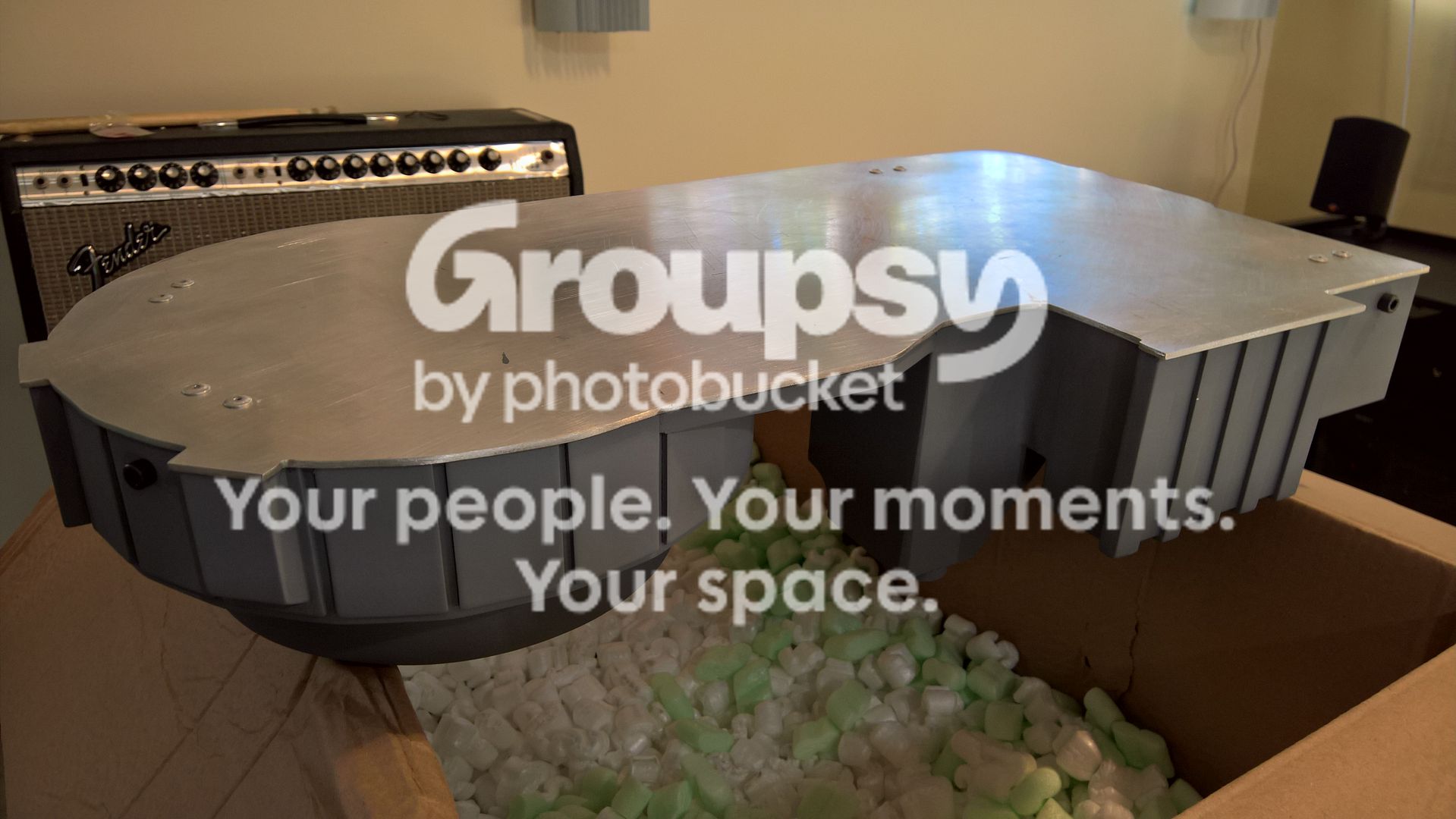
    [list]Polyurethane Shell Mark 2:
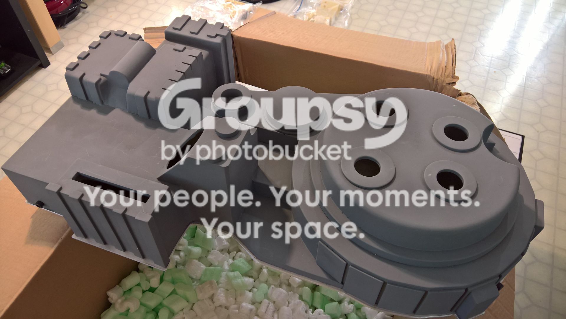
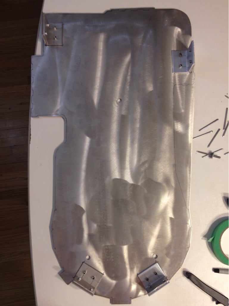
Pre-mounted aluminum motherboard:
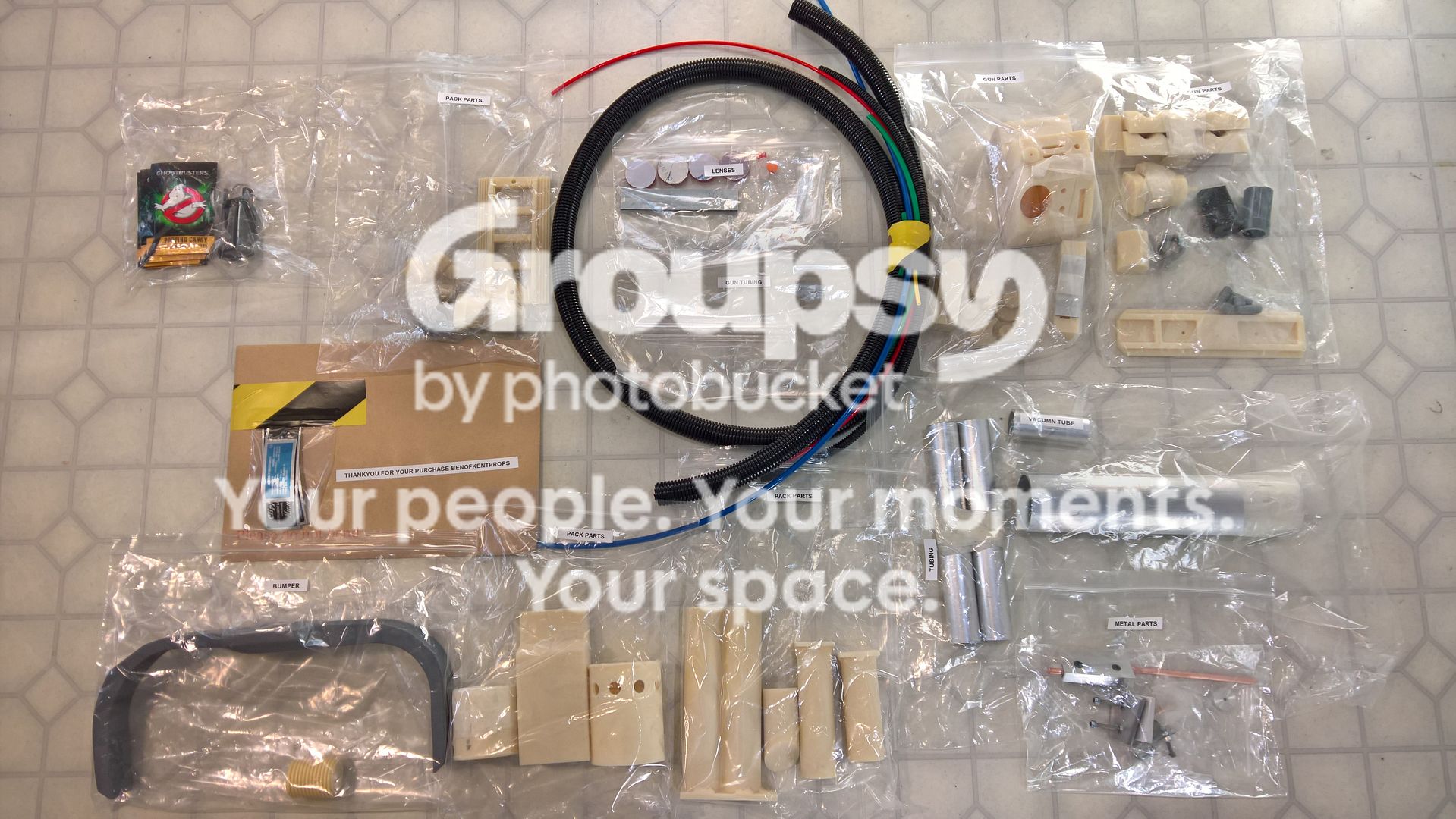
Other parts included in the kit:
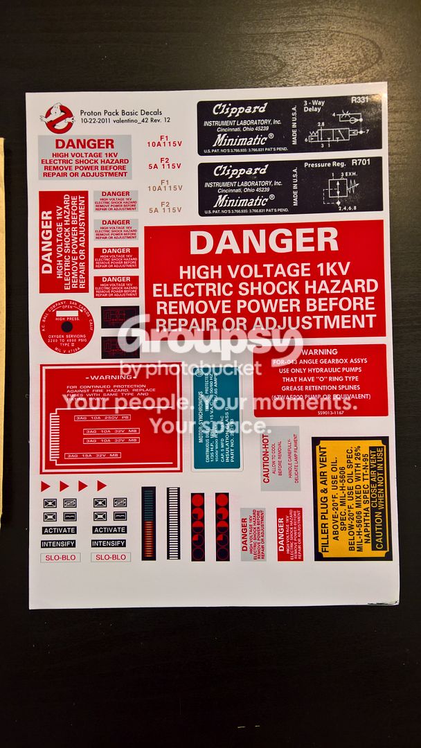
Vinyl Labels found in the manila envelope:
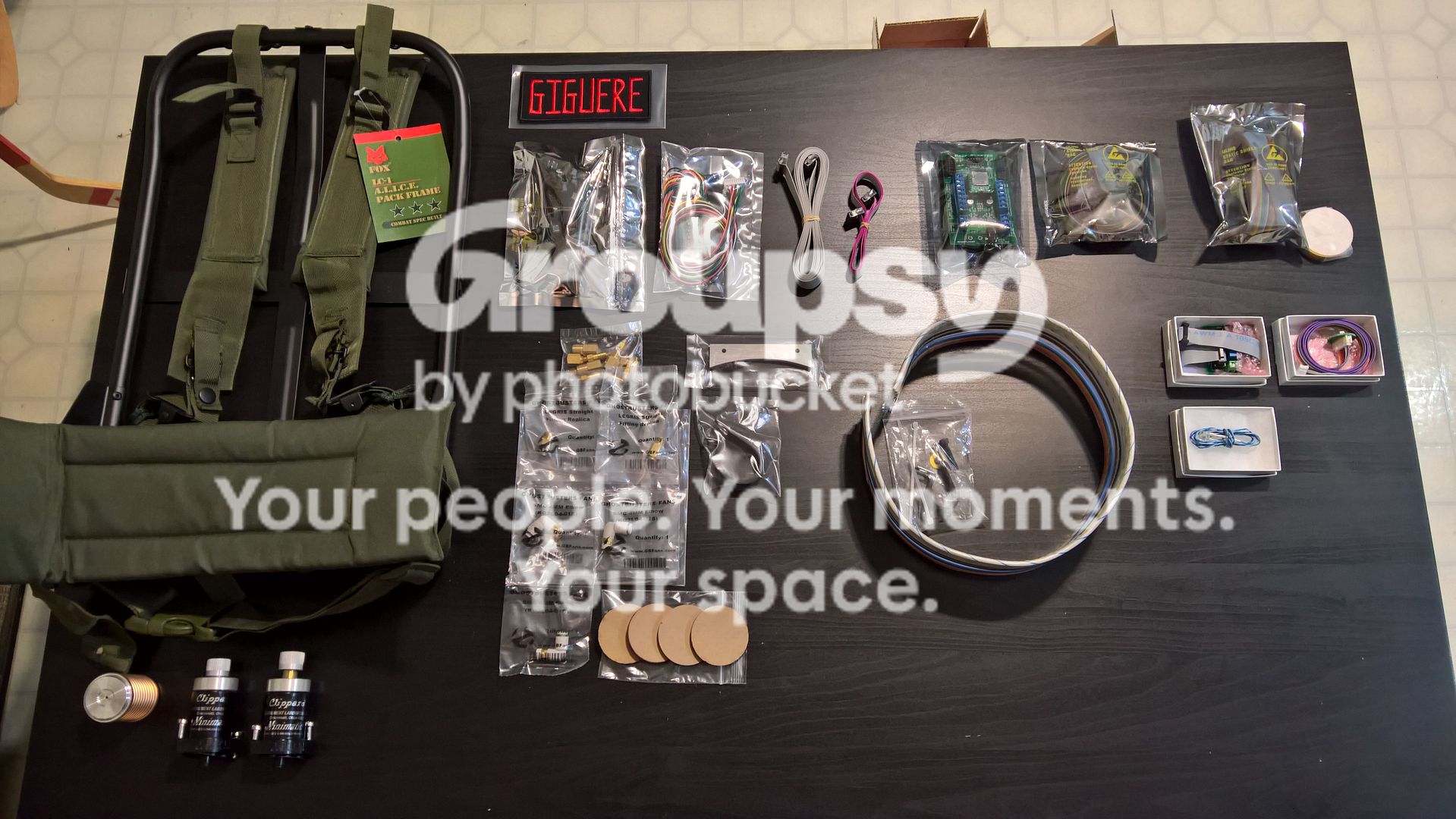
GBFans Order:
New old stock ALICE LC-1 Frame and used LC-1 straps:
Blue brick 12V battery, Deluxe Spengler plate and wiring set, 6.5" and 4" speakers at 4 ohms impedance:
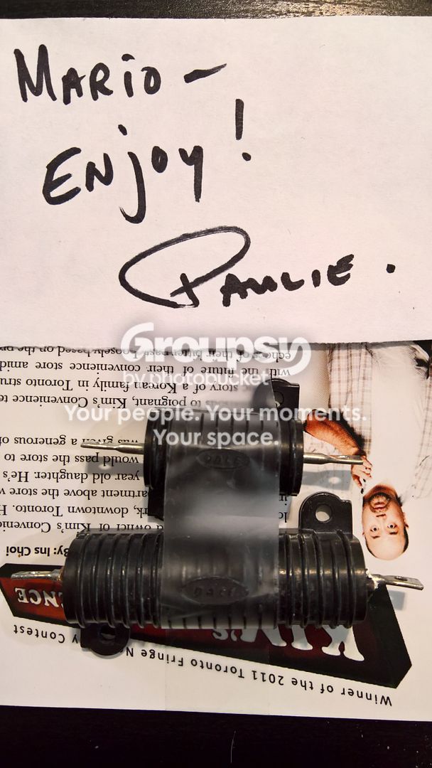
Dale RH-25 and RH-50 resistors (so generously provided by Naptime):
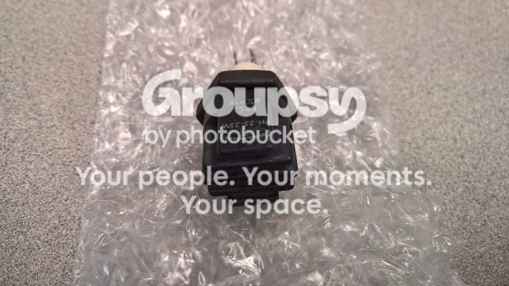
Dalohm PH-25 resistor (Dreamstalker)

[/list]
Links in this post may be affiliate links. Purchases made through them help support this site at no additional cost to you.
Hooray! You’re about to begin! That Benofkent shell looks great! Did they do the pre-mounting of the mobo for you? Love, love, LOVE the shots of all your parts.

I’ve got a Benofkent pack and yes, he mounts the mobo to the pack for you.

Amazing service from Ben, can’t recommend him enough.

As Jonobiwan stated, Ben pre-mounts the shell to the motherboard. Ben’s service is incredible, just like his communication. Whenever I have a question or concern, he usually responds within minutes. This is quite a feat, considering there is an eight hour time difference between us!

Speaking of Ben’s service, your question (and response) is a perfect segway into my next update.

I had originally ordered a kit from Ben’s July run, but due to an unforseen shell mould failure, my kit was delayed until August. Ben let me know as soon as it happened and he explained that he would use this opportunity to improve his shell. I was happy to be one of his first customers to receive his Mark 2 shell.

There was second delay in receiving my shell, but this one was not Ben’s fault. The courrier service that Ben uses, UKMail, dropped the ball by incorrectly registering my parcel in their tracking system. The result was that my package sat in a warehouse for a week without being processed. Despite working on a number of other kits, Ben monitored the shipping situation and contacted UKMail as soon as he perceived that something was wrong. Thanks to his quick action, UKMail realized their mistake and rushed the delivery of my parcel (even though the tracking number didn’t really work). In the end, I received my package through DHL here in Edmonton, Alberta, Canada.

While waiting for the kit to arrive, I started to be proactive on my kit build and I started working on three things: 1) reinforcing the vertical support bar on my knock-off ALICE LC-1 style frame from the GBFans Shop, 2) painting my cyclrotron reflectors in anodized red and 3) creating puck spacers that will be used between the ALICE frame and the aluminum motherboard.

Reinforcing the vertical support bar on the ALICE pack frame

This experience is a lesson learned that I don’t recommend repeating!

As a number of builders have noticed, the vertical support bar on the knock-off ALICE LC-1 frames are rather flimsy. Inspired by Steve and Jimm’s dual proton pack build thread at Steve and Jimm's Dual Proton Pack Builds - Proton Packs - GBFans.com and Mat’s Pack Build at Mat's pack build! - Proton Packs - GBFans.com, I decided I was going to replace this bar with a thicker and sturdier steel bar.

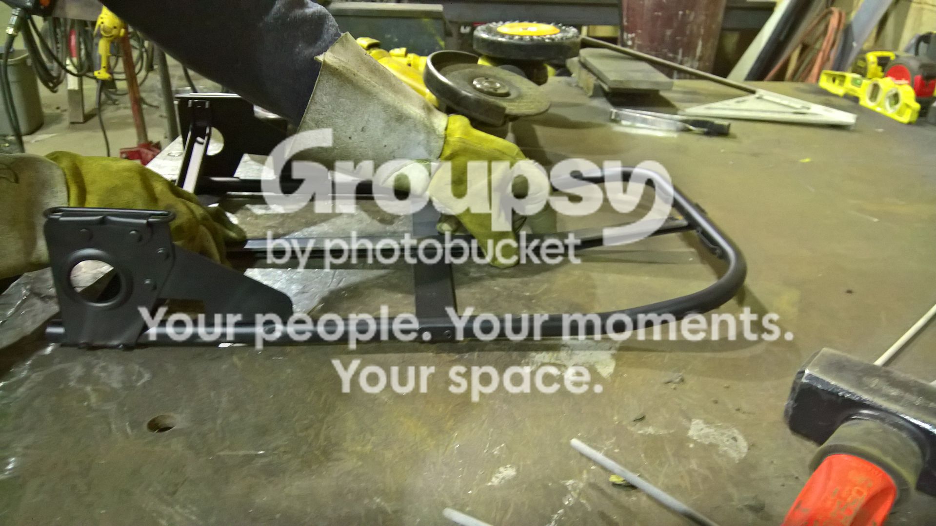
I was going to do this with a friend of mine who happens to be a welder. However, once we arrived at his shop, we realized that we did not have any rivets to secure the new steel bar to the frame. We decided that we would reinforce the existing steel bar with a larger and thicker one by welding them together, like so:

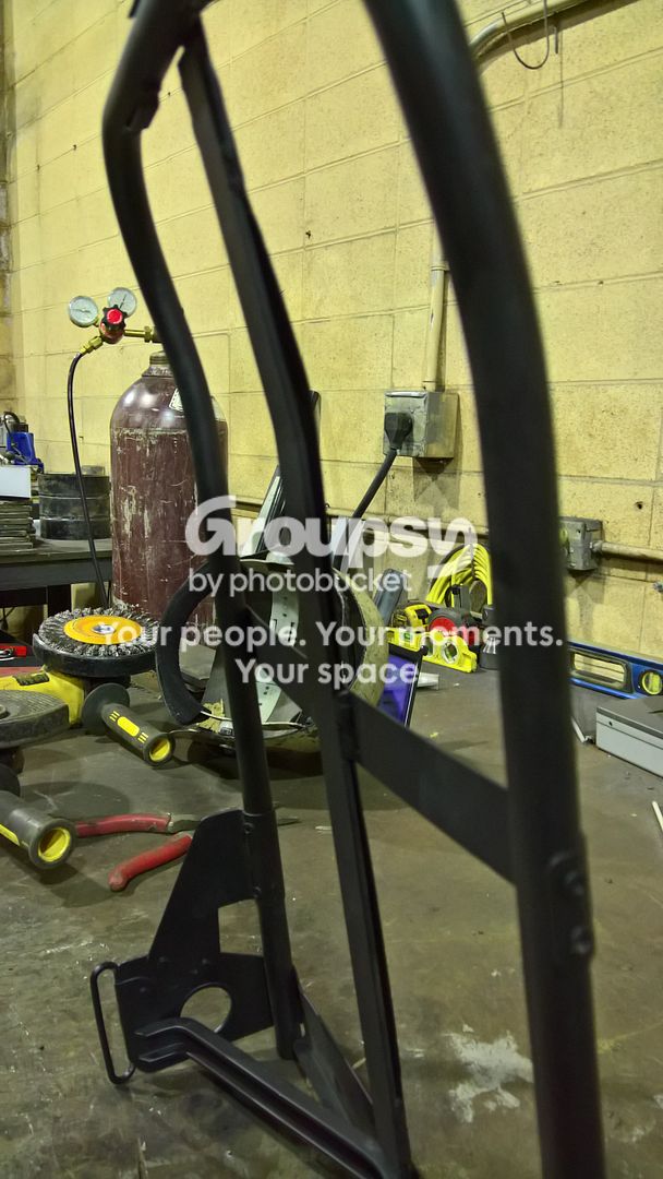
The benefit of this method was that the original vertical bar no longer moved and the frame felt much sturdier. The drawback, however, was that it added more weight to the frame. Furthermore, I did not foresee the gap that became quite apparent between both bars, especially at the bended area:

In terms of esthetics, this was not a good solution. We spray-painted the steel bar in a matching flat black colour and I was planning to fill the gap with some Bondo, as many people have been doing with gaps in their shells, but the difference in the look would always be apparent.

In the end, I found an new old stock ALICE LC-1 frame from a supplier on eBay that included the LC-1 shoulder straps, waist strap and kidney pad that I was looking for, so I decided to order it. Although this was a large and unforeseen expense, I was very happy with my decision. The new old stock frame is much sturdier and the vertical bar is already quite a bit thicker. Since this is an original frame, I don’t have to worry about the inaccuracies from the knock-off frame, namely 1) the bevel in the lower section of the vertical support bar (the original doesn’t have one there), 2) the reversed (or inverted) bevel in the top portion of the vertical support bar (the original has a bevel sticking outwards away from you rather than inwards towards you), 3) drilling holes in the lower section of the frame in order to mount the motherboard (the original already has two slits in order to fit your bolts and spacers).

Painting the cyclotron reflectors in anodized red

While planning my kit build, it took me a while to decide whether or not I should include the cyclotron light kit of the 2009 video game because I wanted the look of my pack to ressemble those that were used in the original Ghostbusters movie. My dilemma was the following: if I used the TVG light kit that I had purchased from Spongeface, I would need to use clear lenses and therefore the cyclotron would not be red when the pack is turned off. Of course, if I used red lenses like those used in the original packs, the color of the lenses would interfere with the colour eminating from the RGB LEDs in the TVG light kit.

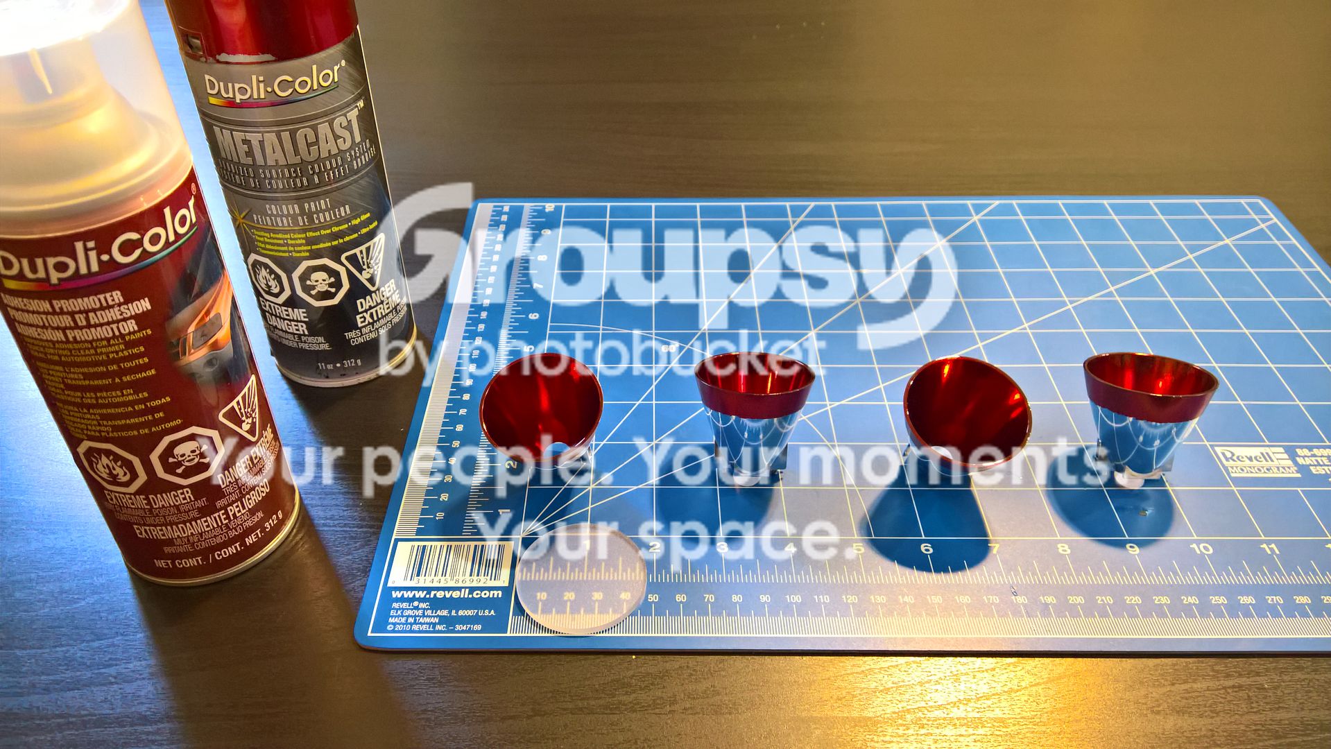
Thankfully, I came across Phil’s GB1 Hero Pack Project 2014 build thread at Phil's GB1 Hero Pack Project 2014 [High-Res Photo Heavy!!!] - Proton Packs - GBFans.com, where he adopted an idea used by father and son Fincher team (Charles “Sephiroth” Fincher) in their proton pack build. Their solution was to paint the four cyclrotron reflectors with an anodized red reflector spray paint that will make clear lenses look red when the pack is turned off. The reflector paint won’t interfere with the TVG colours of the cyclotron light kit (if they do, Phil assured me that it is to the smallest extent). Utterly brilliant! Here are the reflectors that I painted:

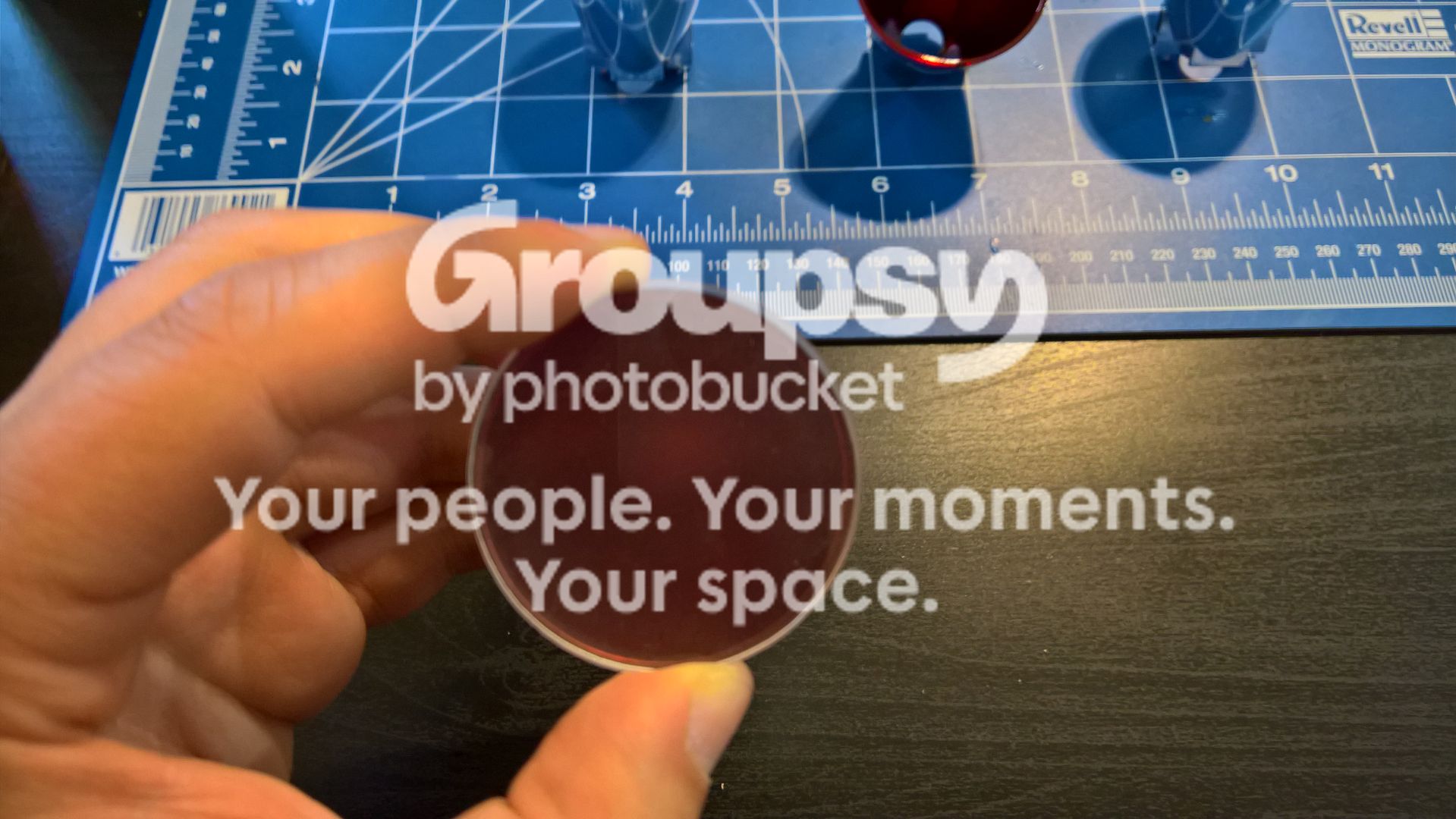
As you can see in the next photo, I chose to use a clear frosted lens for the four cyclotron lights and I think the results look really good. I can’t wait to see what they look like with the electronics!

Creating spacers with hockey pucks

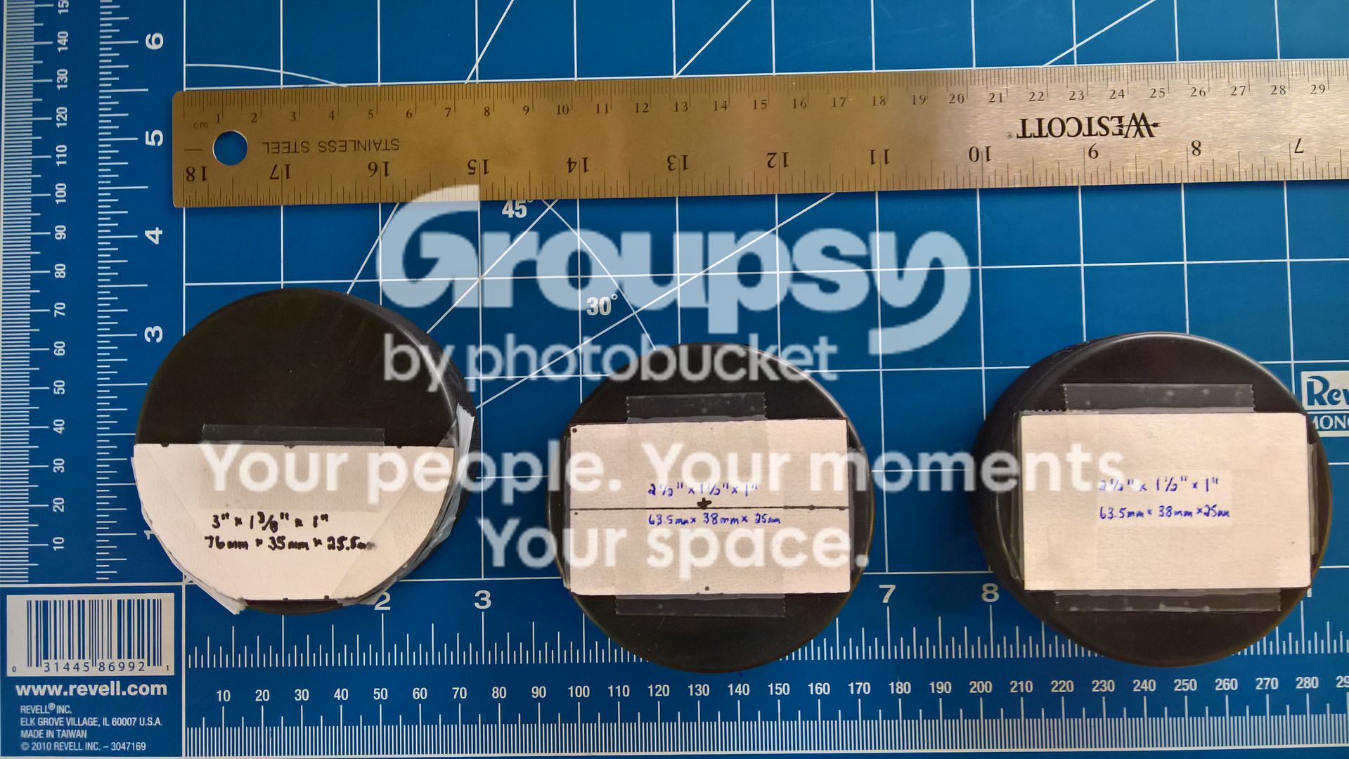
I came across this idea while reading PssdffJay’s Proton Pack Build Thread at PssdffJay's Proton Pack Build (Pic Heavy) Yay updates!! - Proton Packs - GBFans.com, which he took from Julz’s Ye Olde Half Moon GB1 Spacer thread at Ye Olde Half moon gb1 spacer - Proton Packs - GBFans.com. The dimensions I used are probably not screen accurate, but since these are spacers made from hockey pucks, I decided to use measurements that were convenient. Here is a photo of my templates with the dimensions written upon them (in both millimeters and US inches):

Rather than using a hacksaw and a mitre box to cut the rubber from the hockey pucks, I used a grinder while I was at my friend’s shop (the welder that I mentioned earlier). This created a lot of smoke, so it was important that the garage doors were opened and the fan was running.

The results are good, but the edges of the cuts are not totally clean. I will have to retouch one bottom spacer in particular, since it ended up being slightly taller than the other. I’m not too worried about it for the time being, though. I will edit this post with another photo once I have touched it up.

Got some great looking parts from some great sellers there. Really looking forward to this build. Good luck!

I love the puck idea.

Might have to see if Jay has any pucks left. Eheh.

Does Edmonton Nut & Bolt do walk-in service? I was going to hit up Acklands-Grainger for cap screws tomorrow for my SC shell build but they sometimes need to special-order their stuff.

Yes! As far as I know, they only do walk-in service. However, they are only open from 7:30 to 5:00 on weekdays, which really doesn’t jive well with my schedule. It’s well worth their prices, though.

Great start so far! But I’m jonesing for more build photos…

I should have followed your lead. Acklands has all my needed cap screw sizes, but they are strewn in a bunch of warehoused across the Prairies. Fastenal won’t sell to the public, and Edmonton Fasteners only goes as small as 1/4-20.

At least Acklands can get them shipped in within 3-5 days, so all hope is not lost. And I certainly hear you about dealing with office hours only on weekdays…

Looking forward to more!

Try The Bolt Supply House. I’ve gotten some of my hardware there.

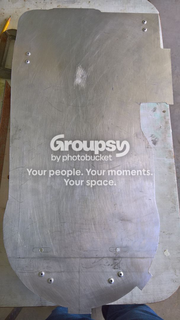
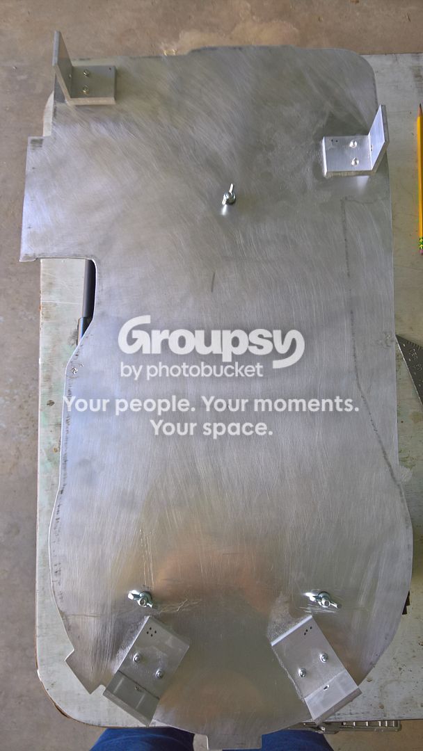
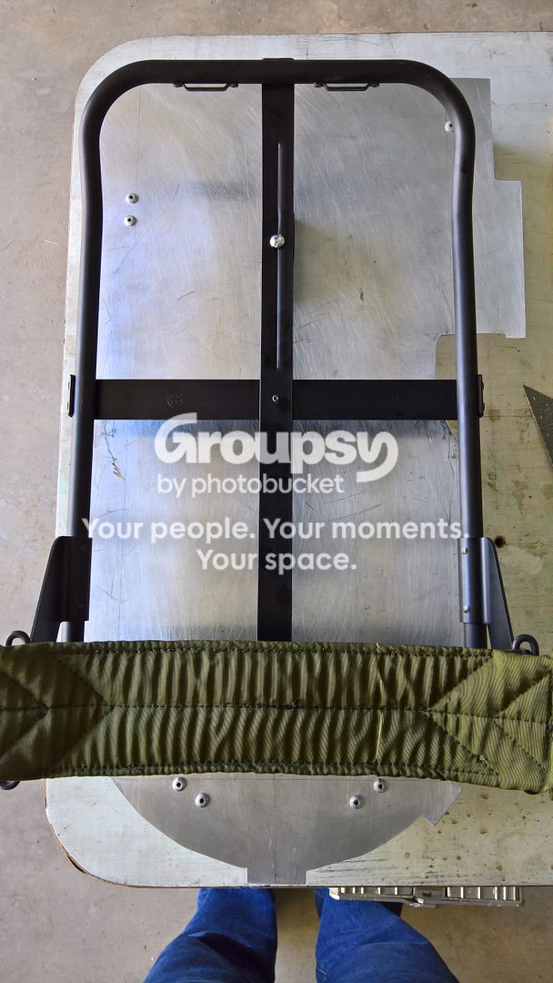
Today I mounted the aluminum motherboard to the ALICE pack frame.

The Benofkent Props kits do not include the bolts, washers and wingnuts that are required, so I looked at GohstTarp’s Proton Pack Build at GohstTarp's Proton Pack Build - Proton Packs - GBFans.com to find out which ones I needed:

  • 3 x 2" 1/4-20 round head Philips bolts/screws

5 x 5/8" OD, 1/4" IO washers

3 x 1/4" wingnuts or 1/4" nylon nuts

I went to Canadian Tire and bought the bolts and wingnuts, but I didn’t buy those particular washers. Instead, I used some split lock washers that I had lying around. Does anyone foresee any issues with this decision? I guess there is a risk that they may dig into the aluminum motherboard…

Moving on, Benofkent Props’ motherboard does not come with the three pre-drilled holes to serve as attachment points (as opposed to the GBFans motherboard, for example).

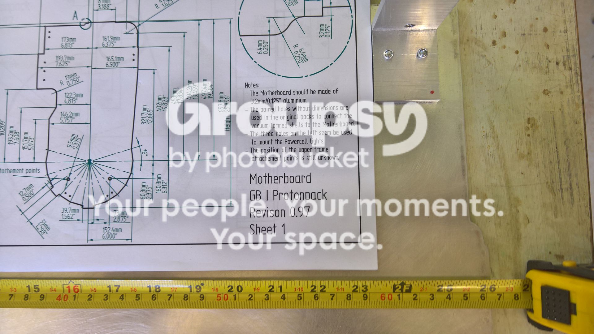
I thought I would to use the measurements in Stefan’s GB1 Proton Pack plans in order to locate the exact location of the attachment points, even though the plans clearly indicate that the upper attachment point is unknown. However, as soon as I measured the length of the Benofkent Propos motherboard, I realized that it is longer than the measurements in Stefan’s plans. As you can see in the photo below, the length of the motherboard is longer by about 4 mm. This is a pretty minimal difference, but it still freaked me out at first. Remember, I am a rookie with very little confidence when it comes to drilling holes in things!

I ended up drawing a vertical centre line (as in Stefan’s plans) down the length of the motherboard. Then I went off on my own, ignoring Stefan’s plans (meaning I wasn’t worried about screen accuracy anymore). I used the lower rivets on the motherboard (used to secure the shell mounting brackets) as a reference point and drew a horizontal line overtop of them. If you recall, Benofkent Props includes the shell mounting service with their kits.

After that, I drew a parallel line one inch higher from the lower rivets. This last line represents the lower extremity of the frame (the lower portion of the frame would line-up here). After lining up the frame with the vertical and horizontal reference lines, I traced the shape of the two ALICE frame slots (located on the left and right side of the lower pack frame–the rounded rectangular holes). As for the upper attachment point, I marked its horizontal location upon the centre pencil line that I had drawn earlier. I made a best guess in terms of its vertical location.

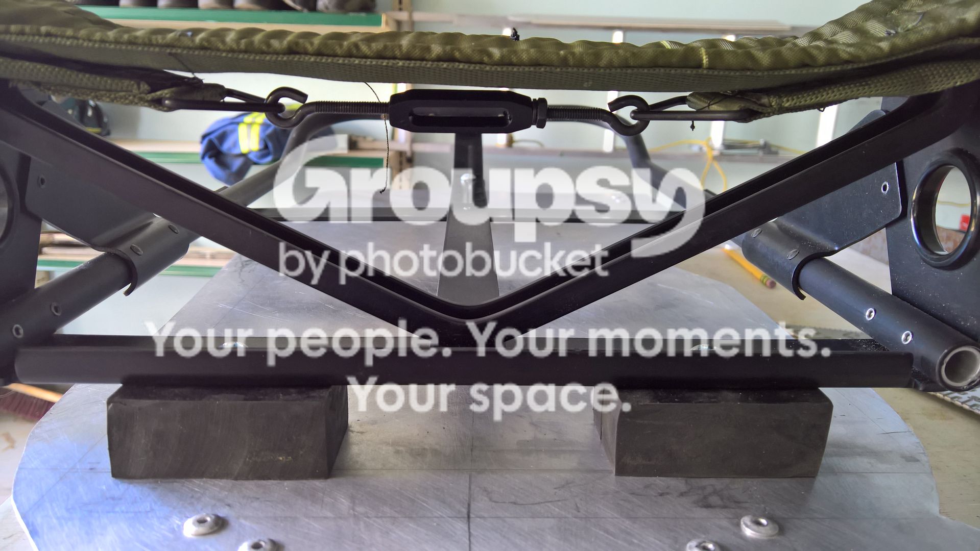
Once I drilled the quarter-inch holes through the motherboard, I mounted the motherboard to the frame in the following configuration:

  • Bottom two slots:

Bolt → washer → ALICE frame slot → rectangular spacer → motherboard → washer → wingnut

Top slot:

Bolt → ALICE frame vertical bar → half-moon spacer → motherboard → washer → wingbut

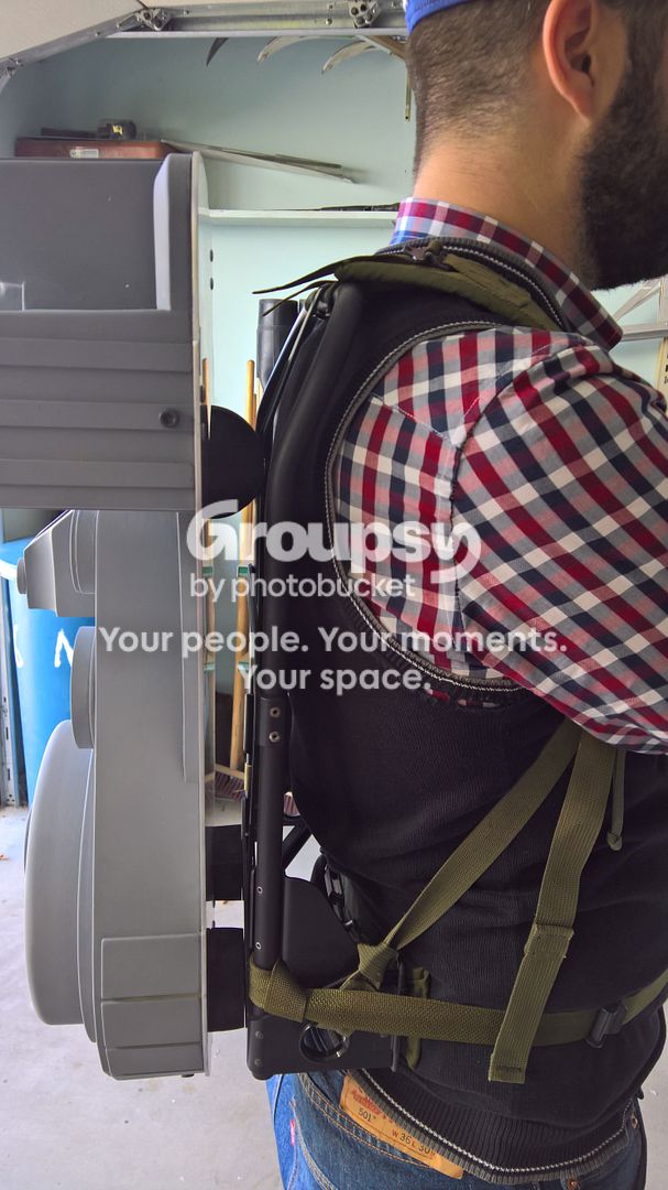
Once the frame was attached to the motherboard, this is what it looked like (view from the inside of the pack without the shell):

Here is a view from the flip-side:

A view from the bottom:

And lastly, a side view:

In that last picture, you’ll see that there is a slight gap between the half-moon spacer and the motherboard. I later corrected this gap by turning the spacer 180 degrees.

Any thoughts? Judging from the pictures, does everything seem to align properly? Anything I should correct?

It looks pretty good. It’s hard to tell if yours is higher than mine without measuring but I’d have to open it up to do that. Here is a pick of my holes (Gbfans motherboard).

It does look like its riding high on your back. I do think your shoulder straps need to be looser on the top strap but that’s more on preference. What does it look like from the front? Straight forward? That’s a good indicator of how high it is based on how much is higher than your shoulder, but again personal preference. My preference would be that it should be at the top of the collar of the short you’re wearing in that photo.

fantastic build!

I’ll try to get some pictures for you this evening! I hastily put on the straps in those pictures, so they weren’t adjusted and they definitely need to be looser at the top.

What do you guys think of the horizontal (x-axis) length of my half-moon spacer? Does it look too long in the pictures? In other words, should the motherboard be leaning a little more towards my back near the top of the pack frame?

Thanks again for the feedback!

While a friend of mine was over last night, I forgot to ask him to take some pictures with font and back profile views of the pack on my back (to judge how high the pack sits relative to my shoulders).

Nonetheless, I did get some work done.

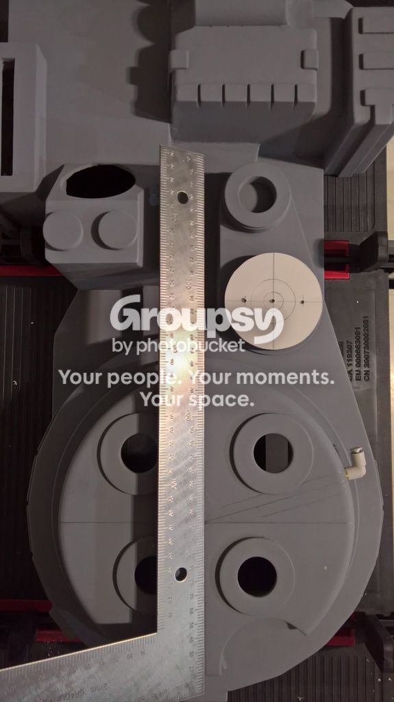
The first thing I did was to locate the centre of the cyclotron. While this sounds simple, I didn’t find it easy or obvious. While this may be elementary to most people in this forum, I will share my experience so that it may help someone else who has the same skill level as I do.

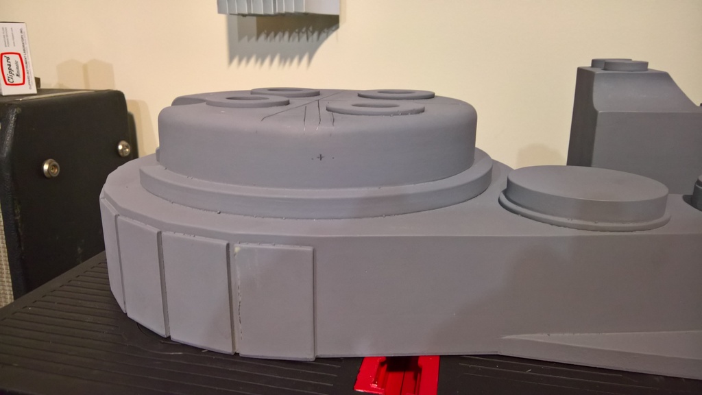
I decided to start by making a template out of thin cardboard (perhaps its poster board). First, by measuring the diameter of the cyclotron with my digital caliper (229 mm or 9"), I was able to determine the radius (114.5 mm or 4 1/2"). From there, I located the centre by tracing a cross between opposite corners of the square, which separated the template into four triangles. Using my pencil, I punched a hole in the centre, which I could then use to mark the centre directly onto the pack shell. Then I drew addition reference lines to separate the template into quadrants. These additional reference lines represent the cross that I wanted to draw onto the cyclotron, so I punched holes at places along these lines as well. By referring to Stefan’s plans, I knew that I needed to draw a line from the centre that goes up 16 degrees through the upper right quadrant in order to determine the location of the cyclotron elbow. Using a steel protractor, I traced the outline of the steel arm. The middle of the two parallel lines of the steel arm would be the 16-degree line to the elbow.

![image](http://www.gbfans.com/images/pb/canpara/WP_20160930_21_05_21_Rich 2_zpswjmsdeje.jpg)

While lining-up my template over the cyclotron, I found it somewhat difficult to square-up the vertical and horizontal lines or the template to the shape of the shell. Using my set square, I was able to make a relative “best guess.” Then I marked the shell through the holes of the template with my pencil and then I traced the lines on the shell with a ruler.

Then, on the right side of the cyclotron, I determined the height of the elbow. The height of the cyclotron line-up nicely with Stefan’s plans, which are 50.8 mm or 2.0" from top to bottom. So, the height of the elbow was 17.5 mm or 0.689" from the bottom of the 12.7 mm or 1/2" ledge.

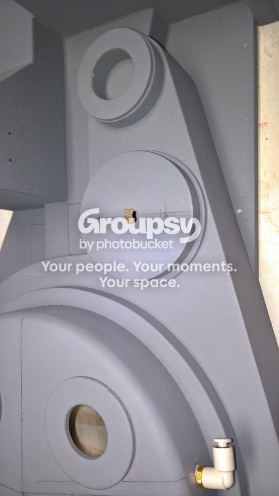
Now I know the location of the elbow. The elbow I am using is an SMC 4 mm elbow that I purchased from the GBFans shop. The next step is to drill and tap a hole in the shell in order to screw the elbow into the shell.

Using my caliper, I determined that the elbow is 3/8-inch wide. Therefore, I needed to drill a 5/16-inch hole and use a tap with the nominal size of 3/8-16 NC. NC is an acronym for National Coarse and it refers to the thread.

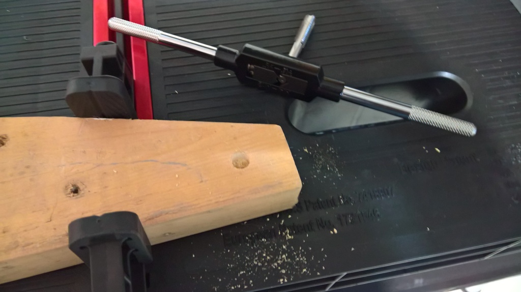
This is my first time drilling a hole in my shell and this was my first time tapping anything in my life. Before tempting fate onto my shell in the first attempt, I decided to practice on a piece of wood. I am so happy that I did… My second trial on the piece of wood was much more successful than my first attempt.

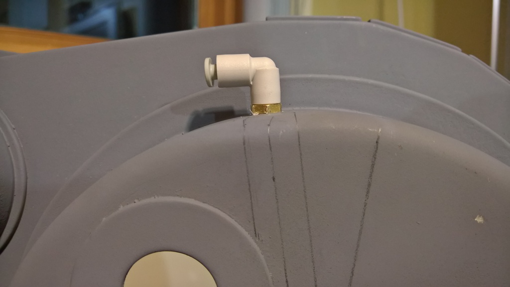
Having built up my confidence, I drilled a hole through the shell and screwed in the elbow:

I had no problem drilling a hole through the polyurethane shell. I never drilled through fibreglass before, but I never had the impression that the polyurethane was going to crack. While drilling the hole, I realized that the shell is much thinner than Naptime’s shell (he uses a pchrisbosh1 fibreglass shell).

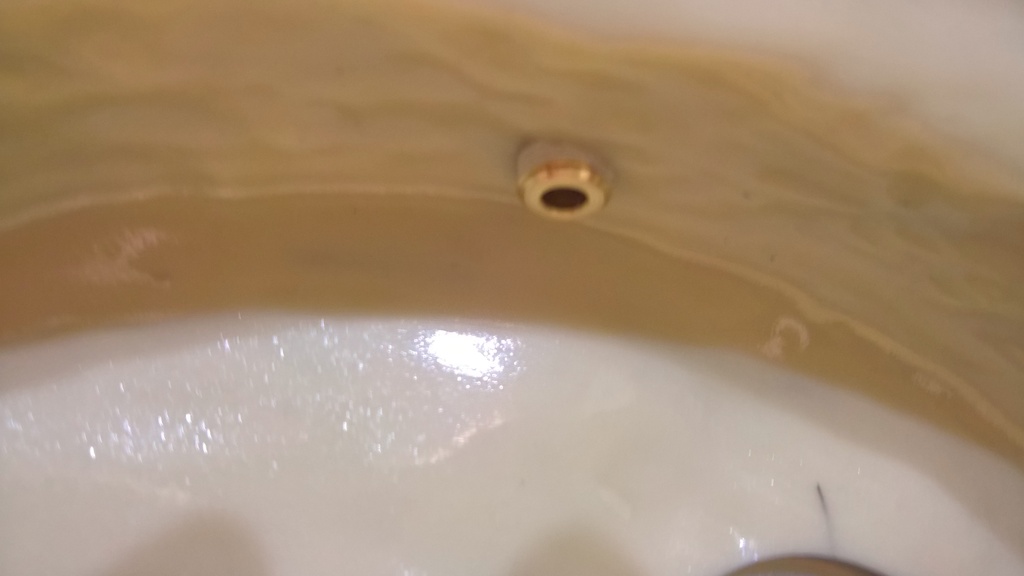
Here’s a view from the inside:

The elbow screwed in very well. At first, I thought the tapped hole was very tight and it was difficult to screw in the elbow. After applying a little more pressure, the elbow screwed into the hole and it was very snug.

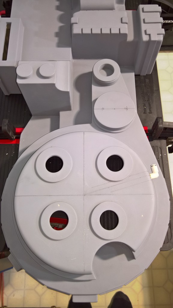
Here is a top-down view of the whole shell with the elbow:

You will notice that I marked the centre, the holes and the extremities of the Clippard valve. It was getting late, so I will continue that another day.

Nicely done.

A tip if you’re going to be tapping aluminum parts. Go get some cutting oil from Home Depot. It will really help.

Sage advice from Jay! A couple of times my tap bit got stuck in the middle of threading the aluminum. I really could’ve used the oil then.

I also have to thank you for providing such a comprehensive list of bolts - sizes and lengths! I used your list on my visit to Fastenal to get the hardware I needed to start attaching my aluminum parts to my shell!

Your shell work is immaculate! Well done, Mario!

A little update for you guys…

After seeing Jordin’s Freeky Geeky neutrino wand in person over the weekend, I splurged and I decided to get in on one of umoribar’s discounted Freeky Geeky proton gun and parts run packages. I should be receiving it in two to three months. I have updated my parts list (in the first post of this thread).

I chose the following options:

  • All holes drilled, including the vents

Screen accurate pinch to the front and the rounded base

GB-1 style no knurl on the side discs

Removable back on the trigger box

Milled right ear

1/8" hole in the left ear

Knub holes drilled at 9 & 12 o’clock

Egon disc instead of the gun track support block

Bar graph cutout to match Spongeface’s bar graph bezel kit. I measured my bar graph bezel to be 38.3 mm x 9.6 mm, which is 1.51" x 0.38" in inches.

I decided against ordering the hollow rear cylinder and the hollow front cylinder, since I do not plan on installing an e-cig kit or a vibration motor in my thrower. I also decided against the chanfer edge on the trigger tip and the shaved 1/8" off of the front of the gun track.

There’s nothing like a Canadian Thanksgiving long-weekend to progress on a build. It’s time to post some updates!

About my templates… Well, I probably went a little overboard, but I made one for just about every hole that I needed to drill. I relied heavily on my shell measurements and Stefan’s plans. Or maybe I discovered that I like to draw…

I can plan my holes all that I want, but eventually I have to start drilling.

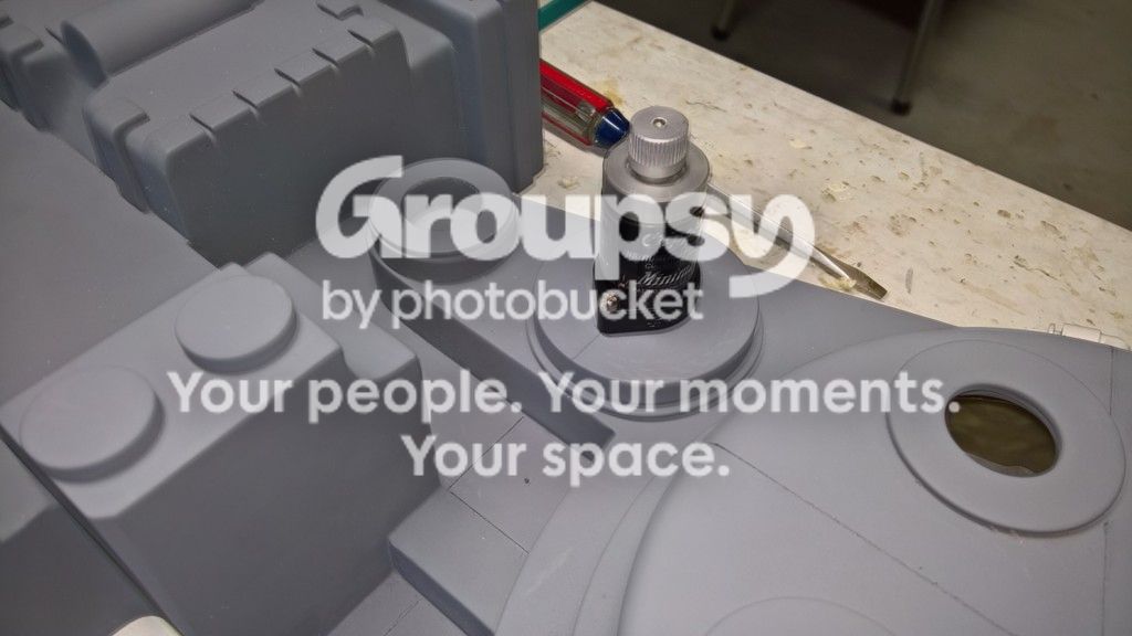
R-331 Clippard Valve

In an earlier post, I included a photo where I had marked the location of the holes that I needed to drill into the shell for the R-331 Clippard valve. I made these marks using a template:

As I drilled the center hole (using a 3/8” drill bit) for the Clippard valve, I adopted Naptime’s idea of cutting a little notch.

Using my sharpie pen, I put some black ink on the tips of the two screws. Once I placed the valve onto the proper location on my shell, the black ink of the screws left imprints that marked their exact locations. Since the nominal size of the screws are 3/16”, I drilled two 5/32” holes (one for each screw) on the ink imprints and tapped them with a 3/16” – 24 NC tap bit.

Here is the Clippard valve mounted to the shell:

Legris Straights

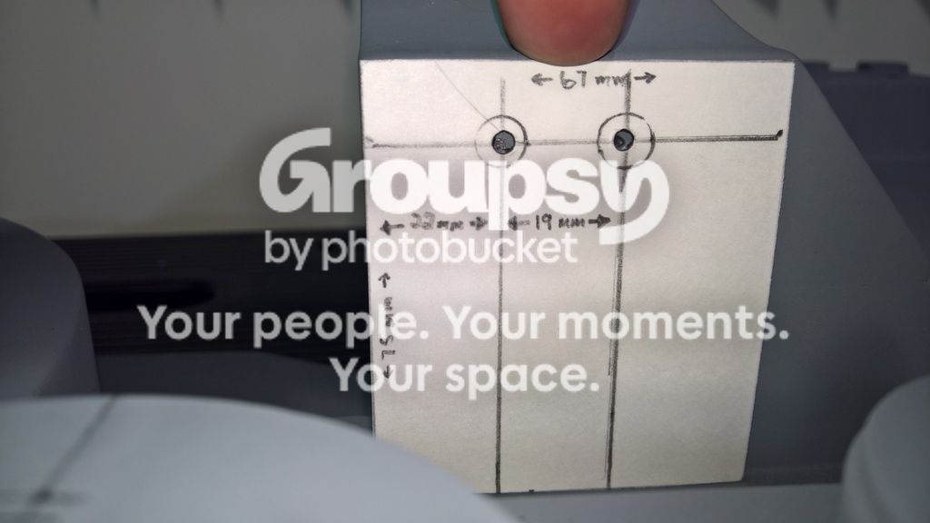
This is my template for the Legris straights:

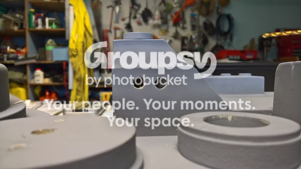
I determined that the nominal size of the threads are 25/64” wide, but I didn’t have the corresponding drill bits and tap sizes. So I tested a 3/8” hole in a scrap piece of plastic that I had lying around and it worked well. Then I drilled the holes in the shell:

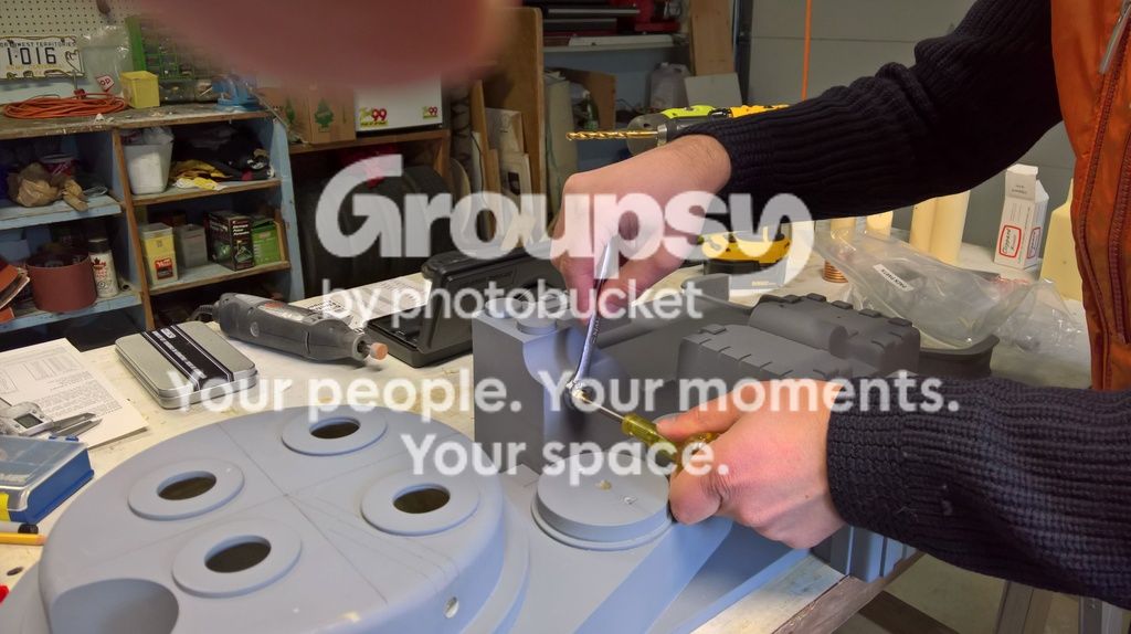
I screwed in the Legris straights by hand, like so:

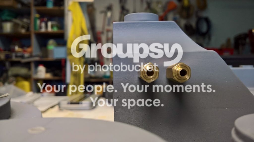
Finally, here is photo of the Legris Straights from outside the shell:

And inside the shell:

Holes for the Injectors, Beam Line and Filler Plug

Most of these holes are for 3/16" x 3" self-drilling roof screws with a rubber washer (two for the injectors, one for the beam line and one for the filler plug), so I drilled holes for them using a 7/32” drill bit.

Although I could have drilled the corresponding holes in the beam line and filler plug to mount them to the shell, I decided to wait until another day. I will have access to a friend’s drill press, which will guarantee straighter holes for these long screws.

Cyclotron and Powercell Lenses

Then I began working on the Cyclotron and Powercell lenses.

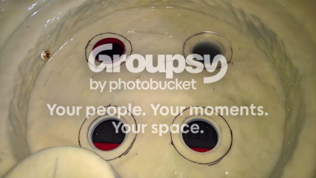
Benofkent Props’ shell came with pre-made lens recesses (from the interior of the shell) in which the Benofkent Props red cyclotron lenses fit perfectly. However, I decided to use a separate set of clear frosted lenses that are ideal for Spongeface’s Cyclotron TVG Colour Illumination Kit. The problem is that the clear lenses have a much wider diameter than the red Benofkent Props lenses.

At first, I thought I would solve this problem by adopting Naptime’s solution of widening the diameter of the lens recesses with the sanding tube attachment of a Dremel. I had worked out a method whereby I would stack metal washers (that are the same diameter of the cyclotron holes in the shell, which is roughly 30 mm) to the desired depth (the depth of the recess), glue them together, then attach them to a piece of scrap wood. The I would fit the washers through a cyclotron hole from the outside of the shell. Using a Dremel sanding disc, I would then sand out the polyurethane of the shell to the desired depth and width. The washers would prevent the Dremel from sanding too deep, this protecting the hole in the shell.

I know this would be easier to explain (and understand) if I had some photos or a video as a demonstration. Unfortunately, I do not. This is because I didn’ follow this method.

Contrary to my initial plan, there is much less risk of messing up the shell if I sanded down my clear lenses to the diameter of the pre-existing recesses. If something goes wrong, I figured it is much easier to replace a lens than it is to fix a shell. Therefore, I decided to sand down the clear lenses instead.

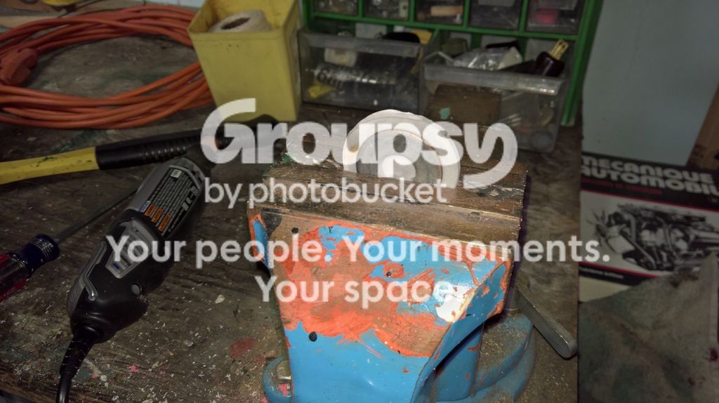
Using the washer that is the same diameter of the cyclotron light hole in the shell, I clamped it to a lens to it using a vice. I sanded down the lens to the desired diameter with the Dremel.

In the end, this worked well, with one exception. I accidently scratched one of the lenses with my dremel (I am still beating myself up over this one), but since the lenses are frosted, it might not matter. Once I have the lights installed in my pack, I might replace this lens if the scratches are noticeable.

.

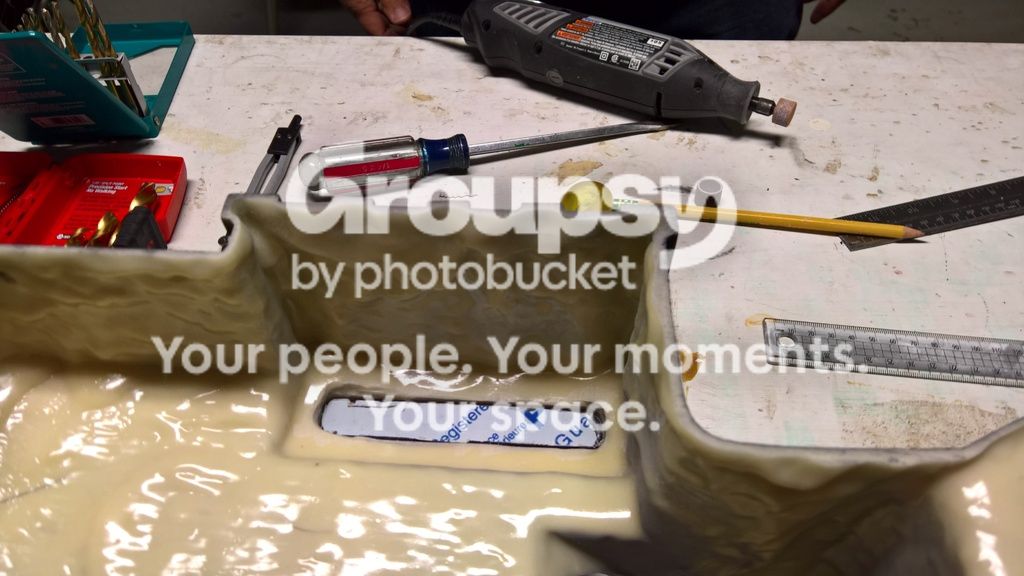
I used a similar method to sand down the large blue powercell lens that was included in the Benofkent Props kit. Instead of using a washer, I just marked down the measurements of the rectangular shell recess onto the protective adhesive plastic of the lens with a pencil. A word of caution: it is better to sand down the lens than to try to cut it. This prevents cracking.

Ion arm end cap, Dale resistors and Legris elbow.

Next is the Ion Arm.

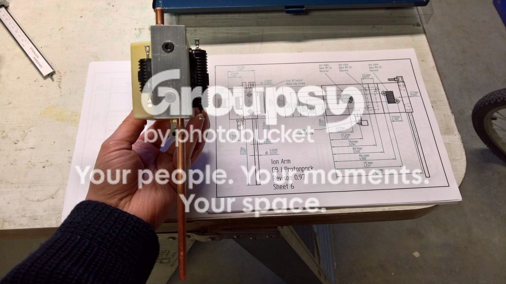
Although I didn’t mount the Ion Arm to the shell, I mounted the end cap, the Dale RH-25 and RH-50 resistors and the Legris elbow.

I started with the end cap, which I had just placed in its proper position and marked the holes with a pencil.

The two black ridged cap-style bolts that came with the end cap are M5 x 10 mm. I drilled a 5/32” holes into the Ion arm for each of the two screws and tapped them with a nominal size M5 x 0.8 mm. The holes that I drilled were 14 mm deep, so they were a little deeper than necessary.

You will notice in the photos below that I still need to drill a hole in the end cap in order to screw in the Clippard fitting. That will be for another day.

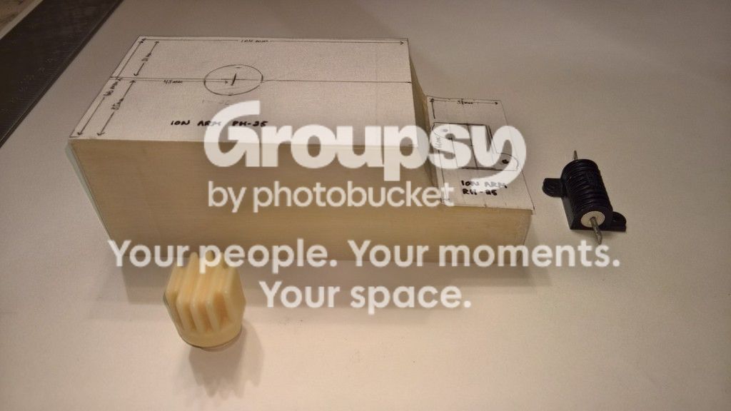
Here are my templates for the Dale RH-25, RH-50 and PH-25 resistors:

I have purchased an original PH-25 resistor (no ring variant) from someone here on GBFans, but I haven’t received it yet. I won’t drill the hole for this resistor until I have received the part.

In order to secure the Dale RH-25 and RH-50 resistors, however, I found some little screws in the garage that worked perfectly (I haven’t measured them, but I can if anyone is interested). For the two screws of each resistor, I drilled a hole with a 7/64” drill bit. Then I put in the screws manually with a screwdriver.

For the Legris elbow, I used the same 5/16” hole and 3/8”-16 NC tap that I had used earlier on the cyclotron.

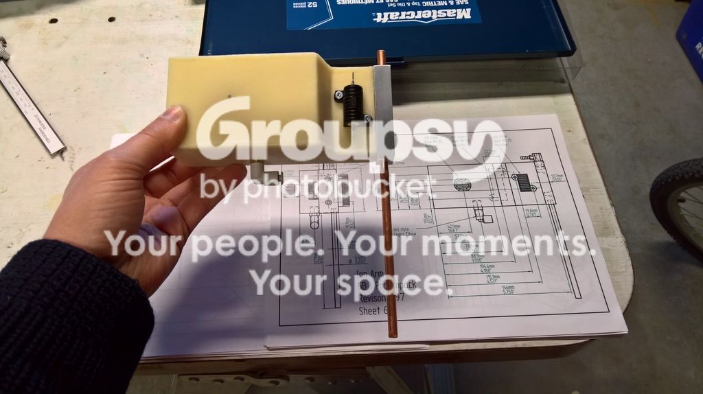
Here are the results, starting with a view from the front:

And one from the side: