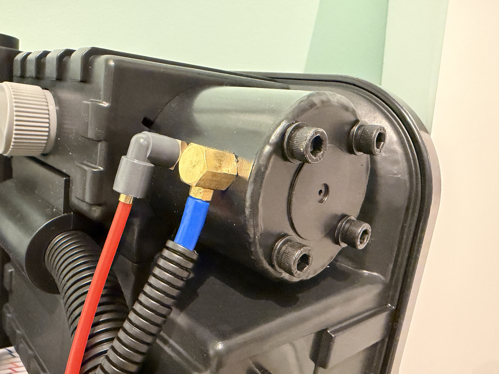
Hasbro 1984 Proton Pack BIG Overhaul and Customisation

Hi all,

I know I’m not the first to post about the new Hasbro 1984 Proton Pack, and I’m sure I won’t be the last, but I am just about to embark on a fairly big customisation project, so I thought I’d kick start a new thread to share my progress!

I modified a Spirit 1:1 pack a couple of years ago, but I didn’t really document my process that well, so this time, I’m going to try and give regular updates right from the start. I’m excited to get into it!

This time, I’m going for quite a ‘clean’, fresh 1984 look, as if the pack has just been built, so think Sedgewick Hotel. I’m actually quite happy with the outside of the Hasbro 1984 shell as I think it already captures this quite well, so I’ll be adding absolute minimal wear. It will be more about the fixtures and fittings.

I’ve already ordered a load of parts - Clippard valves, elbows, legris, lenses, hoses etc - I’ll share a photo of everything I’ve got so far once I start on the pack shell. I’ve also ordered a few bits from Redman Studio Workshop - aluminium motherboard, Alice frame mounts, V-hook, wand tip etc, but I’m still waiting for those to arrive, plus I’ve also ordered a GPStar 1984 Pack & Wand base kit, so I’m going to be doing some fun stuff with the electronics.

I’ve also already got a Hasbro 1984 wand, so I’ll be doing some work on that too to de-weather it and make some other small tweaks.

But one of the parts I’m actually weirdly most excited about is customising the cyclotron internals, using sites like The Ghostbusters Reference Library and their bit on the Afterlife pack as it was being built, so doing a version of that as if it had just been built.

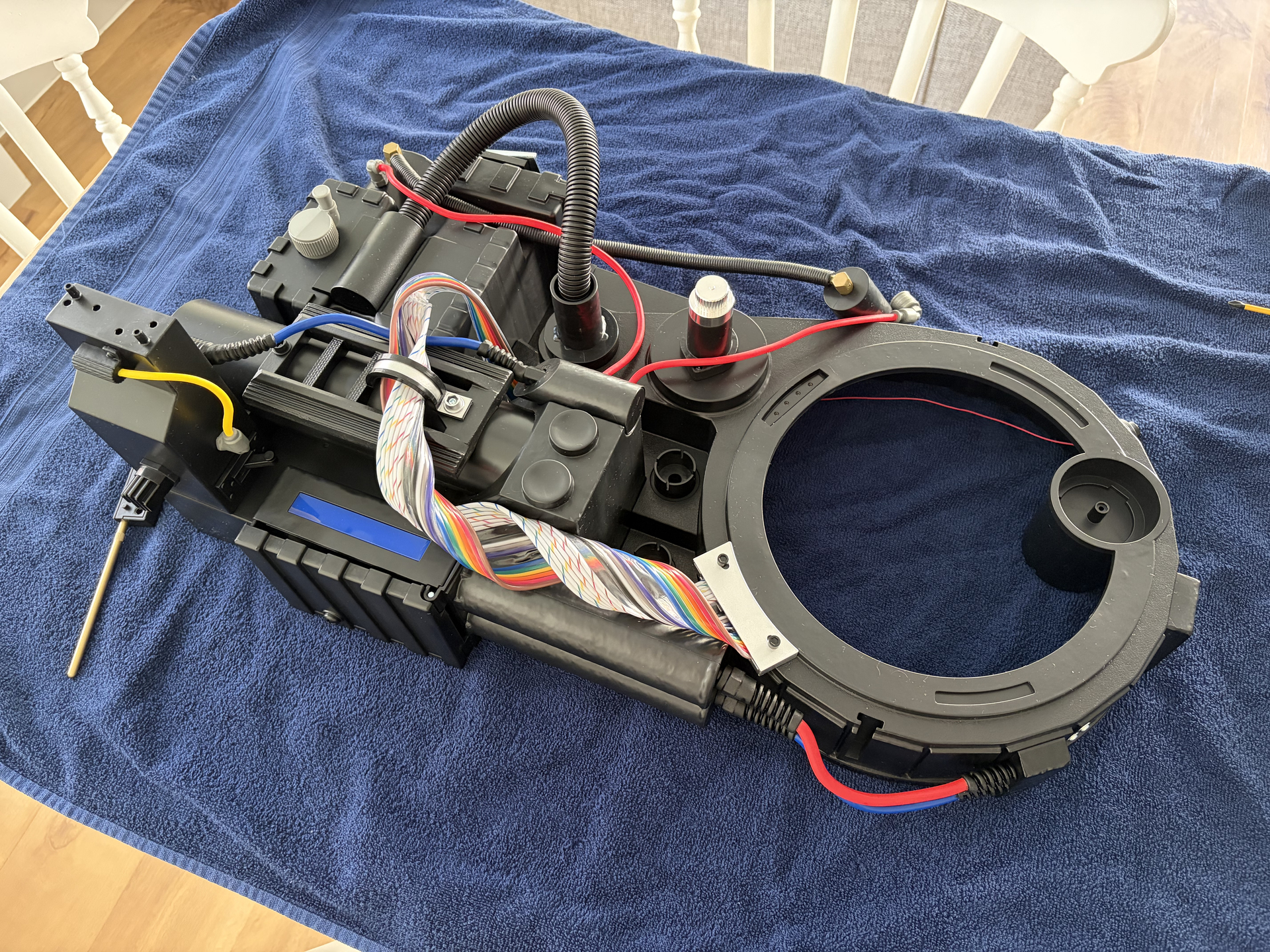
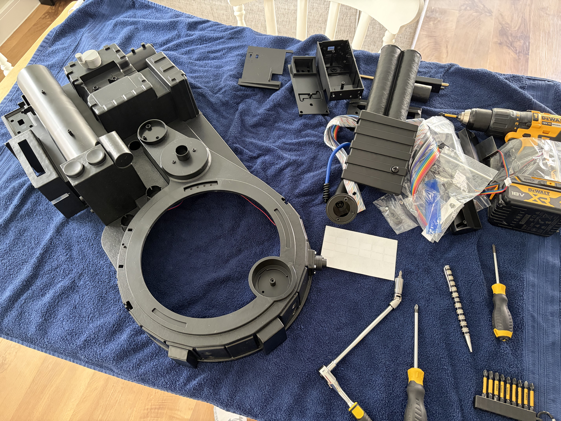
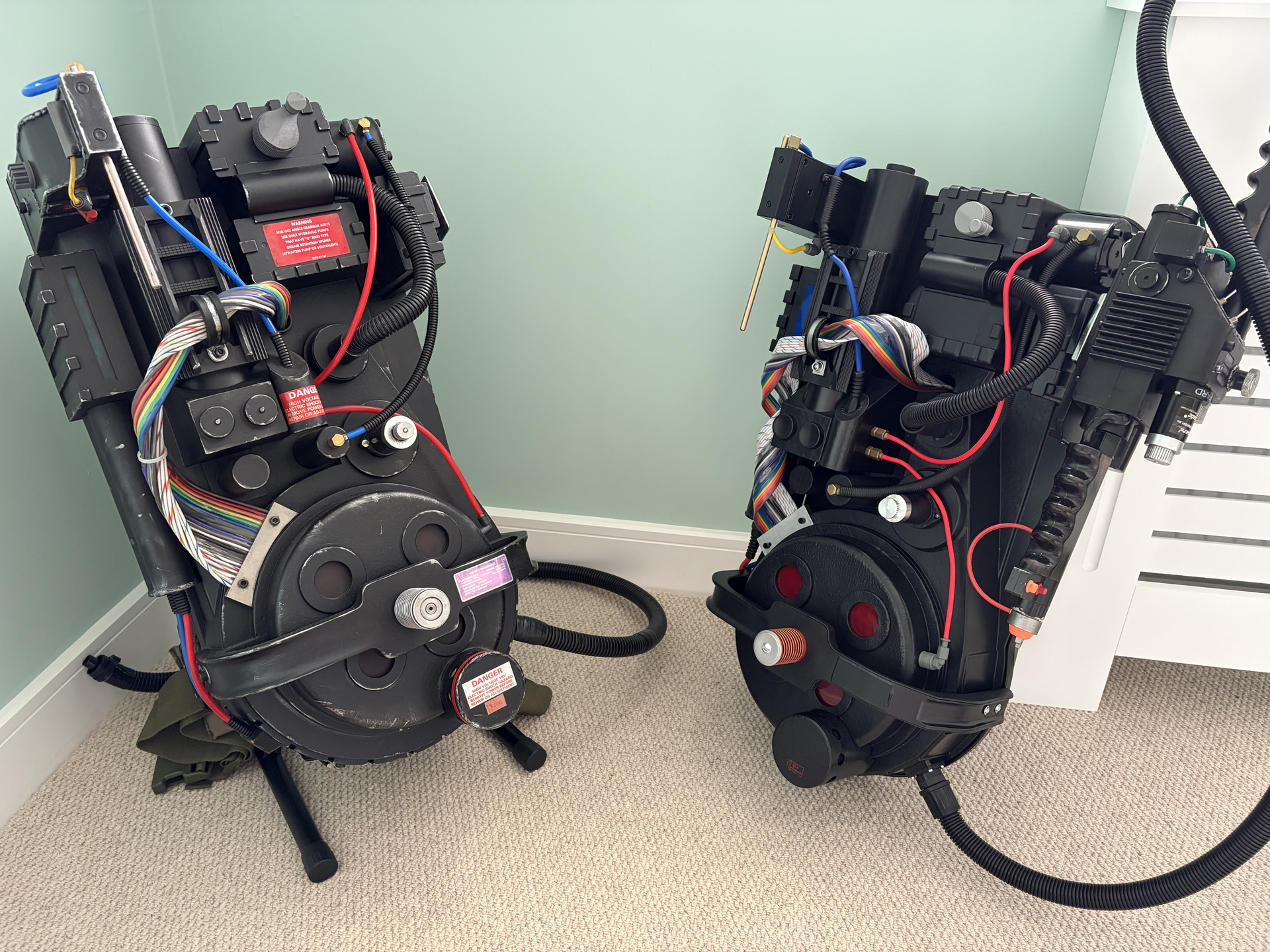
Anyway, to get things started, here are some standard pics of the pack before any changes, just so we can do a ‘before and after’.

Next to the modified Spirit pack:
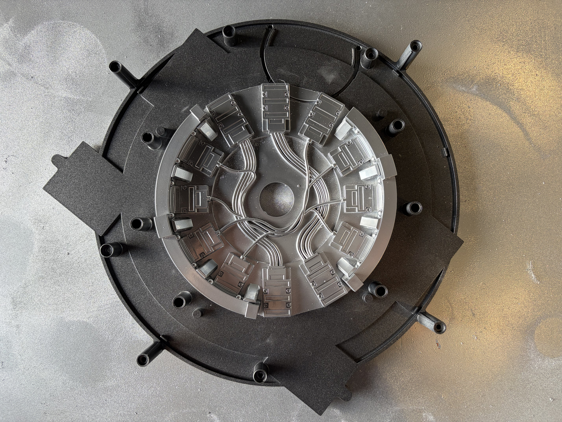
Inner cyclotron. Can’t wait to get rid of the cheap looking plastic:
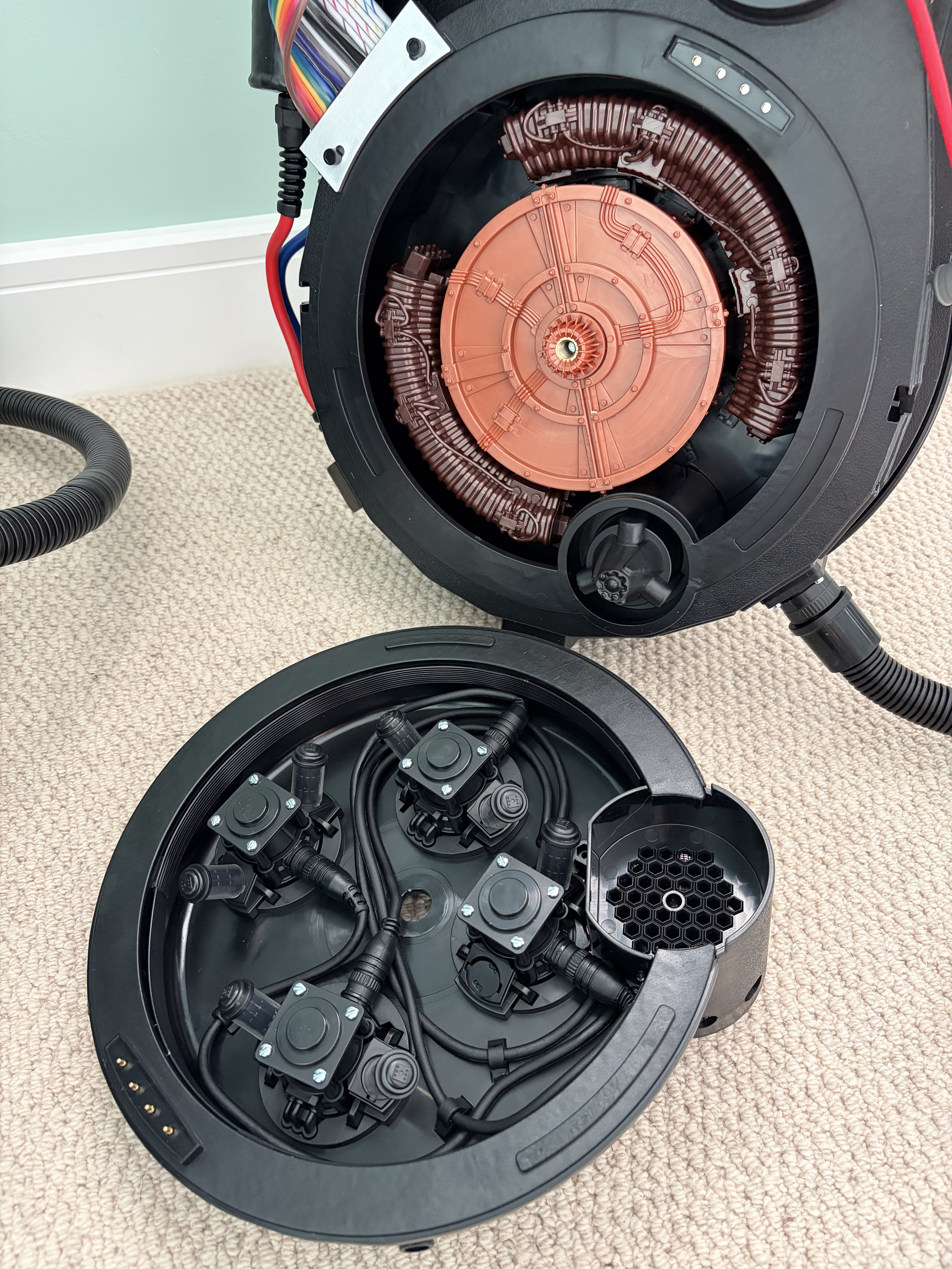
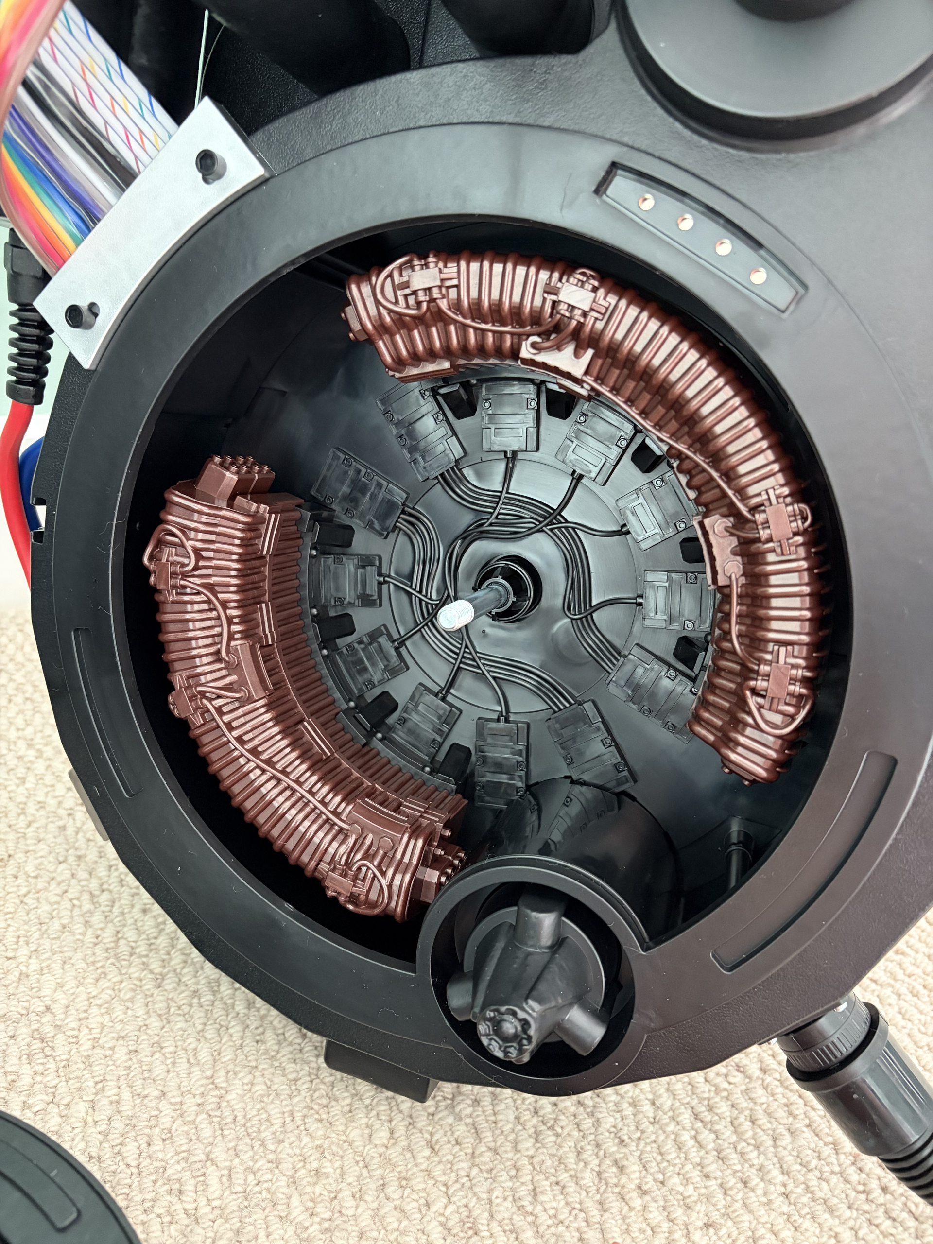
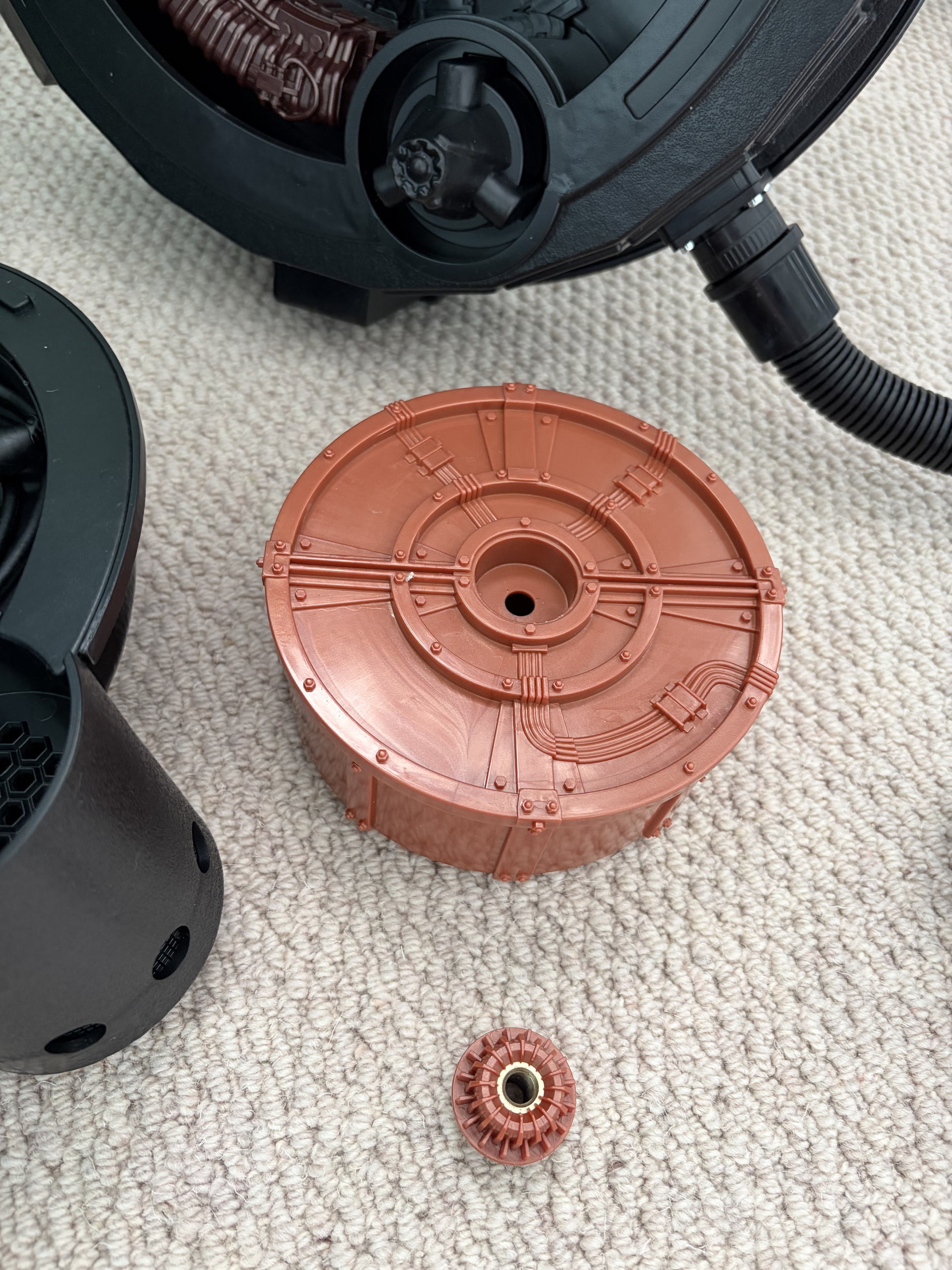
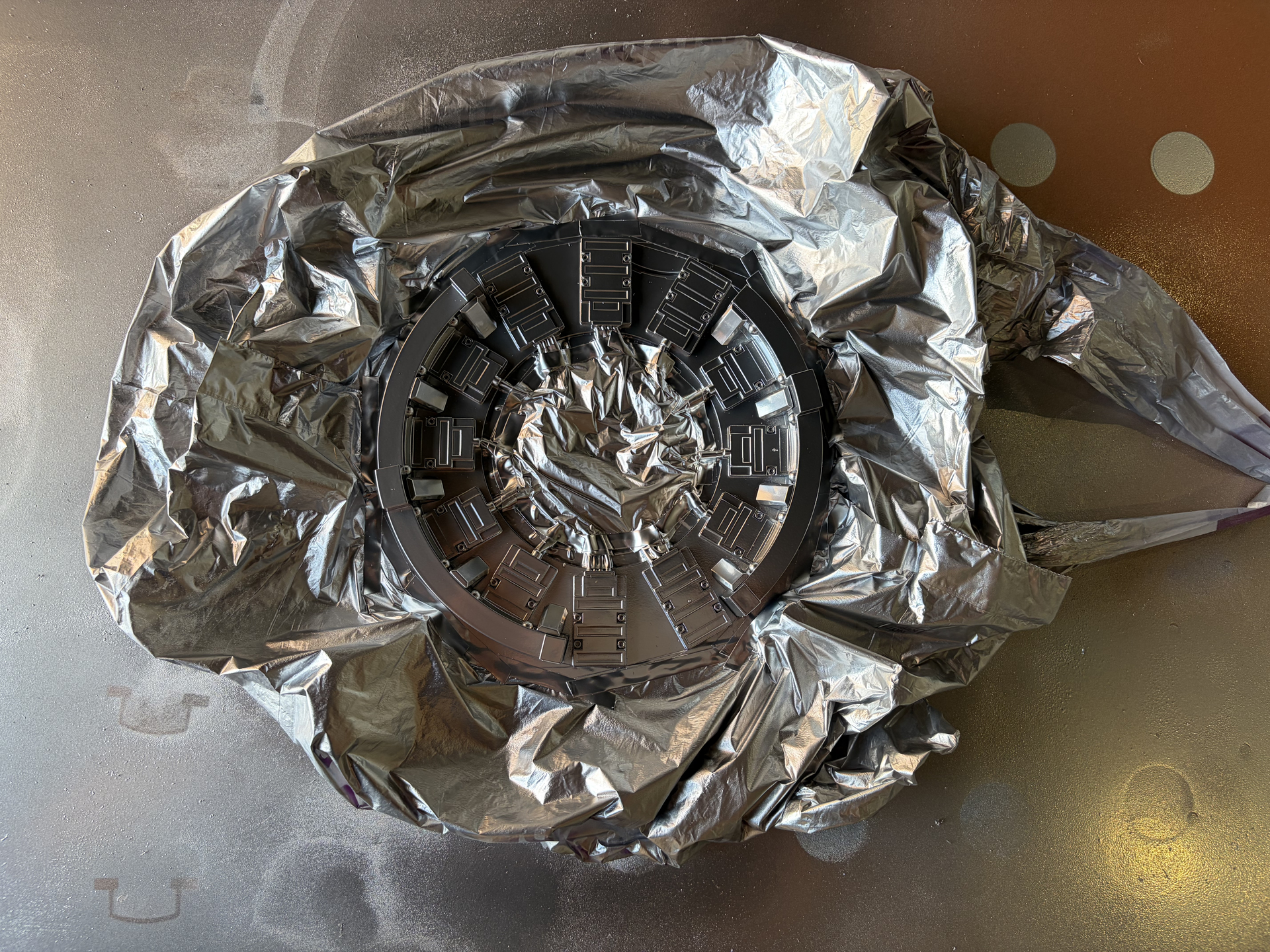
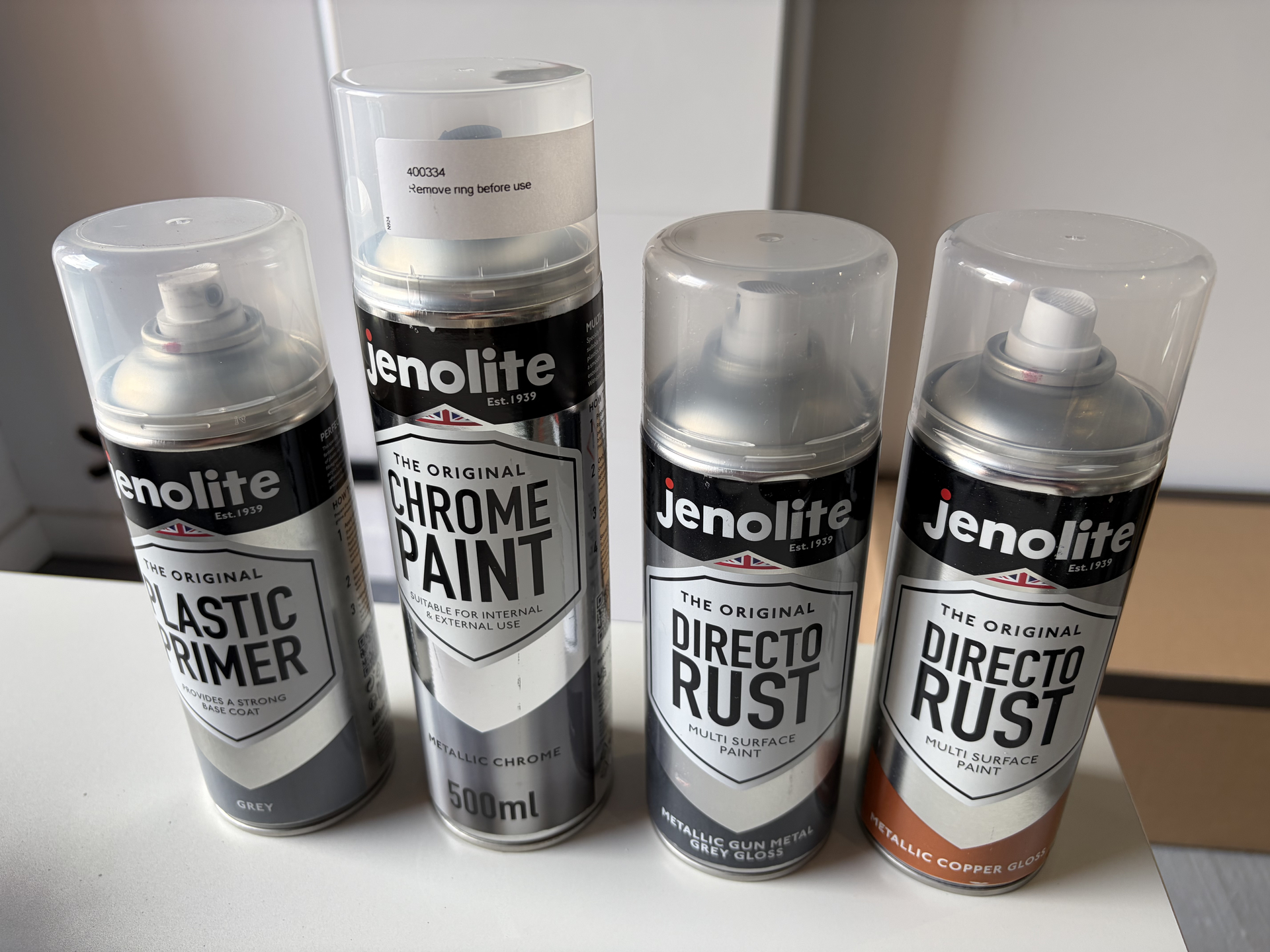
So first things first, starting with spraying up some of the cyclotron parts, starting with the cake as that’s the easiest part to remove. Going to be using mostly Jenolite paints for this:
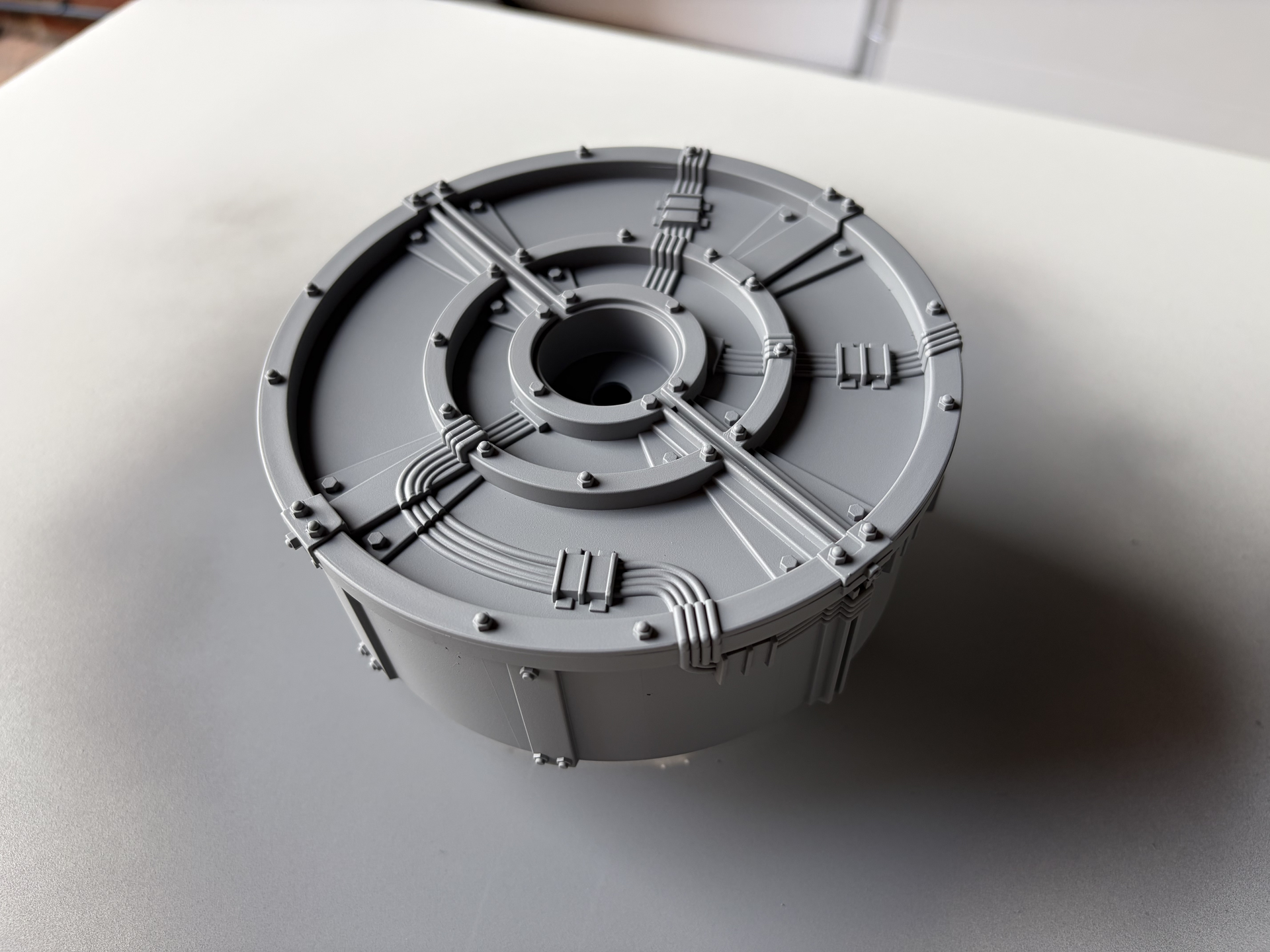
Even just with primer, the cake already looks ten times better!
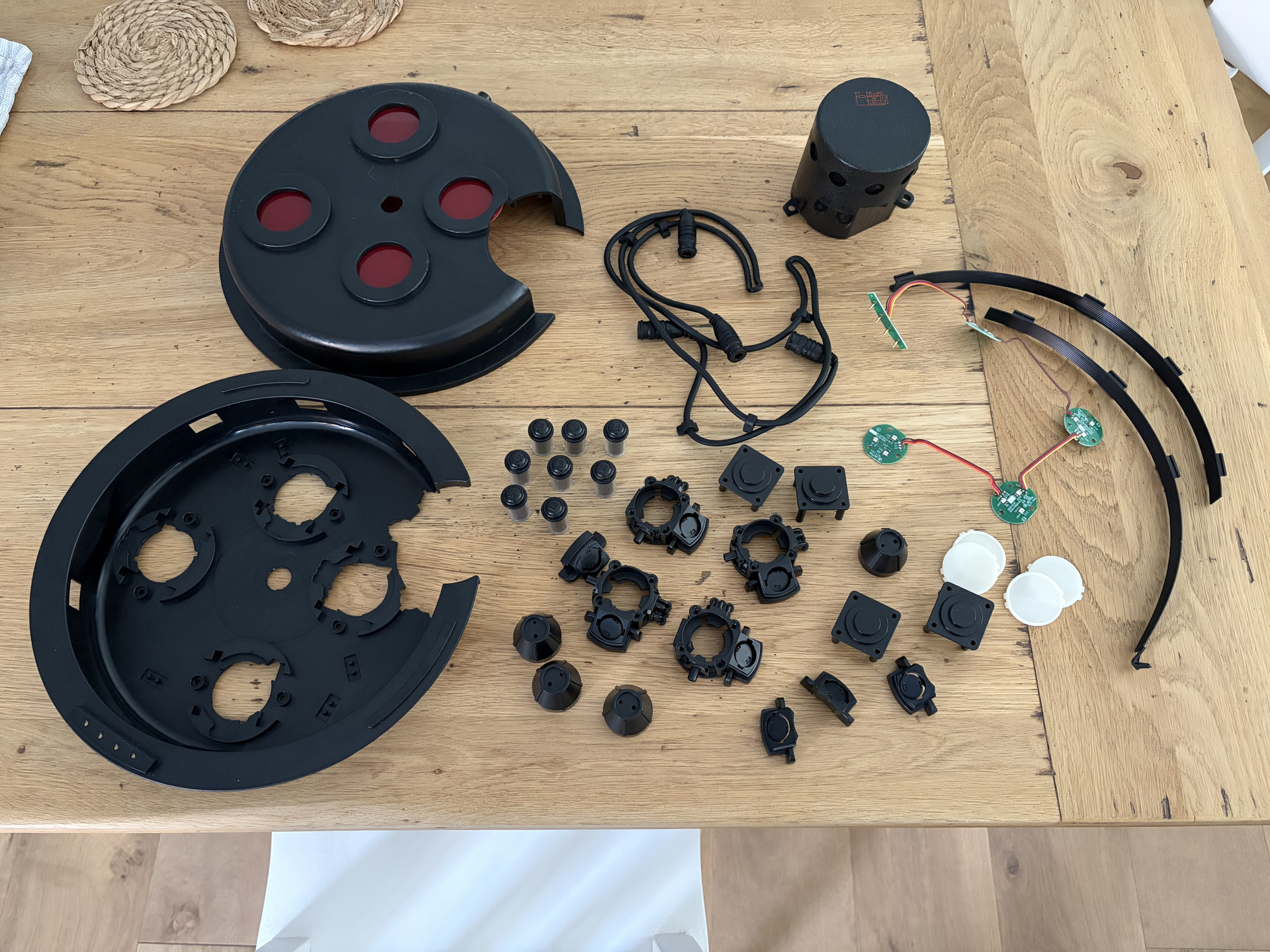
The cyclotron lid disassembled:
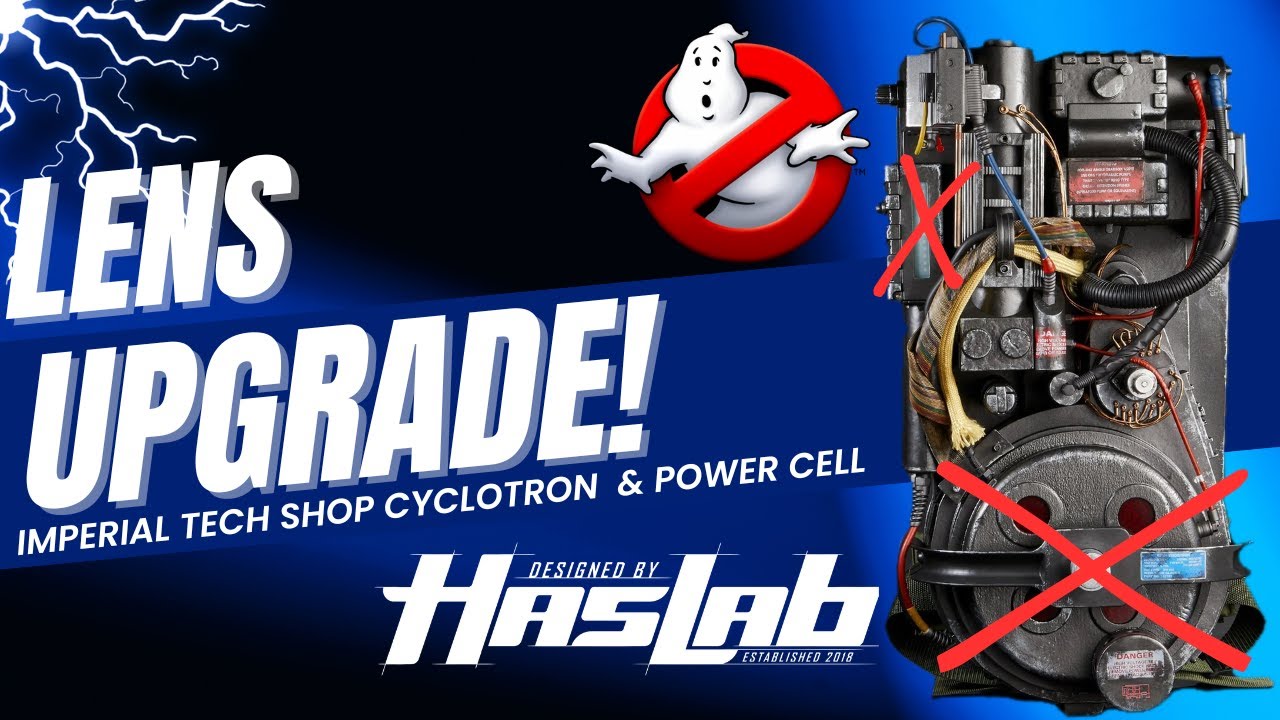
Update: if you need guidance on how to split the cyclotron lid, the video below is really good. I already had some blue plastic automotive trim pry/removal tools, so I used those and was able to pry it apart without damaging or stressing any of the plastic at all.
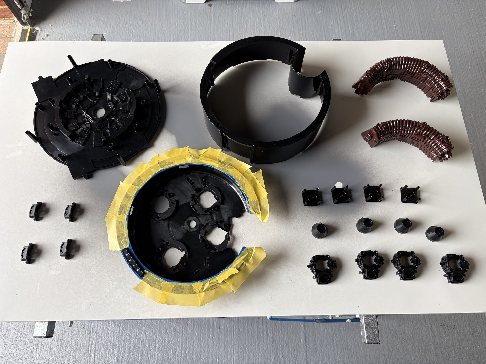
Ready for primer:
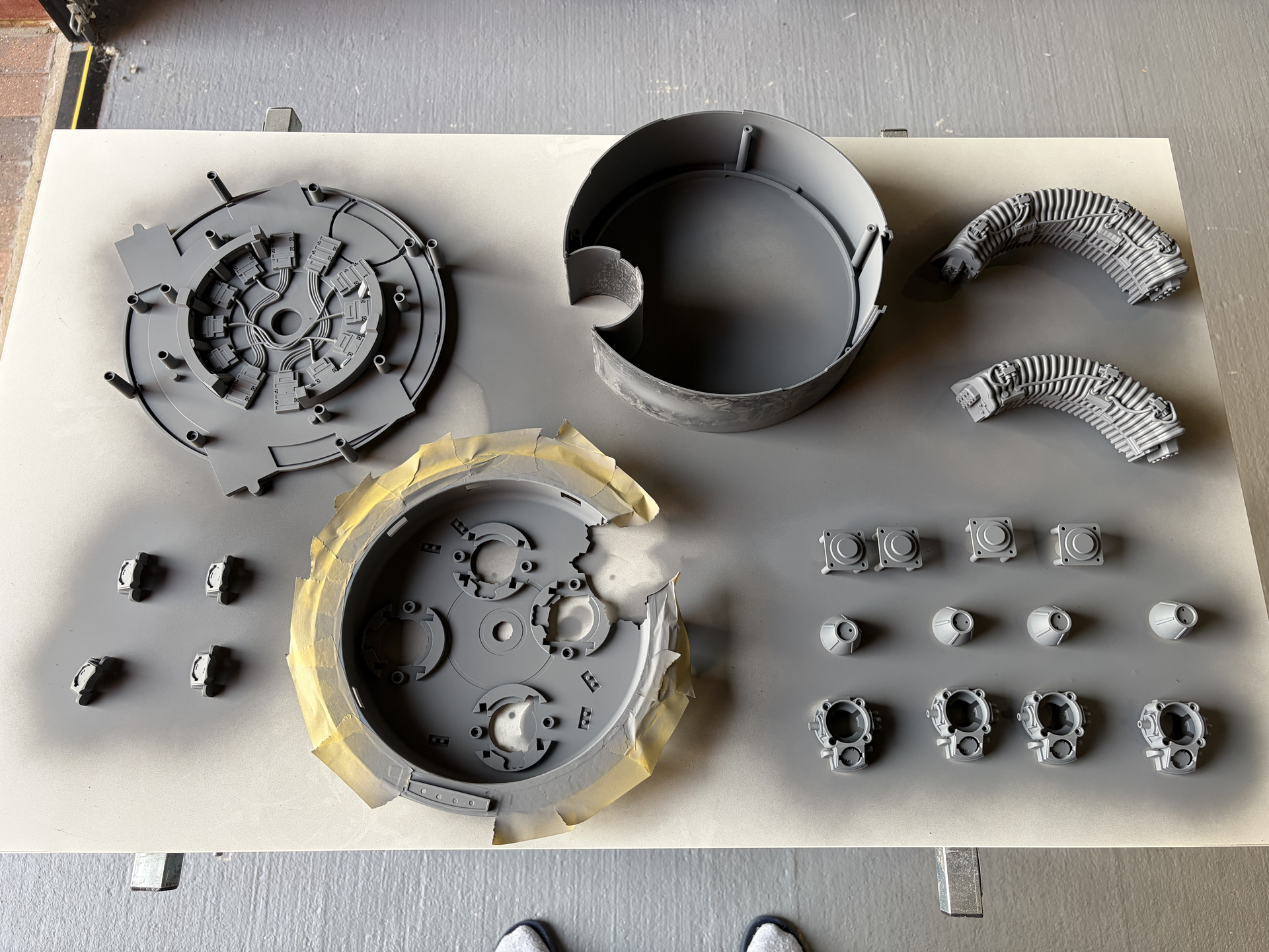
And after two coats of primer:
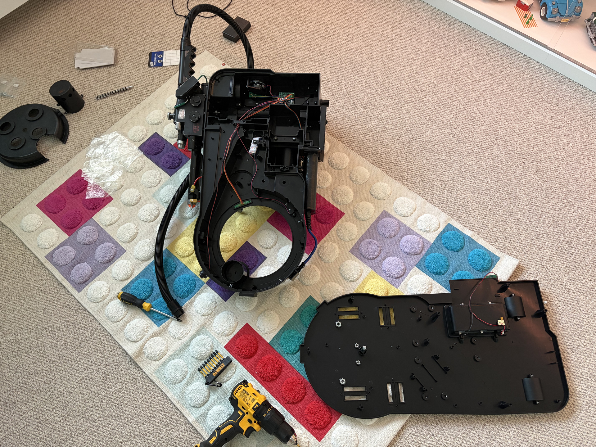
The pack with the motherboard removed to get to the inner cyclotron parts:
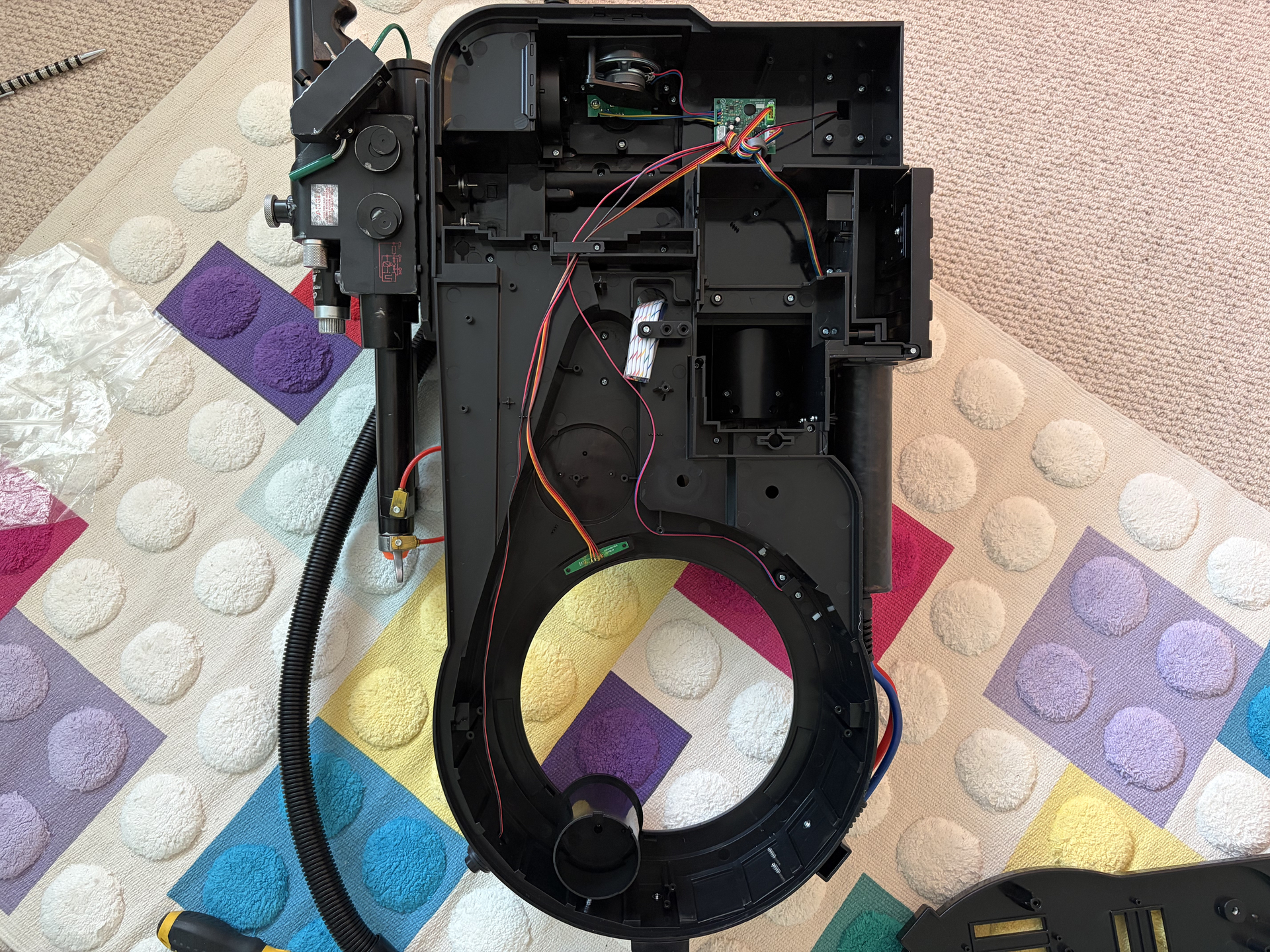
Close up of the inside of the pack, in case you want to see where the electronics are (side power type switch removed):
That’s where I’m up to for now as I’m only a few days into it, but I’ll be posting regular updates so check back soon, and if you have any questions, feel free to post them here!
3 Likes

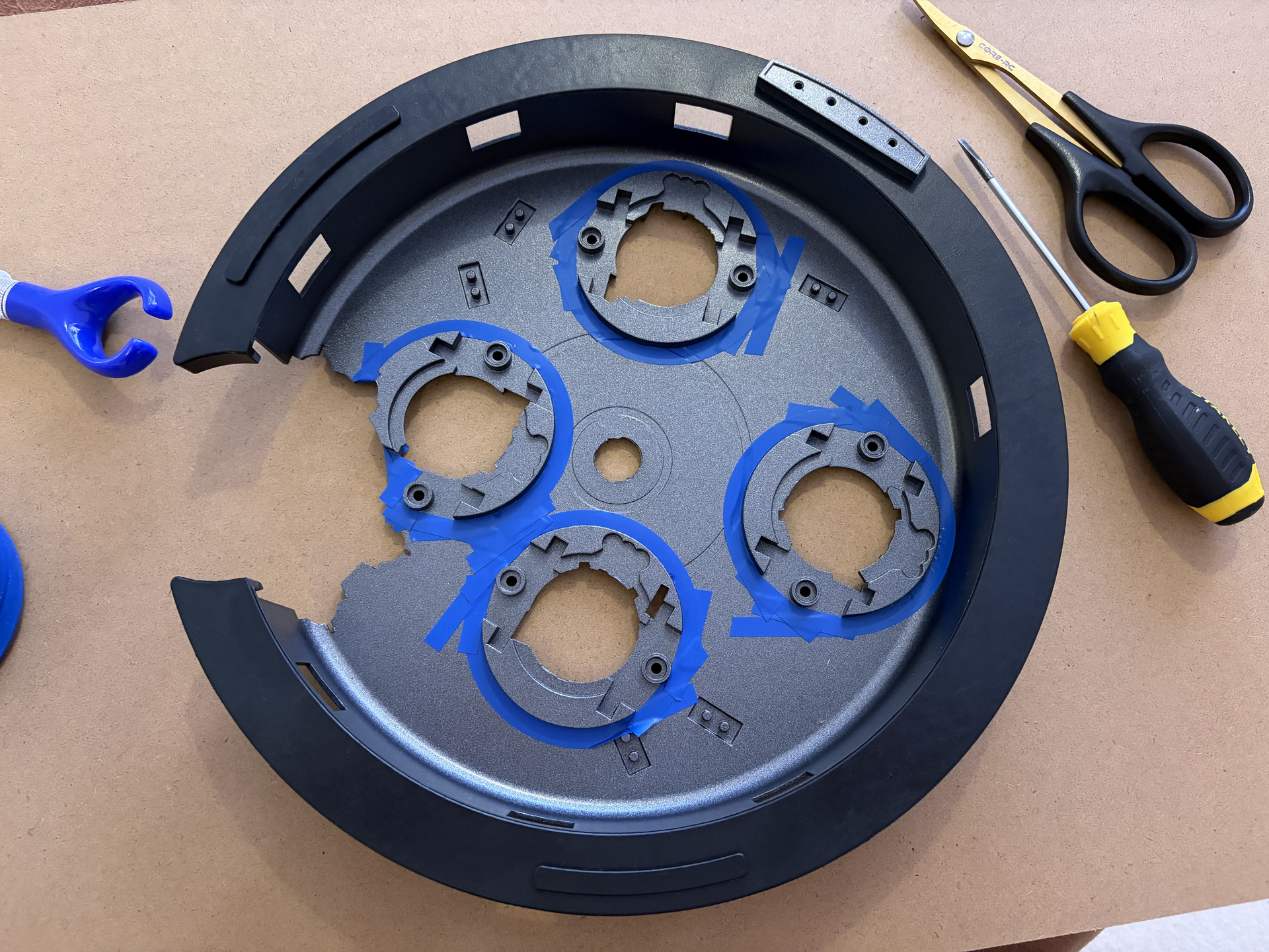
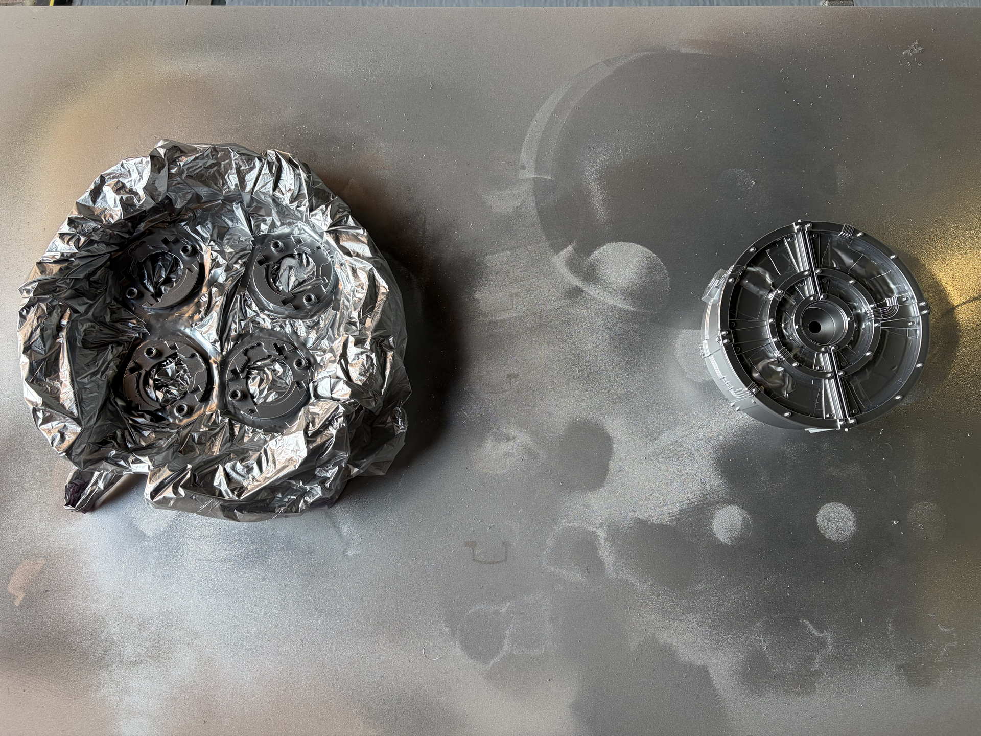
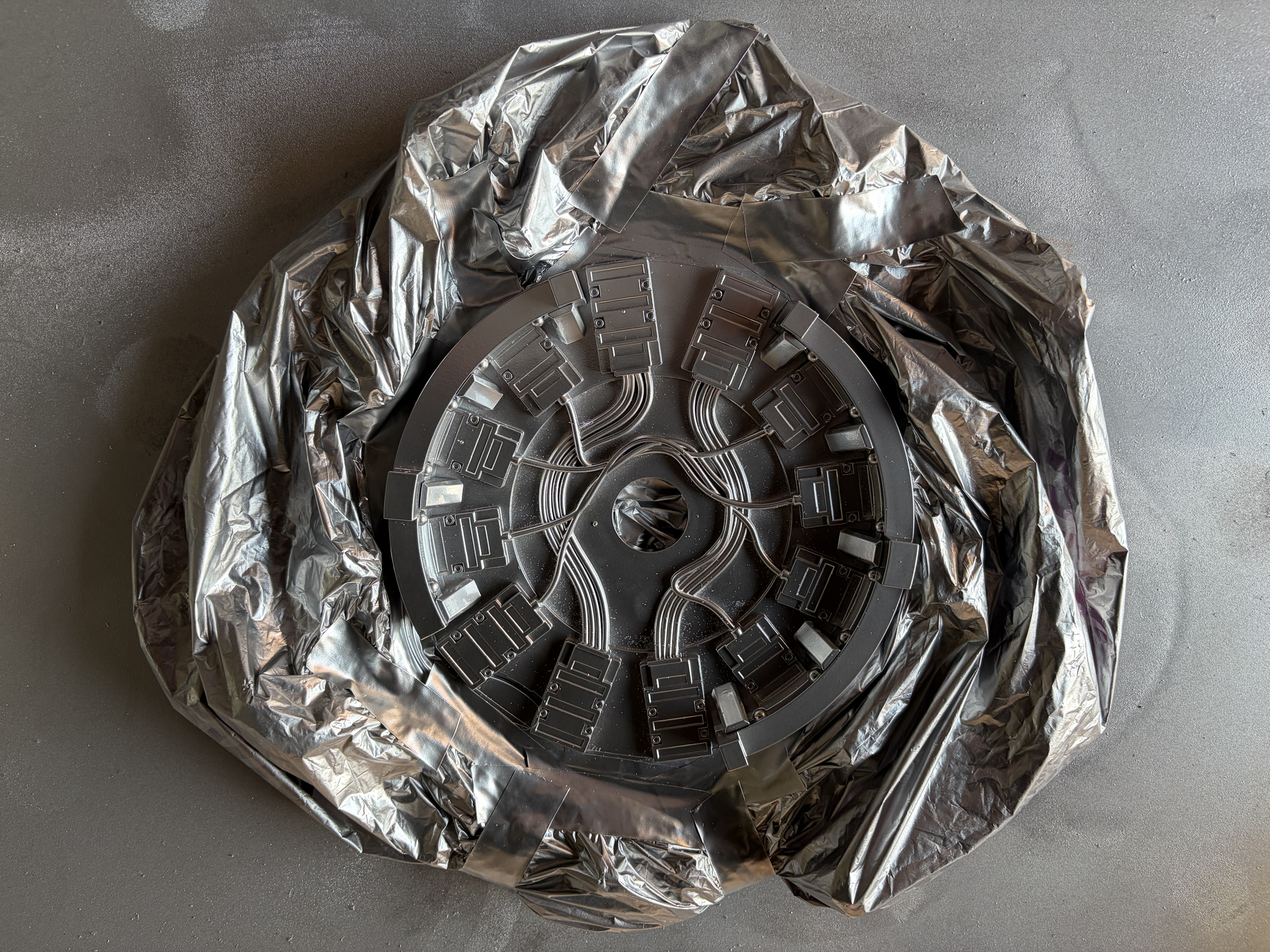
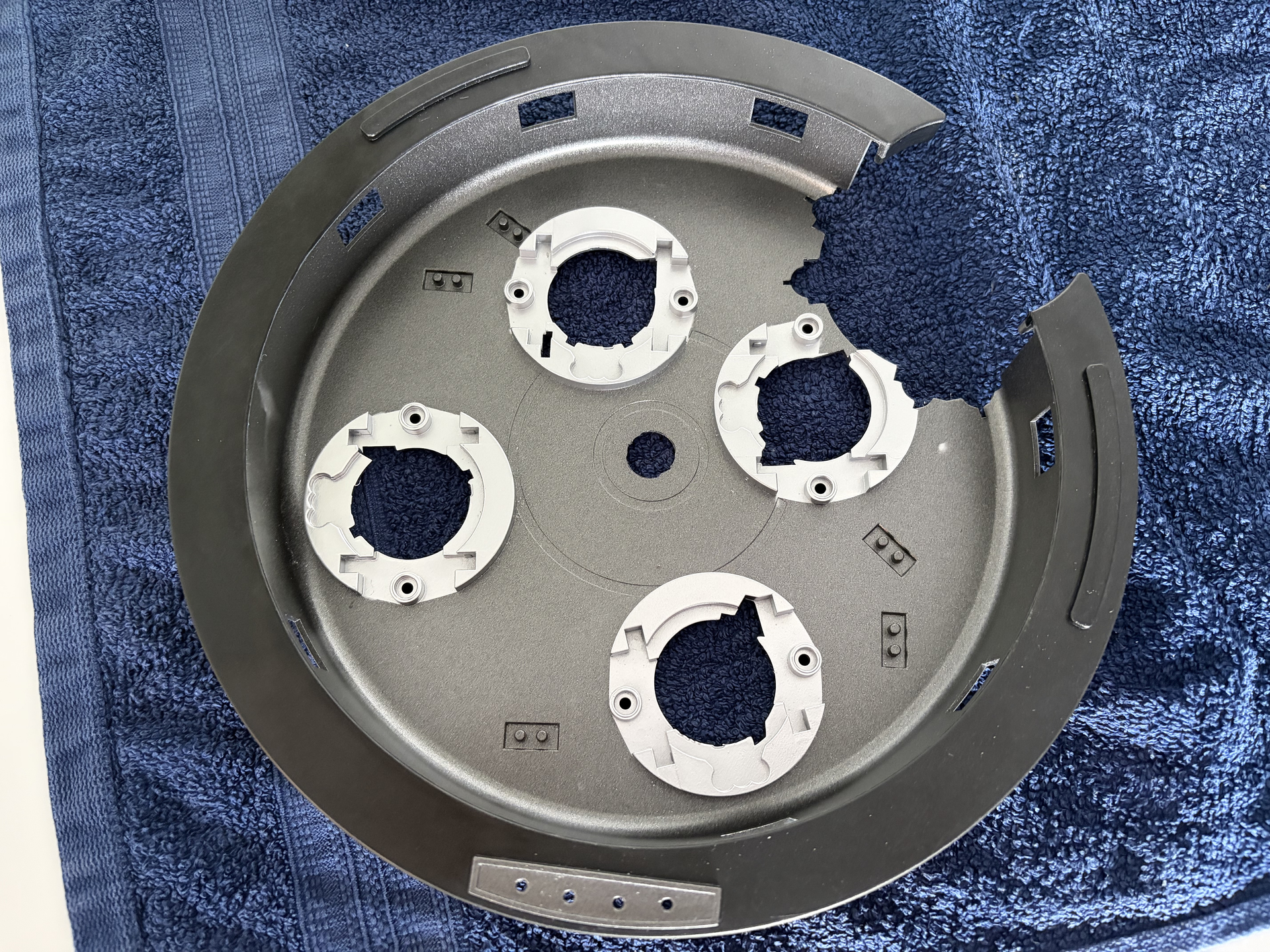
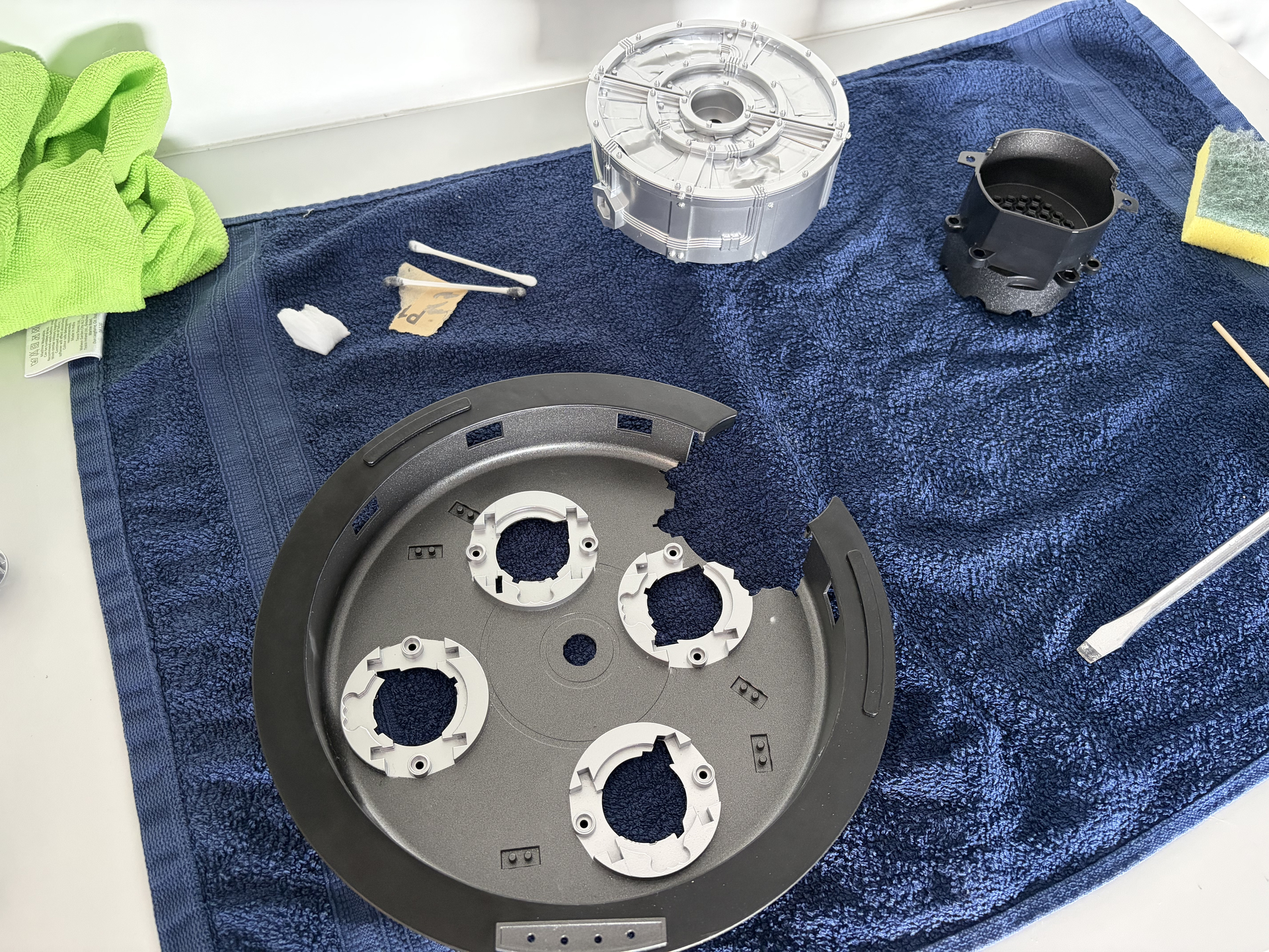
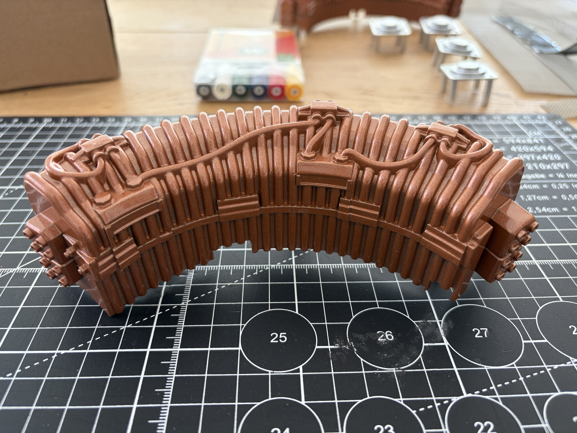
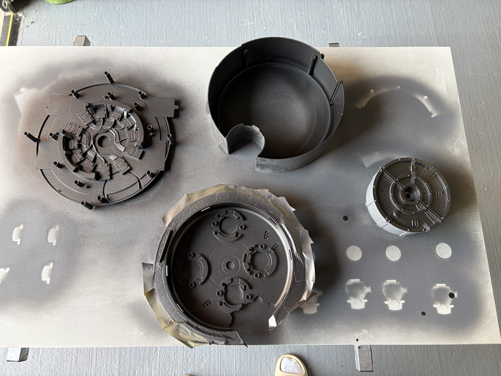
Some more painting today, this time the base colour for the inner cyclotron enclosure. I think ‘screen accurate’ is black, but I wanted to create more depth so I went with Jenolite Metallic Gun Metal Grey, which I’m really pleased with:

I’m now going to let this cure properly for at least three days before I start masking up for the chrome/silver accent parts.

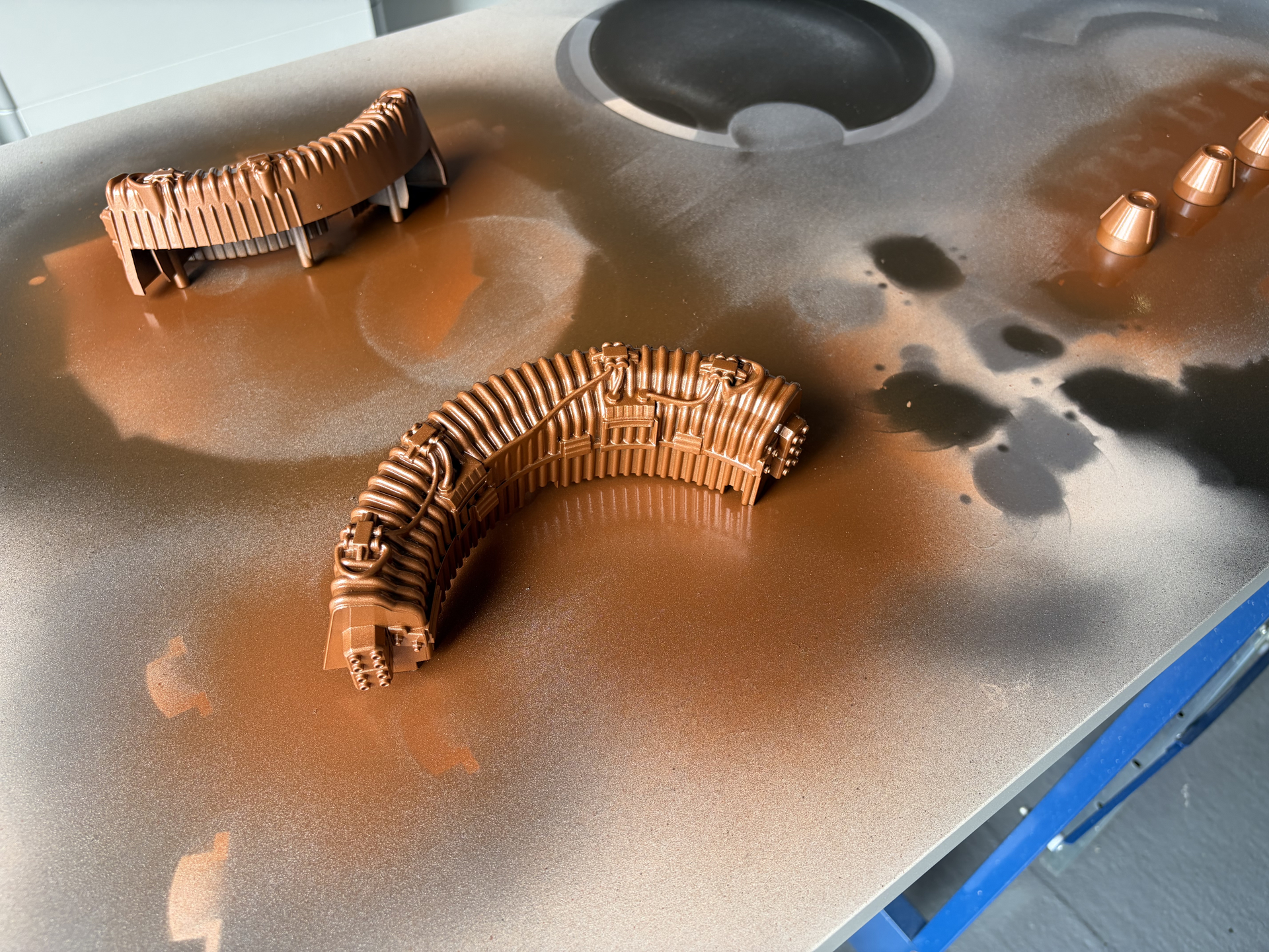
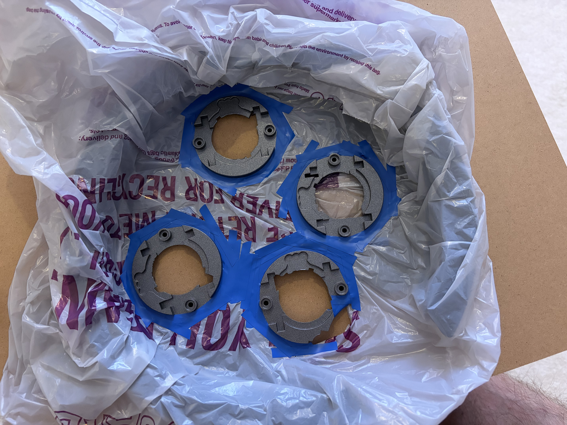
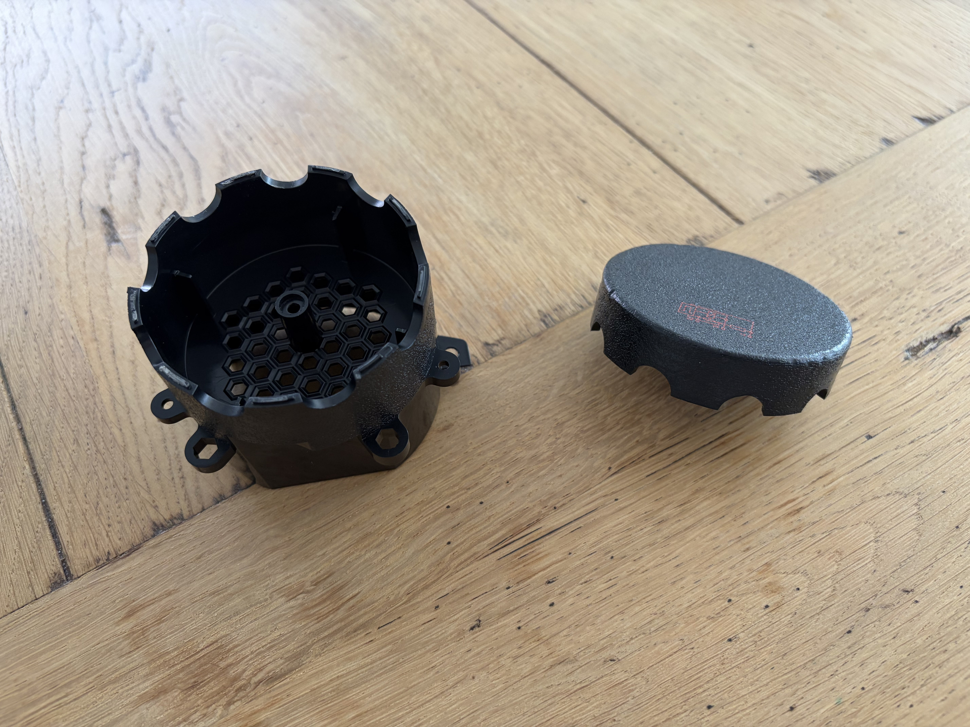
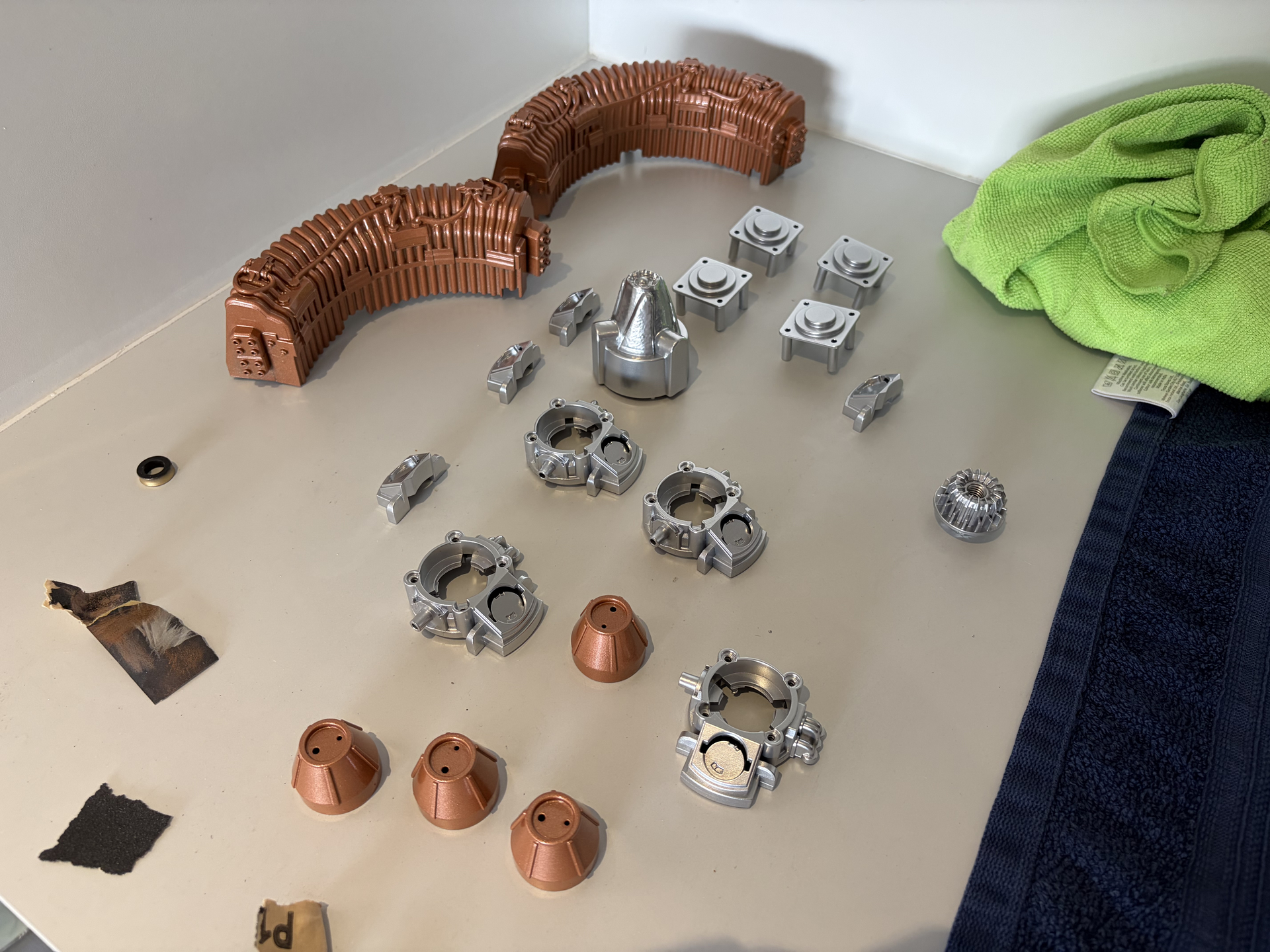
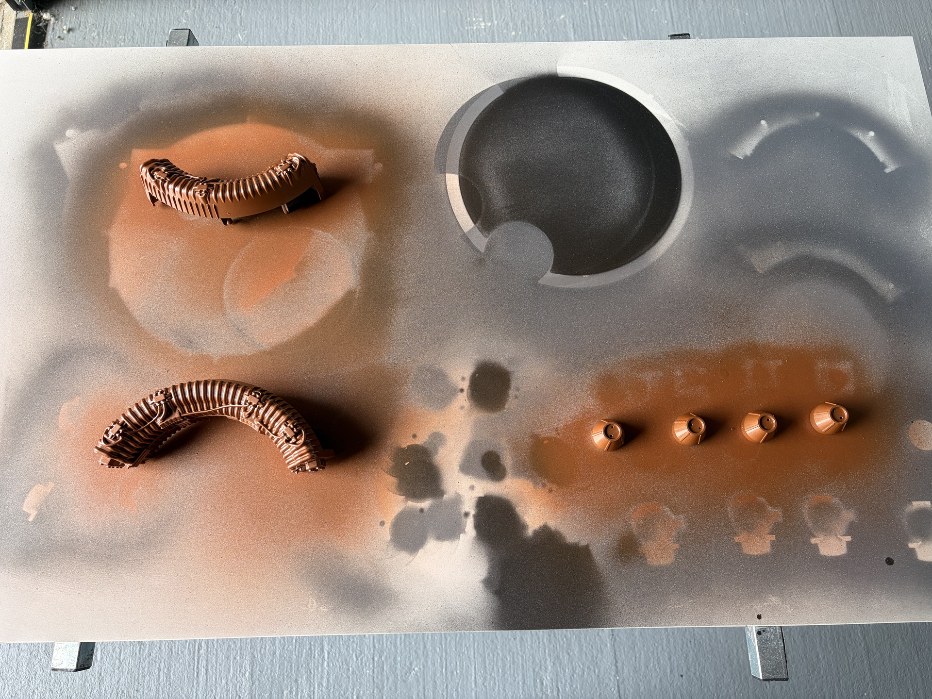
Also used the Jenolite Metallic Copper on these parts:

4 Likes

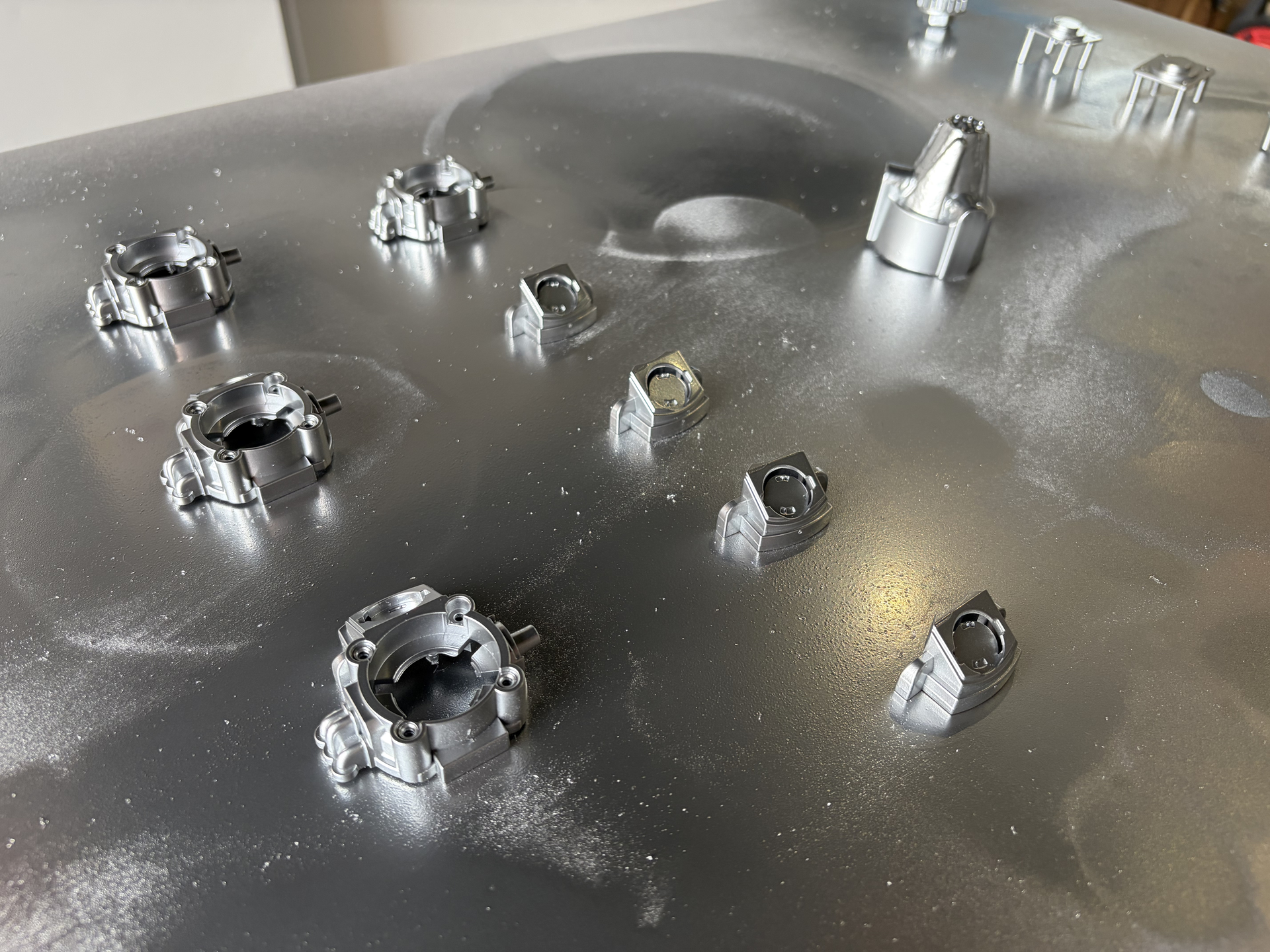
And some more painting today, this time some of the silver/chrome accent pieces using the Jenolite Metallic Chrome paint. This paint is excellent! Exactly the finish I was looking for. It’s definitely not proper ‘chrome’, more like a shiny bright silver, like anodised aluminium or stainless steel, a bit like the knobs that come on the Hasbro 1984/Spengler wand, which is exactly what I wanted. I think when everything is reassembled, you’d have trouble telling they weren’t real metal.

3 Likes

Next up, the tear down of the body shell and starting to fit the upgraded hardware.

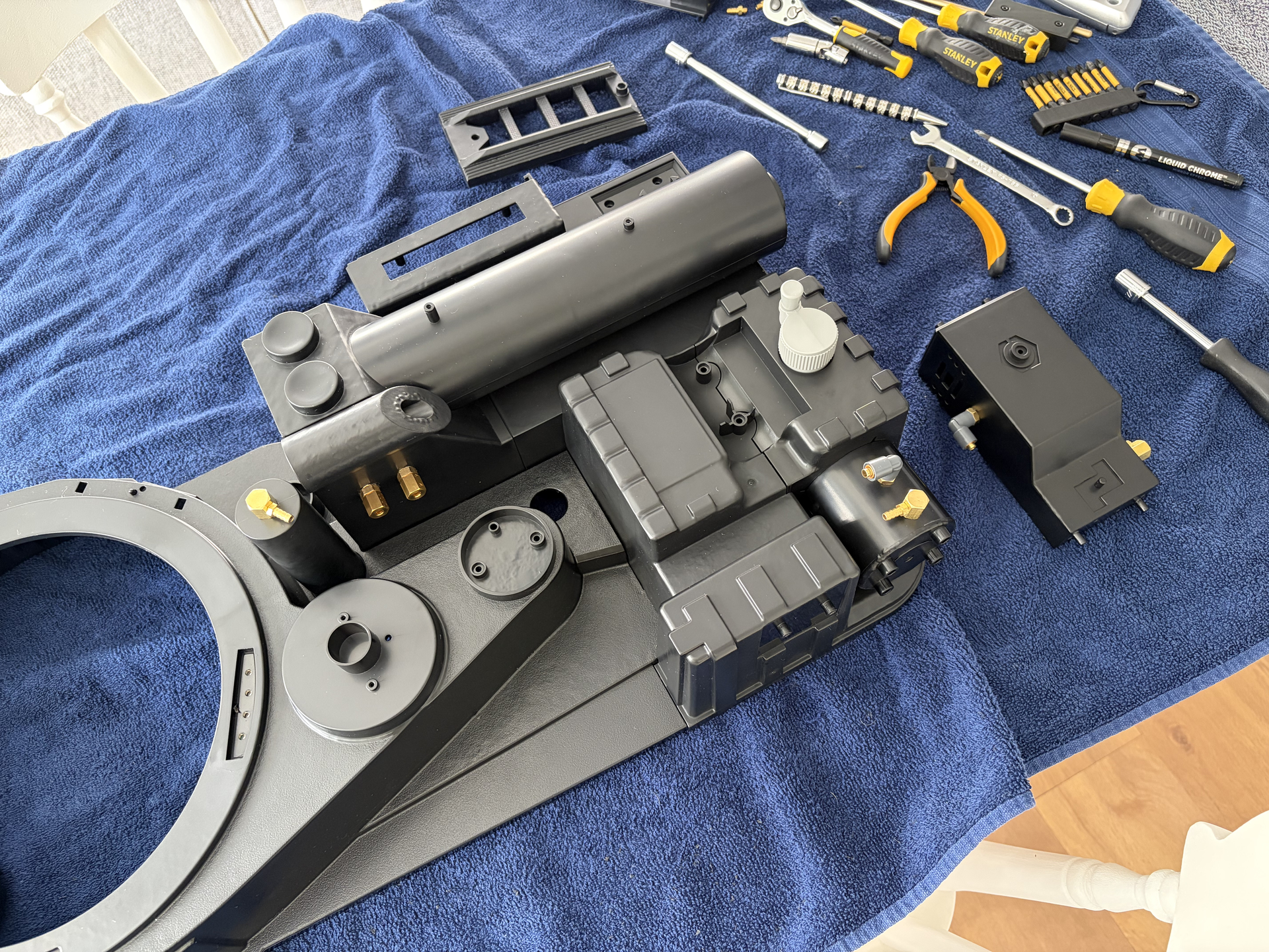
First, the parts that have already arrived, plus some that have already been removed, and some that I had left over from the Spirit pack two years ago:

A quick ‘before’ shot with the original rubber fittings and hoses:

After about an hour, the shell stripped down with most of the important parts removed. Because there are a lot of screws etc, I’ve been bagging up each main part:

A couple of hours later, all the brass elbows and legris were fitted. Bit of a pain as the largest drill bit I had was 8mm, but I think you need 9mm, so I had to keep widening the holes. A bit of trial and error, but got there in the end, and already these make a huge difference:

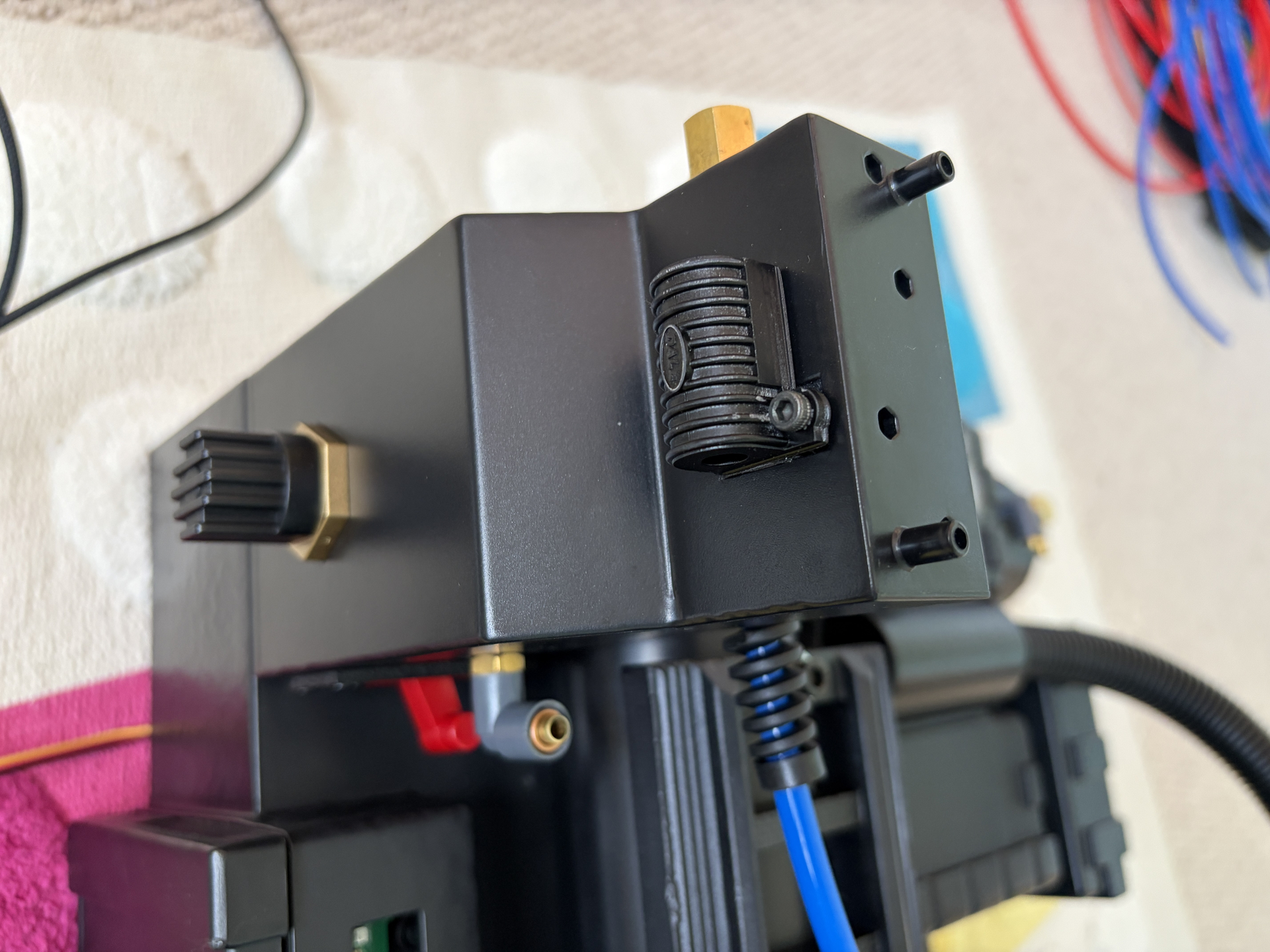
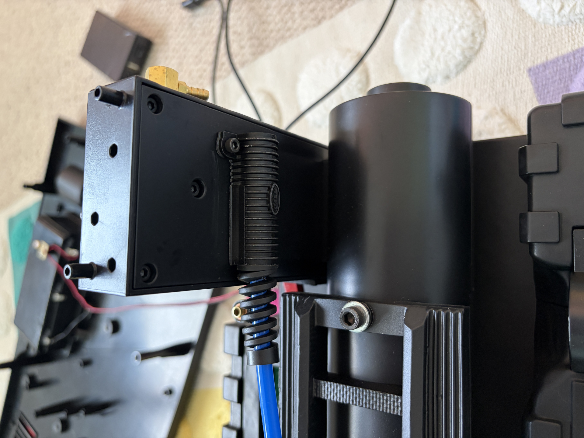
A couple of small things I noticed: even though Hasbro have badged this as a ‘1984’ pack, there are actually a couple of parts that were carried over from the Haslab Afterlife pack that aren’t technically accurate to the 84 film. First, the pack is supplied using rubber strain reliefs for the 6mm red and blue hoses, which is accurate for the Afterlife pack, but the 84 packs used small pieces of thin diameter splitless loom. I have replacements for both, but I’m trying to decide which I prefer. Second, the pack is supplied with the brass elbow on the top of the ion arm connecting to the end cap, but again, this is only accurate to the Afterlife pack. In the 84 packs, it connects further back. I actually positioned my following this.

3 Likes

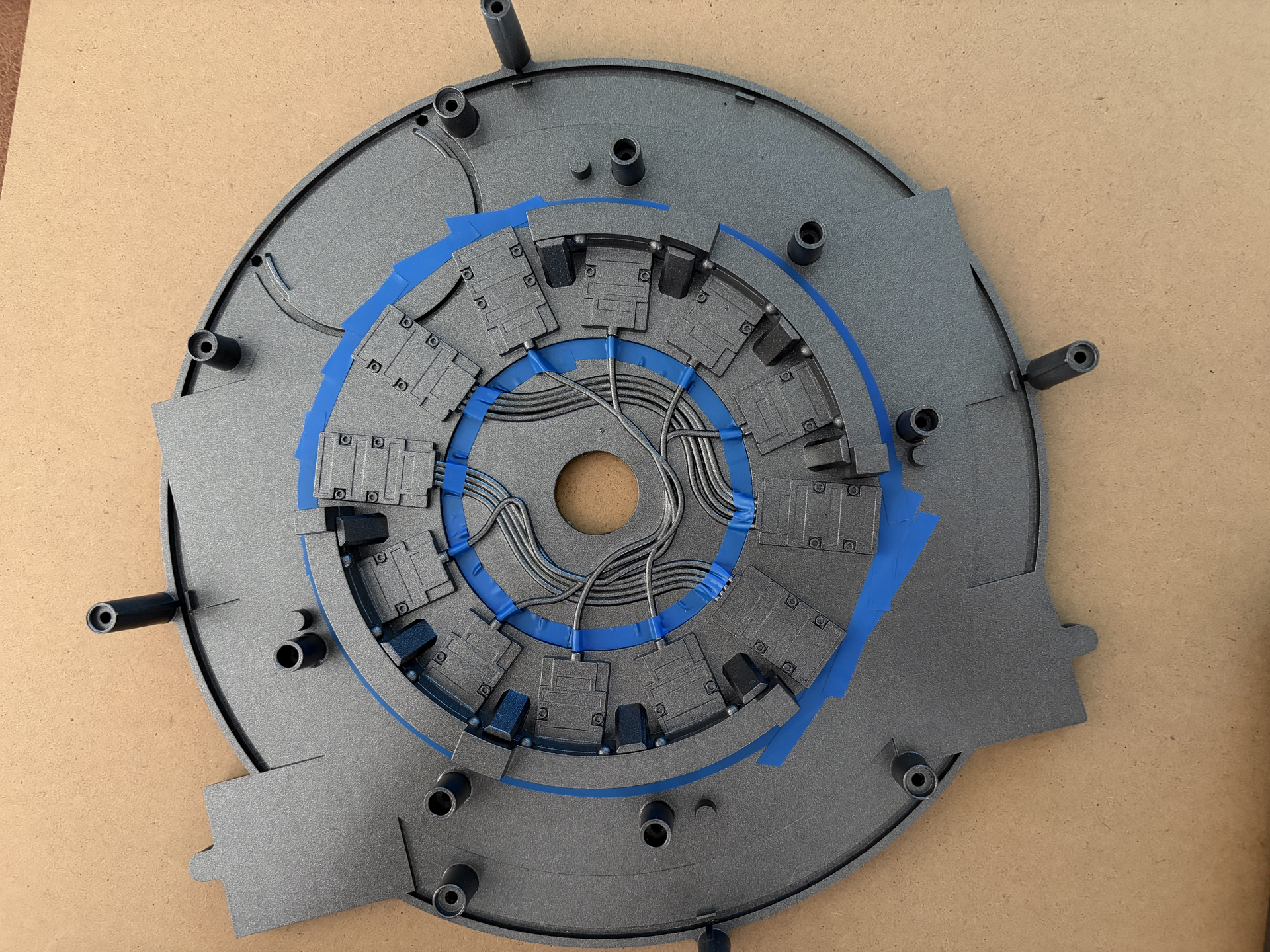
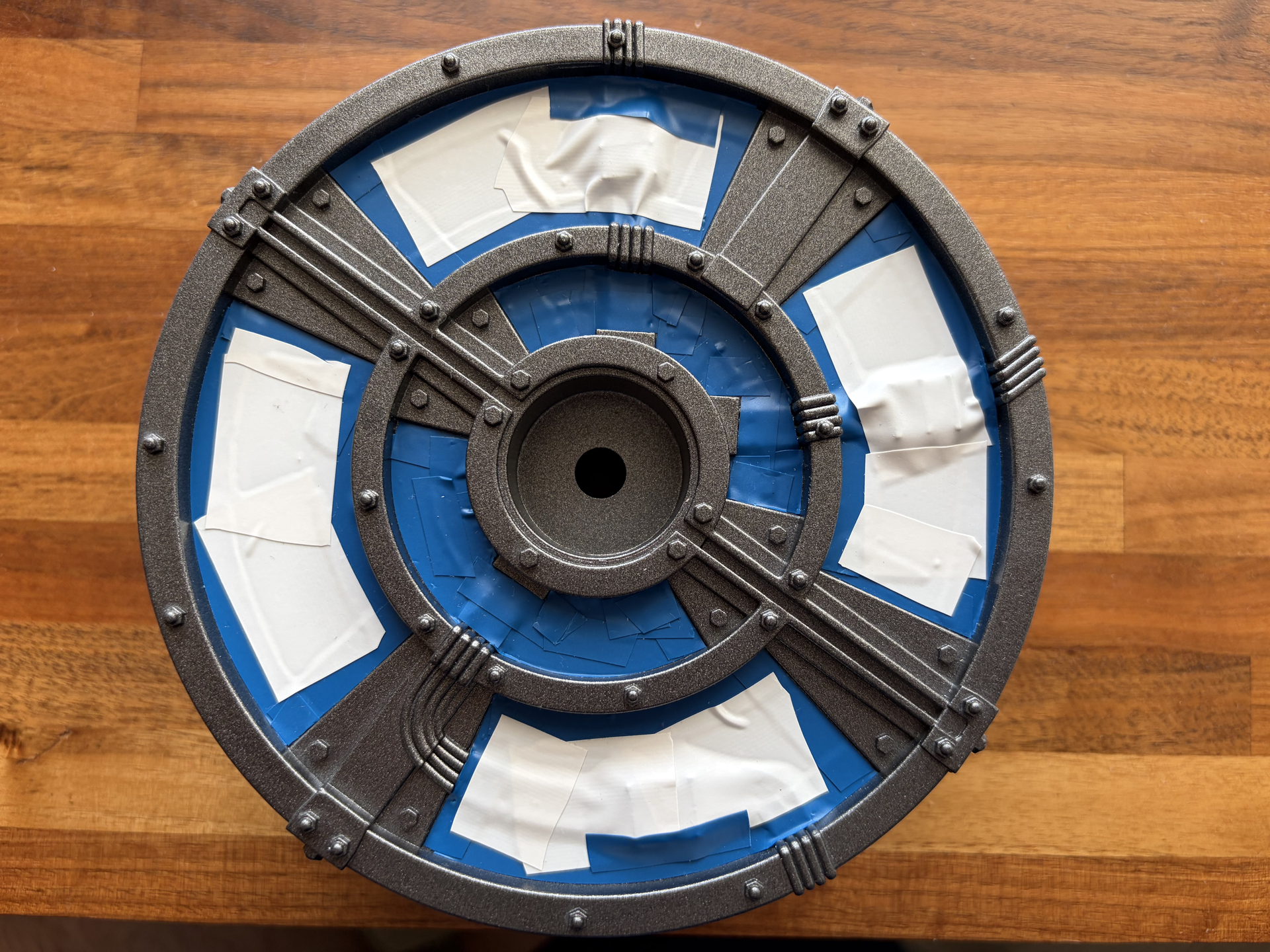
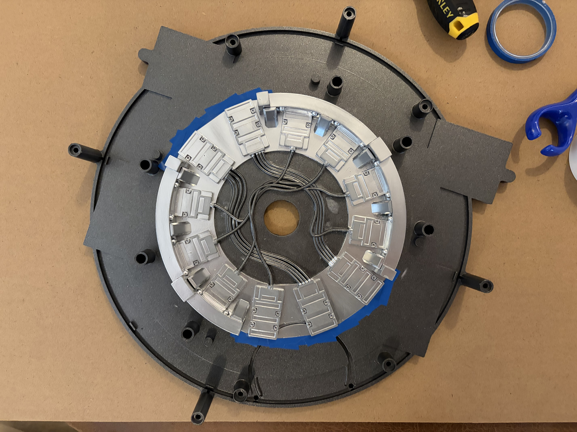
Back to spray painting, and now it’s time to mask up the areas that will be getting the silver/chrome treatment. I’m not going to lie, this was fiddly and time-consuming work, but it should hopefully be worth it if it all turns out okay.

First the inner cyclotron base/back panel:

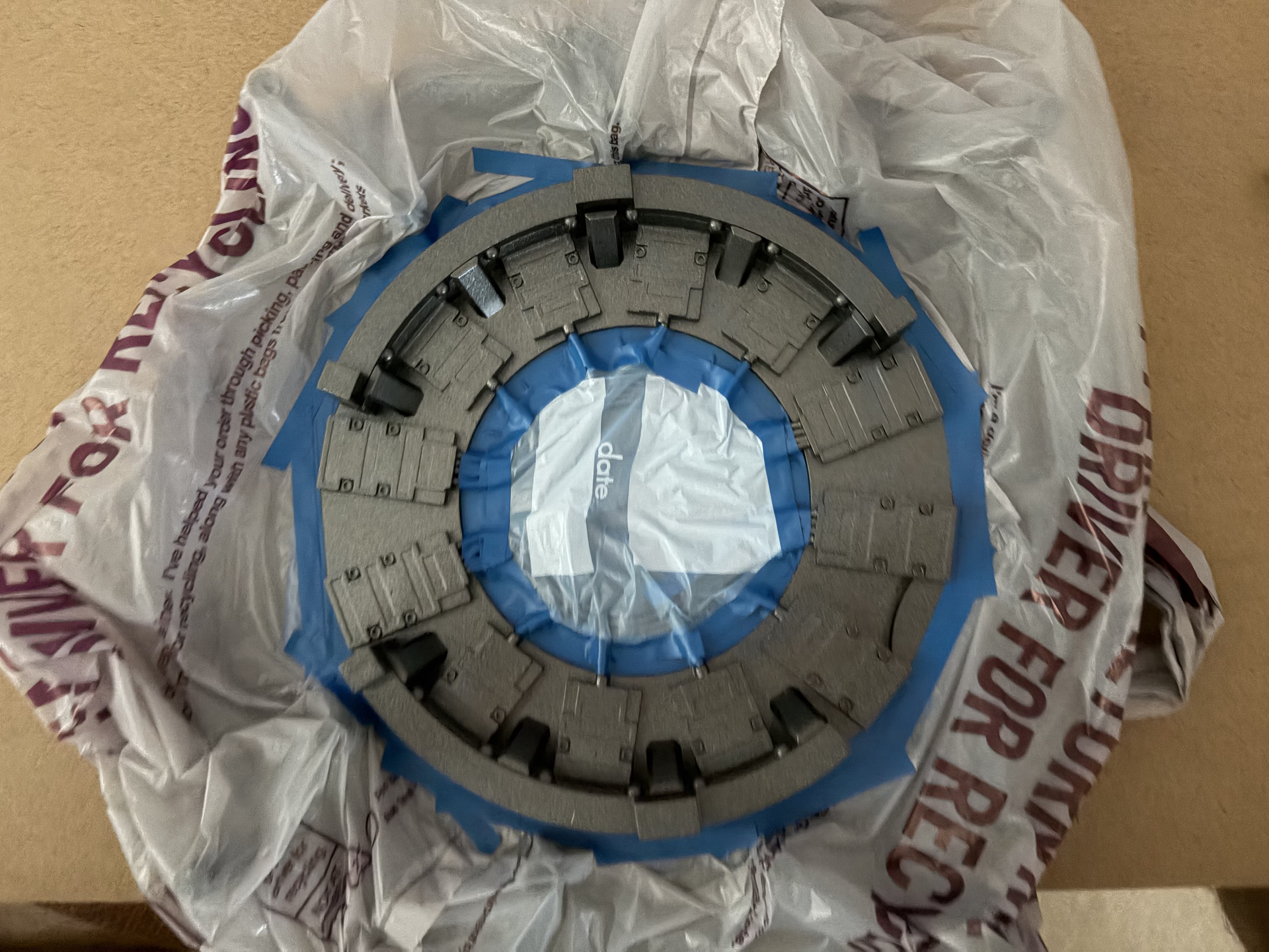
Then the cyclotron lid and cake:

The trouble with detailed masking work like this is you have an anxious wait of at least 24 hours until the paint has dried enough to be able to peel back the masking tape and see if you’ve made any mistakes or if there’s been any paint overspray.

1 Like

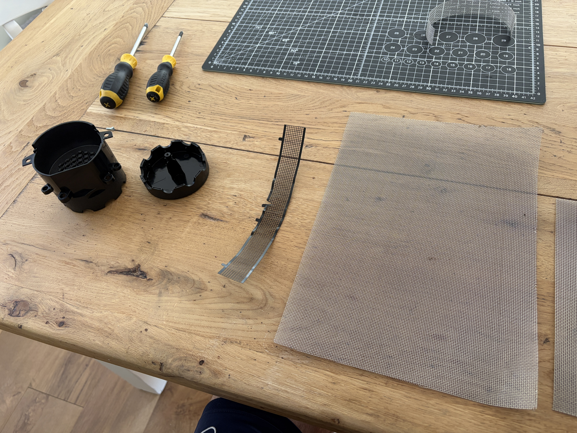
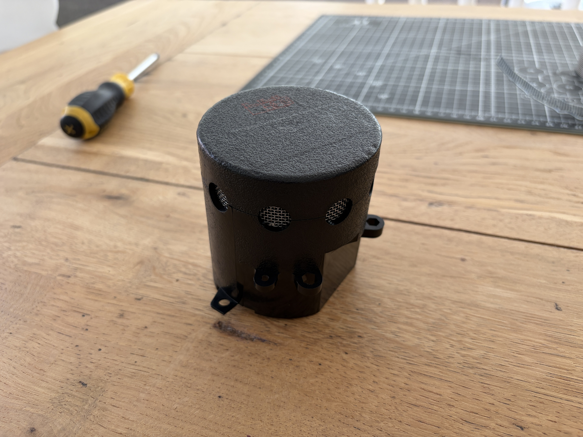
While I wait for the paint to dry, I managed to open the n-filter. I don’t really like the original black mesh inside, so I want to replace this with some proper metal mesh that I have left over from the Spirit pack.

It’s a bit deceptive though, as if you look at the n-filter from the bottom, there’s a single screw in the middle. This does hold the cap, but so does some factory glue as well, so here’s how to separate them:

  1. Apply some mild heat to the join that runs through the middle of the circular vent holes. A hairdryer or heat gun will be fine. Hot enough to soften the glue, not so hot it warps the plastic.
  2. Push a long-ish screwdriver into one of the vent holes, pushing the black mesh out of the way as you do it.
  3. Wiggle the screwdriver around and downwards until it rests on something solid, then push the screwdriver up to pry the end cap off.

Not too hard that it bends the plastic, just a firm steady push, and it will pop off so be prepared to catch it.

Now I can install the proper metal mesh inside it and then use the original single screw to fix it back together.

2 Likes

Okay quick update on the painted parts. Overall good progress, though with a couple of hiccups along the way.

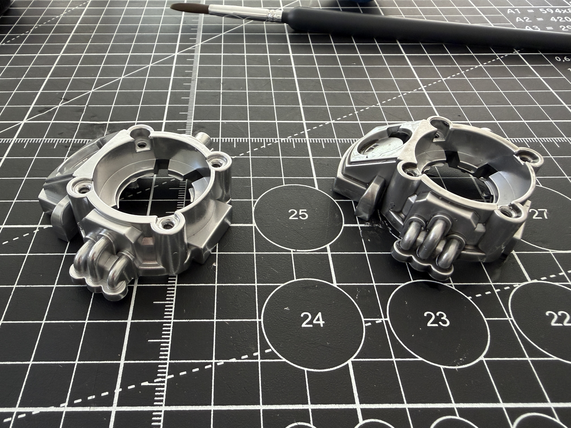
First the inner cyclotron back panel. Unfortunately, I got a bit of paint overspray/bleed through the masking tape on the inner dark grey area, which is annoying as I wanted that part to be dark grey, but it’s not the end of the world as I have a plan B which is just to re-mask the outer ring and then respray the whole section the chrome/silver, so it will all be that colour. Here’s how it first turned out. You can see the part where I unsuccessfully tried to correct the overspray in the centre-right of the dark grey inner ring:

Then masked up and resprayed:

Then with the masking removed. Looks a lot better!

Now for the inner cyclotron lid, and I’m really pleased with how this turned out:

There’s a small silver overspray mark on the right-hand side, but hopefully the black cables will cover that when I refit them, or failing that I have some similar Tamiya Gun Metal Grey brush paint that I may try touching it up with. There’s also a slight silver overspray to the left on the inside wall, which was frustrating at first but then I realised it will be covered by the rainbow ribbon cable, so that worked out okay.

It’s just really hard to do detailed masking like this without there being some paint that gets through the masking, no matter how hard you try.

Then below with the cyclotron cake and n-filter in the background. I haven’t removed the masking from the top of the cake yet, just because I want to give the chrome/silver plenty of time to dry, as it will need more handling than the other parts and it’s quite a soft paint so I don’t want to get any finger prints in it. I also masked up and sprayed the inside mesh part of the bottom of the n-filter, just so it matched with the rest of the inner cyclotron lid (not very noticeable in this photo but a nice touch and worth the extra effort):

Even without the masking tape removed from the top of the cake, it looks so good in the silver/chrome. If there are any issue with overspray/bleed when I remove that, I won’t be unhappy to just spray it all the chrome/silver.

And below all the other painted parts waiting to be reassembled. I’m really happy with how it’s all going:

I’m probably going to give everything a few more days just to properly cure, but then it will be a case of reassembling everything and also doing more detail work for things like the colour wires and other silver parts, using a few Molotow pens that I have.

1 Like

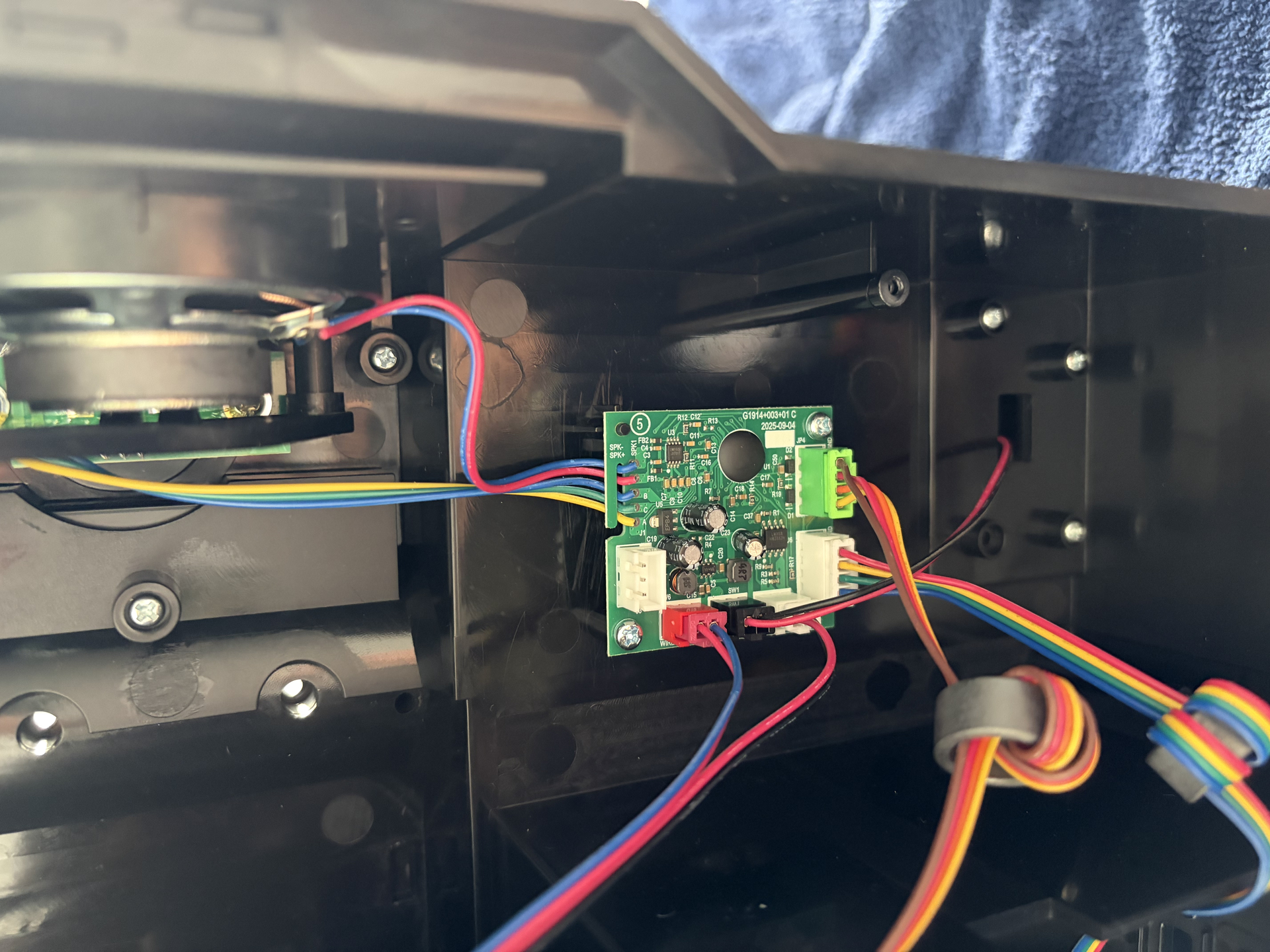
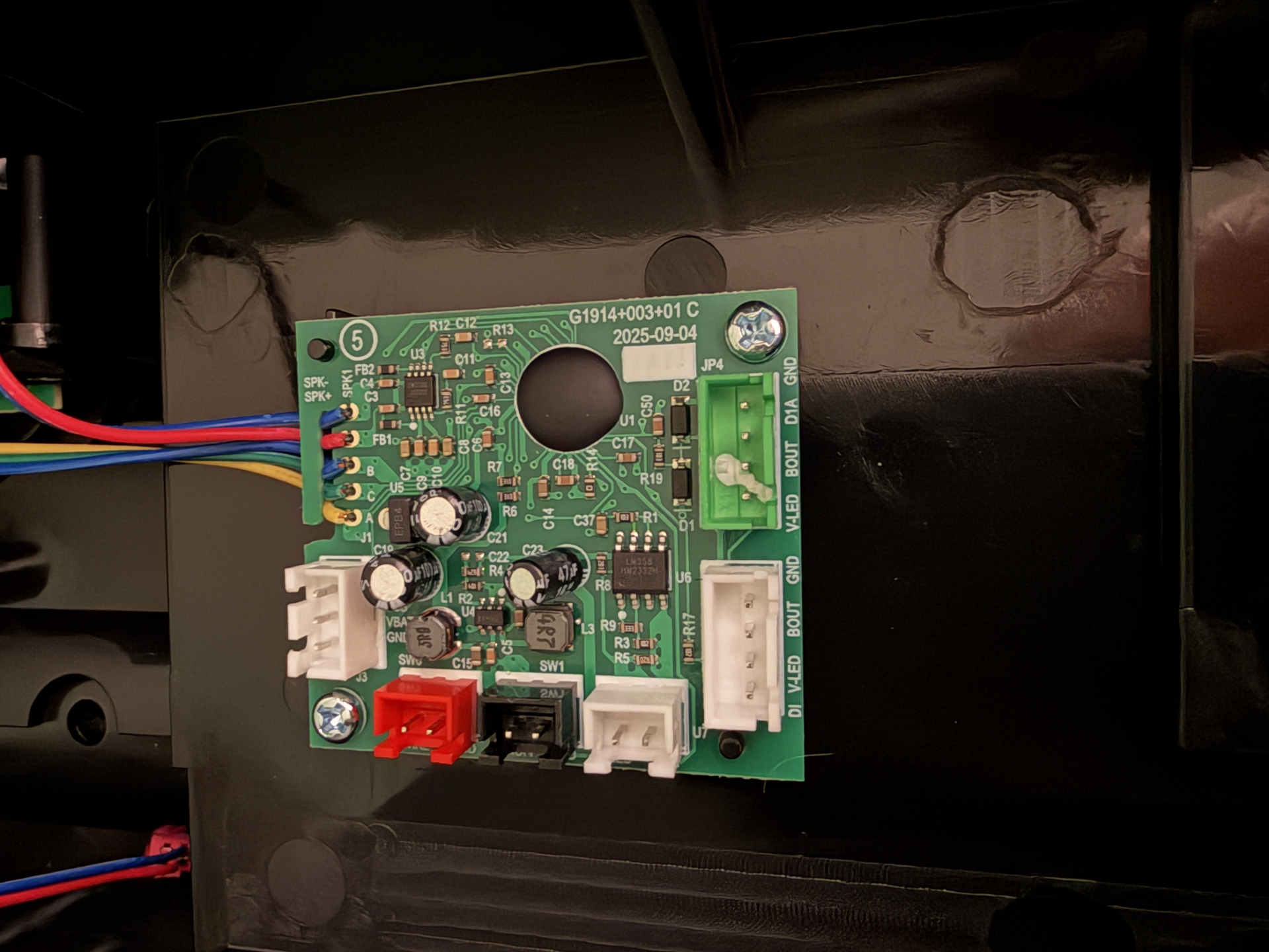
Looking sharp! I wish I had painting/weathering skills. Would you have a moment to take a picture of the 1984 mainboard for me if possible and post it? want to see what they changed for the ribbon/cyclotron cable and need to see which lines are which. ie where the green 4 pin connector connects to the board, want to see which lines are for 5v, ground, and data etc.

Yeah of course, do you mean the default green PCB that comes with the pack? If so then I actually took a photo of this before I started disassembling the pack, just so I had a reference for where everything goes. I think the only JST that has been disconnected was for the D-cell battery compartment that is moulded to the motherboard, as I needed to disconnect that to completely remove the motherboard:

Yep thats the part, but can you take a picture from the other side where that green ribbon cable connects to the green port on the board? the other side has markings on the board labeling which wire does what.

How’s this, with all the JSTs removed:

Another busy but productive weekend! First off I added the real metal mesh to the n-filter. I had a sheet left over from my Spirit pack two years ago, but you can pick this stuff up pretty cheap on Amazon, and it’s so thin you can cut it with scissors. In the middle is the original black mesh that came with the pack, which I used as a template to cut the new strip:

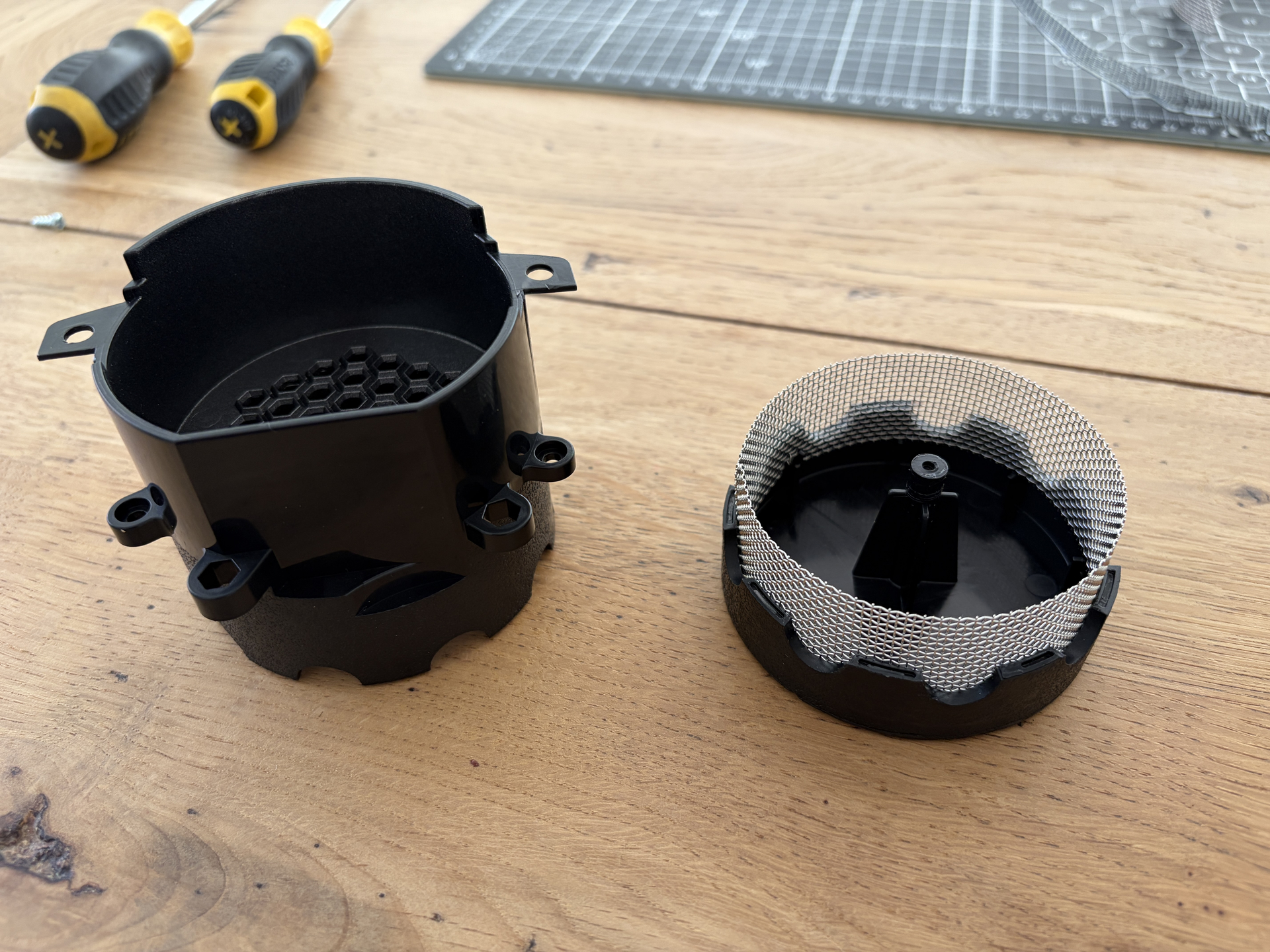
There are tabs within the n-filter that it just slots into and holds it in place, so you don’t even need to use glue:

Then I just used that single screw on the inside to fix it back together. Easy peasy! Looks so much better:

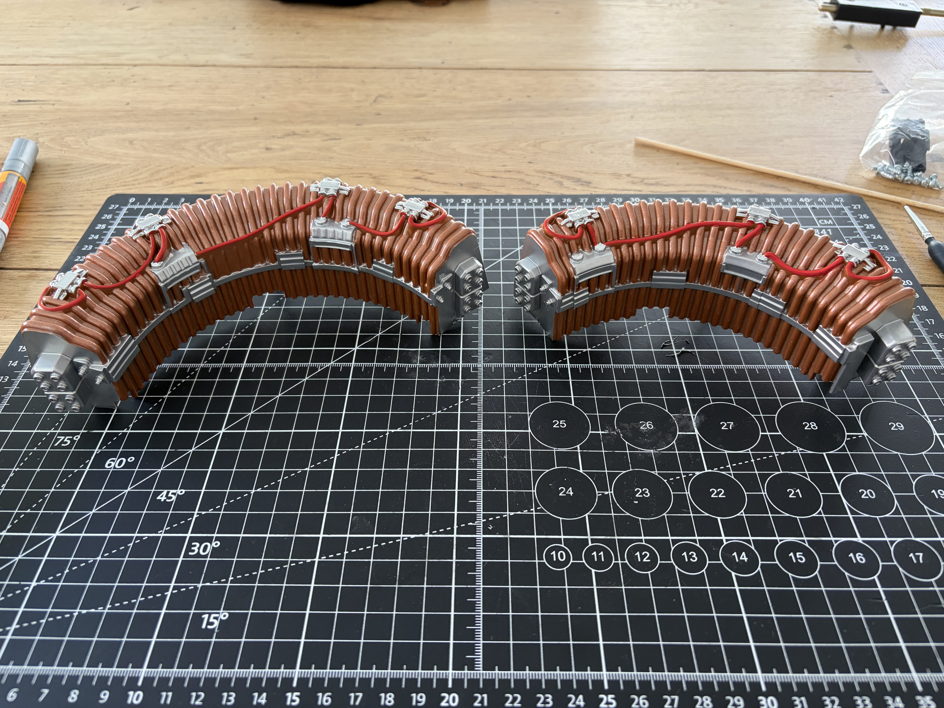
Next up was some detailing work on the copper ‘kidney’ pieces from the inner cyclotron. Before:

And after, using Molotow chrome, red and metallic silver paint pens:

I think I managed to get them pretty close to this reference photo. Next up it was time to work on the inside of the cyclotron lid. I tried some subtle ‘grime’ using a Vallejo wash, before on the left and after on the right:

But it came out looking a bit too ‘dirty’, so as I’m going for a more clean, fresh pack build, I washed this back a bit.

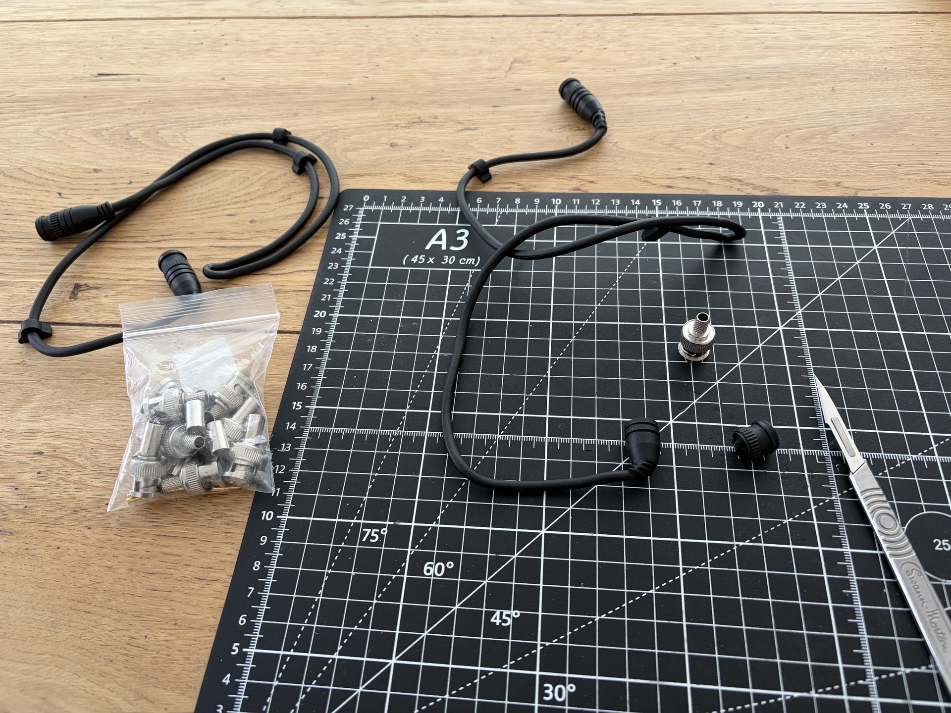
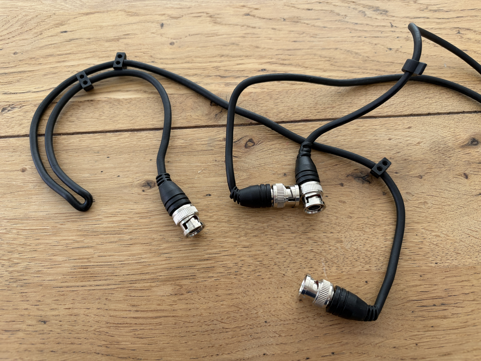
Next up was a simple but really effective mod for the black rubber cables that go inside the cyclotron lid. I got this pack of 10 real metal BNC connectors from Amazon for literally around £5. They look amazing and they’re pretty much identical to the ones they actually used in Afterlife.

Installing them was really easy. I used a scalpel blade to slice the ends off the original cables, then used a 5.5mm drill bit to drill holes into the remaining stubs for the metal BNC connectors to sit into. 5.5mm was the perfect size, as the connectors then just push in and are held tight enough with pressure that you don’t need to use glue. You could also use a 6mm bit if that’s all you have, you’ll just need to glue them in place:

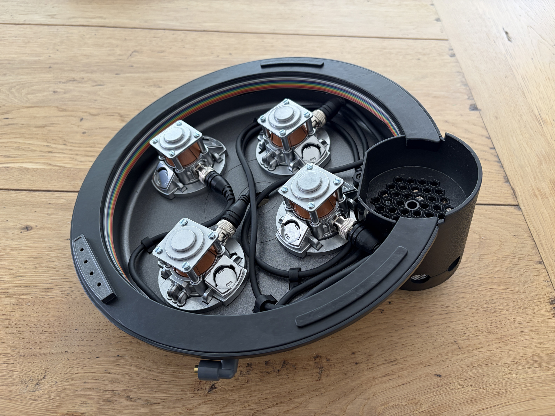
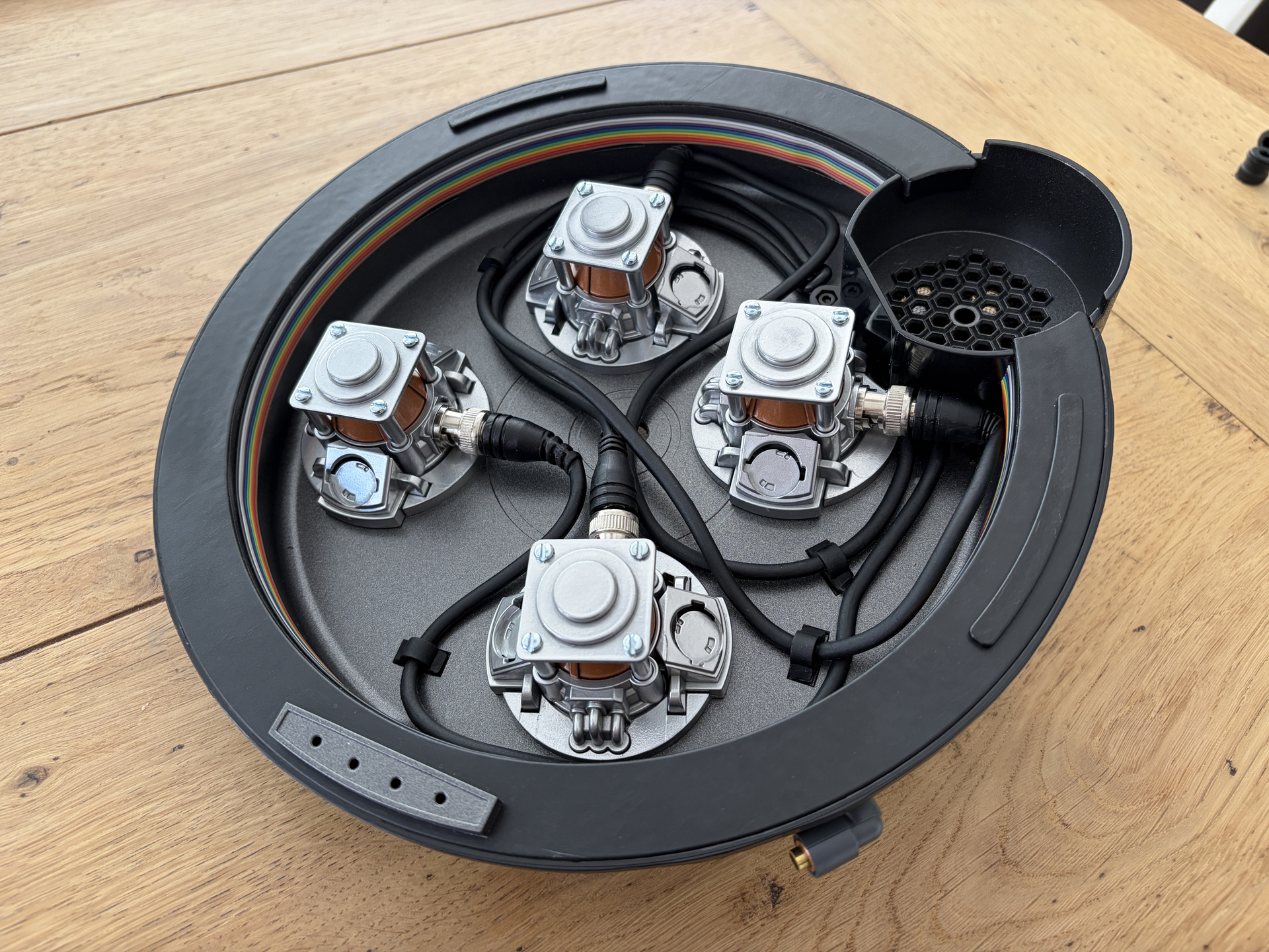
With that done, it was time to reassemble the cyclotron lid, and I’m so happy with how it turned out:

Good to finally start reassembling parts after all the painting, and good to get a piece complete… well, almost. I’m having an absolute nightmare with the CRT emitter tubes, but more on that shortly.

I also finished off the ion arm and put that back on the pack, just need to attach the hoses:

I used 3D printed replicas for the long resistors, and for the stubby PH-25 one, I just kept the one that came with the pack but sprayed it Tamiya semi-gloss back + gold. I’m in two minds over whether to buy actual Dale resistors. They look authentic, but they’re also quite expensive, plus most of the ones available are vintage so look old, which I can’t help thinking would look at odds with my fresh build aesthetic. I also installed a much better red power switch as well as a proper strain relief for the blue hose, and I also replaced the silver screws with black hex M3 bolts.

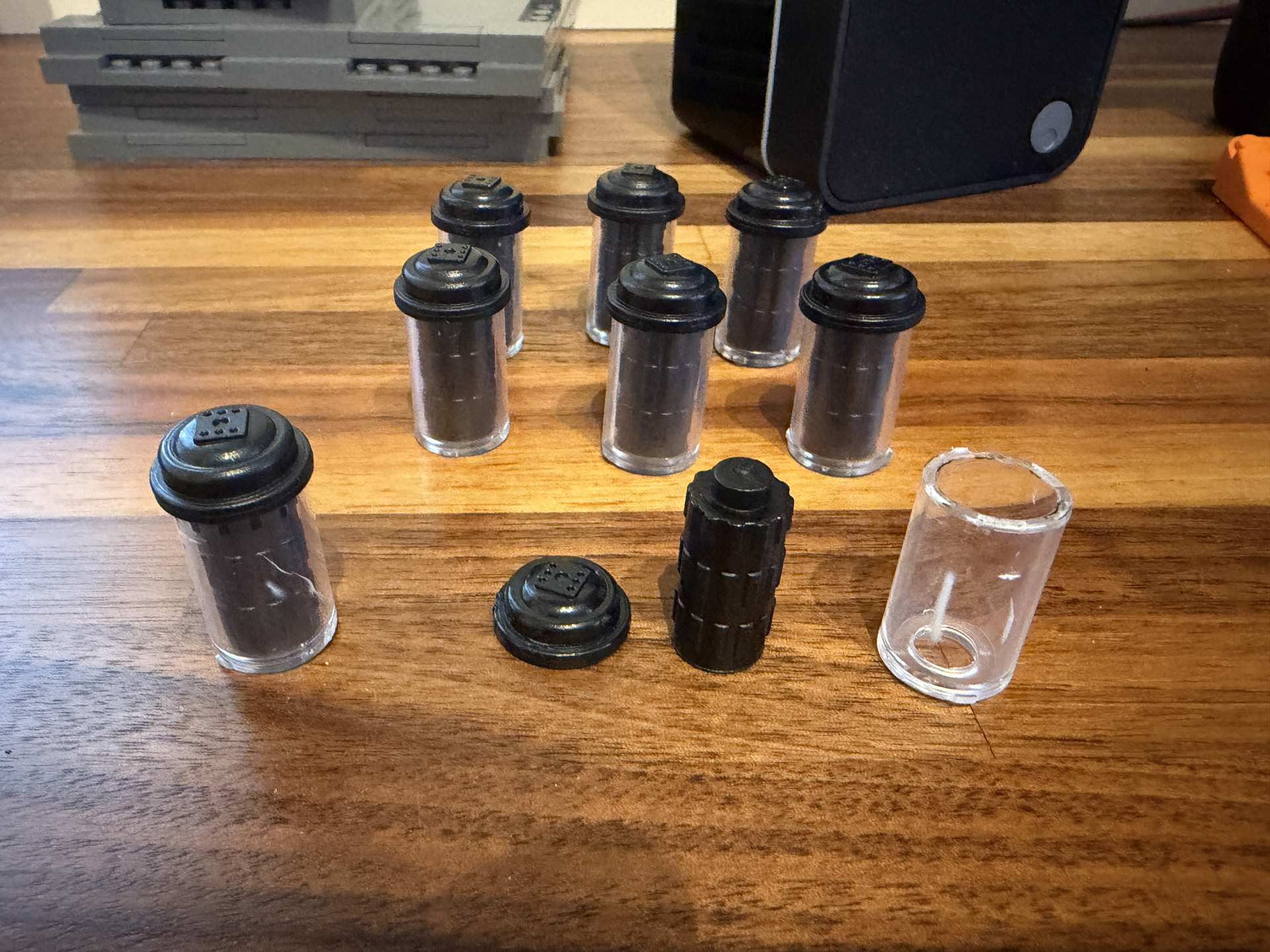
Back to those CRT emitter tubes, these are the clear tubes that have the black inserts and caps. I’m having a nightmare getting them open. I could just leave them and just paint the caps chrome silver, but I want to open them up and paint the inside copper to match the rest of the cyclotron lid. Hasbro definitely didn’t make them to come apart though! There’s a video where someone prizes them off with a bottle opener. I’ve tried this, managed to get one apart, but cracked the clear tubes on two in the process:

So I have a plan. I’ve ordered clear acrylic tube, 11mm ID / 15mm OD which is the same as these. So I’ll just crack the remaining ones open to get the lids and the inserts, sacrificing the original tubes, paint the black parts, then cut new tubes. They won’t have the twist/lock mechanism to attach them to their respective bases, but I’m not going to be taking them on and off so I’ll just find a way to fix them in place.

Anyway, that’s everything from the last couple of days, but plenty more to come! Next up will probably be detailing and reassembling the inner cyclotron.
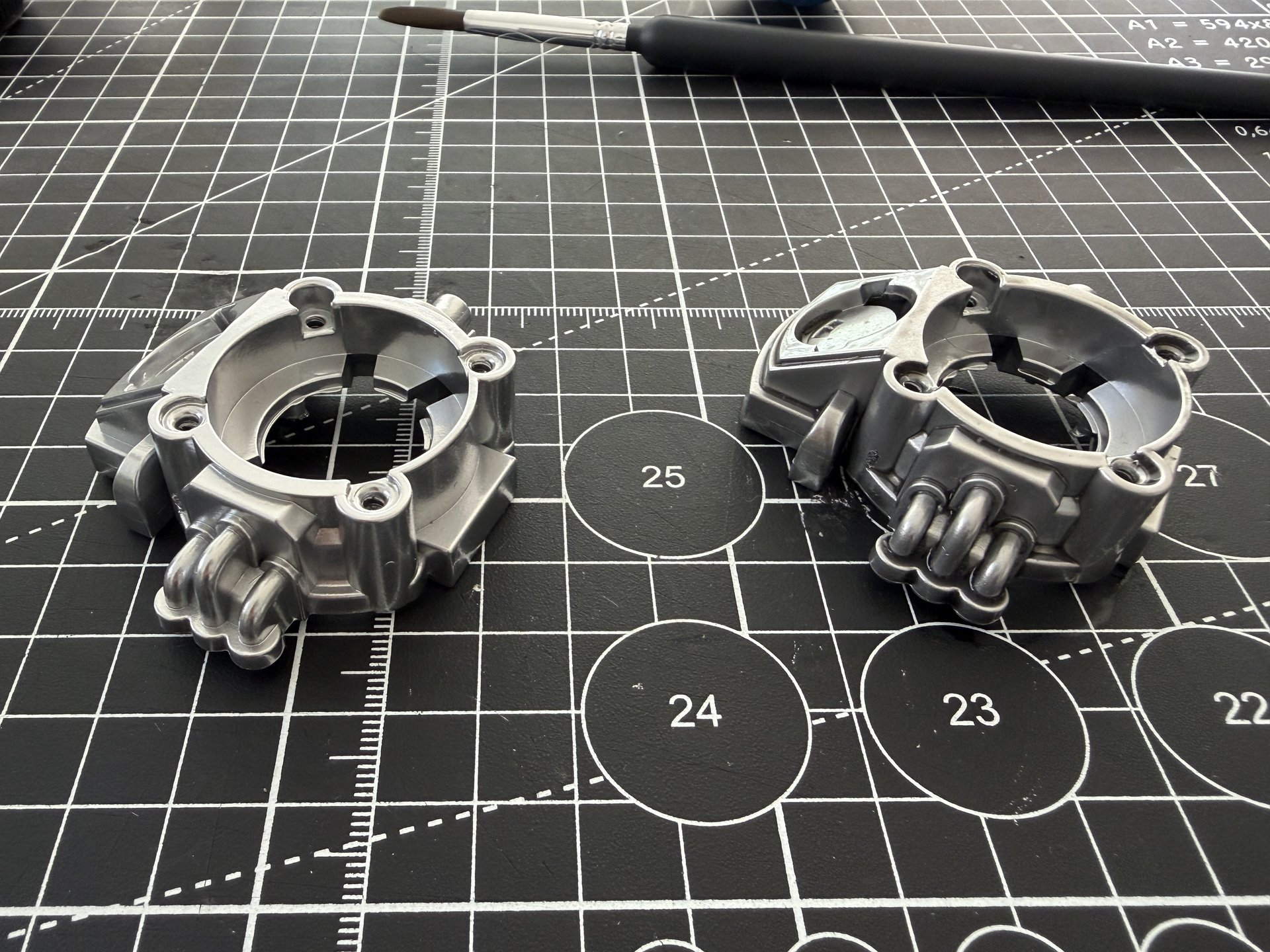
EDIT: Okay so the clear acrylic tube arrived today but it’s the wrong size. The 15mm OD is fine, but the 11mm ID is too small so the black inserts won’t fit in it. So I’ve ordered some 12mm ID / 15mm OD instead. Let’s see how that turns out!
1 Like

Perfect thank you so much!

Is there a trick to getting these off? love the way yours turned out. im waiting to install some parts from Charlesworth on my emitters. I might make the curved pipes brass/copper in color so they pop out more

Yeah I did think about doing the curved pipes copper too, trouble is I don’t have a copper pen or brush paint, and they were too fiddly to mask and use my copper spray, so I decided to leave them as they are, which I’m happy with.

Removing them is not hard at all, the trick is that there are a couple of steps you need to go through before. First, you need to prise the inside and outside of the cyclotron lid apart by breaking the six tabs inside, as per this video. It’s not as scary as it looks, you just need to be careful to not warp the plastic, so I used proper automotive panel removal tools, but anything wide and flat should work. I wouldn’t use a screwdriver as the force will be concentrated in too small an area and it will bend the plastic. You need to use something flat to spread the load as you lever them apart.

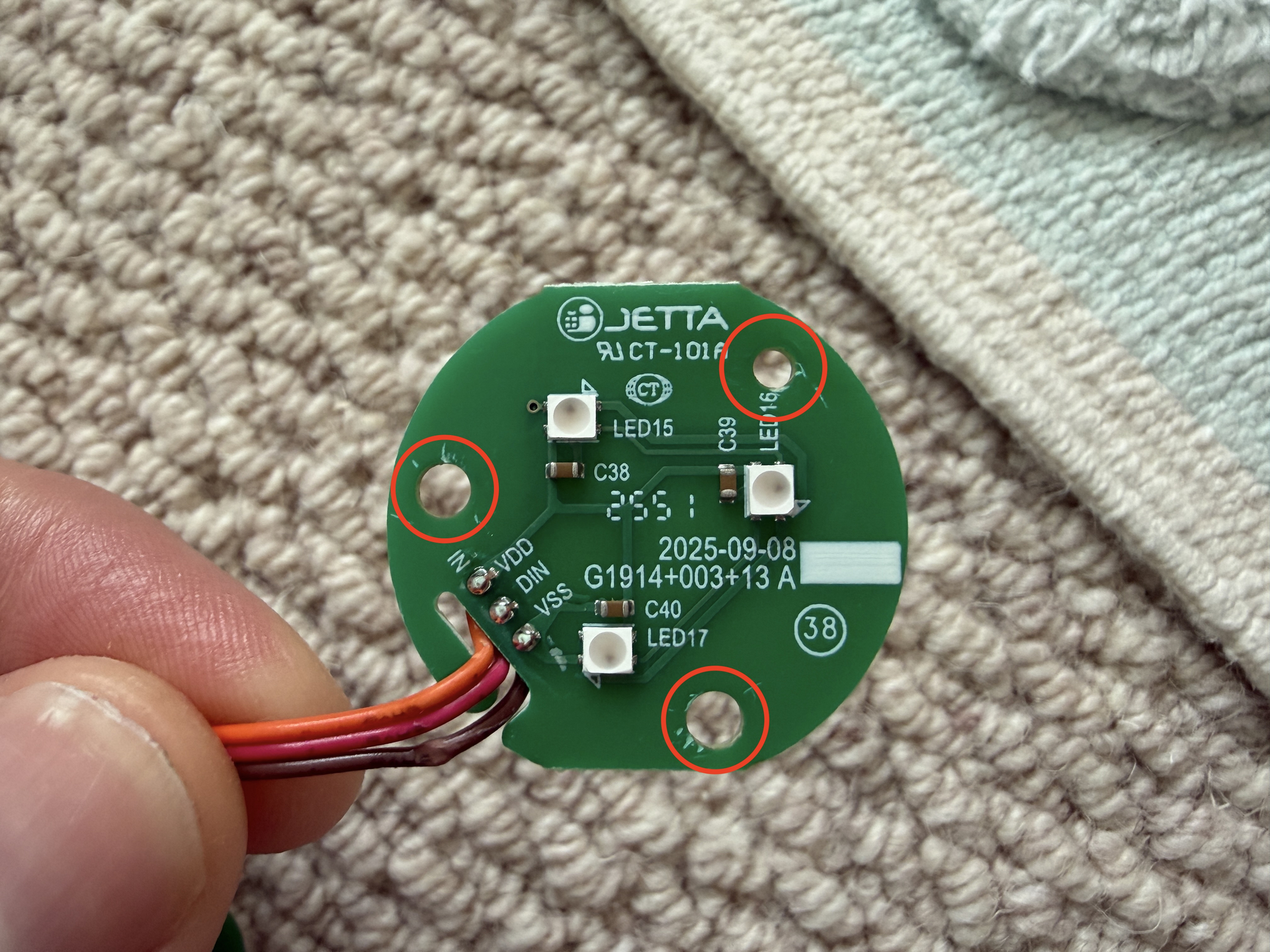
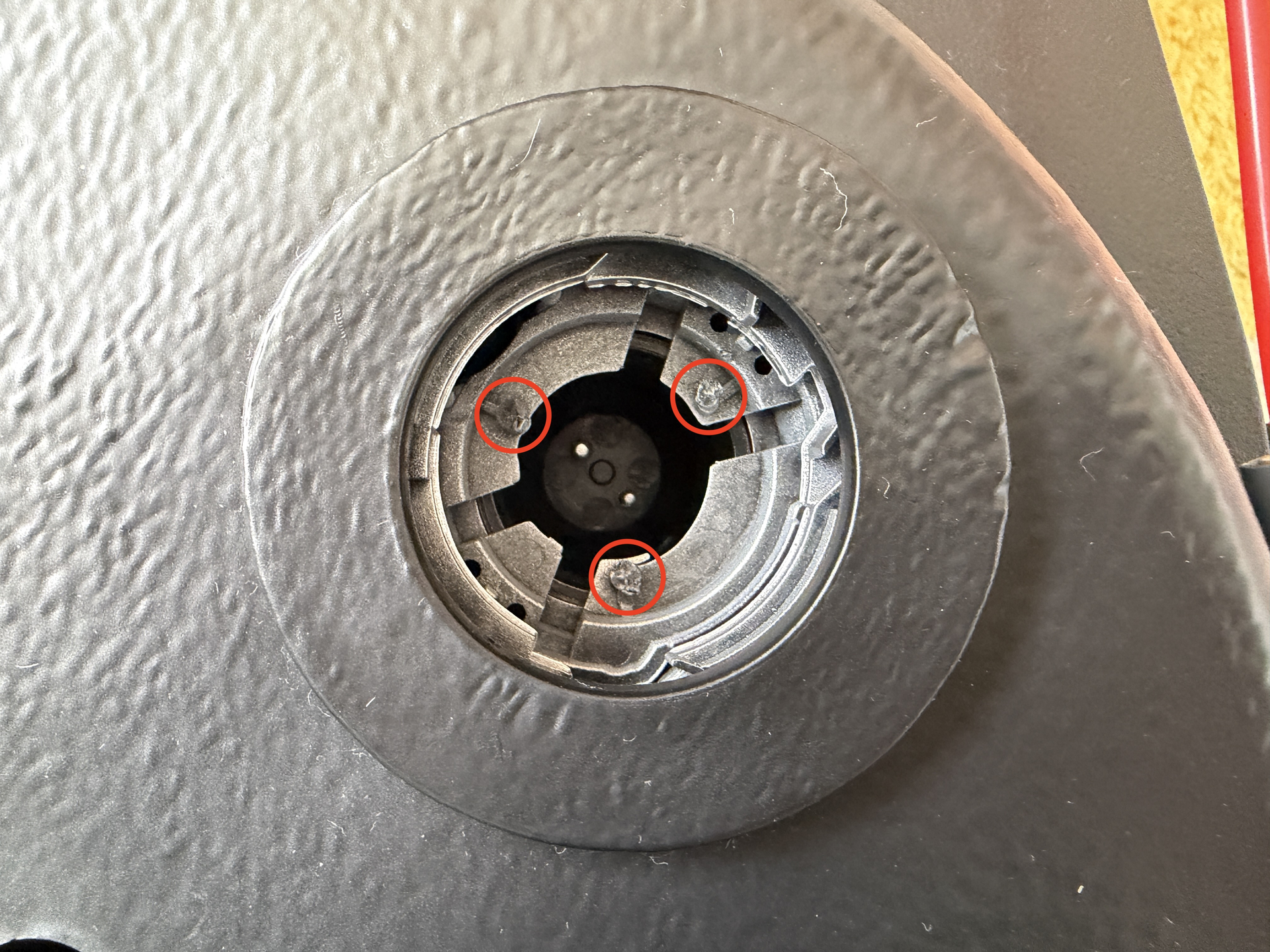
In fact, once you’ve got the lid separated, pretty much everything else is held in by screws, including these parts, so removing them is just a case of unscrewing them, apart from the second small complication which is that the round green LED PCBs are fixed to the underside. They’re fixed in by three black points which are almost like plastic rods poked through three holes that have almost been squished down to hold each LED PCB in place. It’ll make more sense once you see them, but I found the best way to get them out was to use side cutters to trim the tops of the three points off (on each LED PCB) which will weaken them, then push the LED PCBs through from the other side so they pop out.

Mine still work fine so I can put them back using glue if I wanted to, but I’ve actually ordered a GPStar kit so probably won’t be using them again.

Once you’ve done those two things - pried the lid apart and removed the LED PCBs - everything else is easy to remove just by unscrewing the screws.

Okay just to make that last point make sense a bit more, below is a photo of the underside of one of those pieces, after they were reinstalled on the inside of the cyclotron lid, but this photo was take from the outside of the lid. I haven’t got any LEDs or lenses in there at the moment, so you can see the three chewed up nubs that used to hold the stock LEDs in place:

You just need to find a way to chew the ends off, then the LEDs will pop out. I used side cutters, but you could use a Stanley knife or scalpel blade. Below is one of the removed LEDs, with the three corresponding holes that these nubs used to slot into:

1 Like

This is great stuff. I’m doing something similar with mine. Looking forward to more updates, and thanks for sharing your progress!

Not a problem at all! I’m enjoying the process, and more to come. This week I’ve been detailing the back panel of the inner cyclotron as well as dealing with those CRT emitter tubes, so more updates to follow shortly.