Hasbro 1984 Proton Pack BIG Overhaul and Customisation

How did you cut off the fake bolts? I’ve been thinking of doing that.

Also from what I’ve seen, to remove the HGA once you unscrew everything you have to get a wedge in there (screw driver or a plastic pry tool) and pop the glue off the band that wraps it.

Hey @spooky ahh that would make sense, seems Hasbro used screws and glue quite a bit, as with the n-filter cap, but it makes it hard to know how to disassemble certain parts.

To remove the fake bolts, I used side cutters to cut most of them off, then to get the cut as flush as possible, I finished it off with a Stanley/scalpel blade. You have to be really careful not to slip otherwise you could scratch or gouge the surrounding plastic, hence it would have been a lot easier with the HGA removed as some of the angles were quite tight, but if you take your time you’ll be fine. I watched this video before, he’s done quite a few useful videos on the pack now:

Also quick correction, the bolts I used were M6, not M5.

Once the fake bolts were cut away, I then just used a drill to drill holes for the new bolts. I forget which size bit I used, but if you just make sure to go slightly smaller than your bolt shaft, the bolts will then have something to bite into.

The only thing with fitting these bolts though was that even though the M6 bolts themselves were pretty much screen accurate, the cut away fake bolts still left a slightly ragged circular shape which was very slightly wider and therefore visible even with the new bolts fitted, so I added some black M6 washers that I had, which covered up and also flattened those remaining ridges. Not 100% screen accurate, but looks absolutely fine to me.

3 Likes

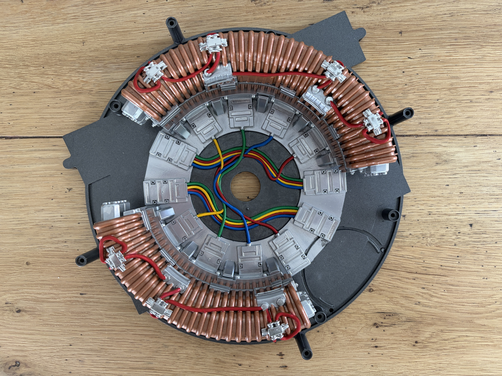
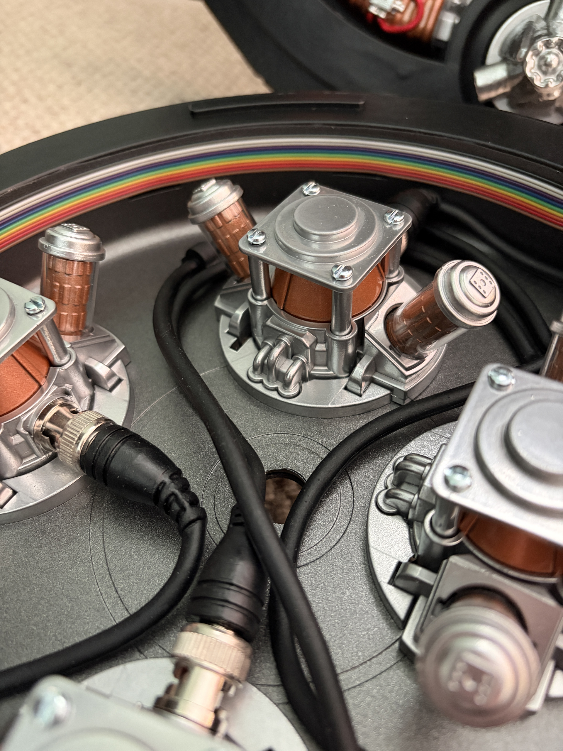
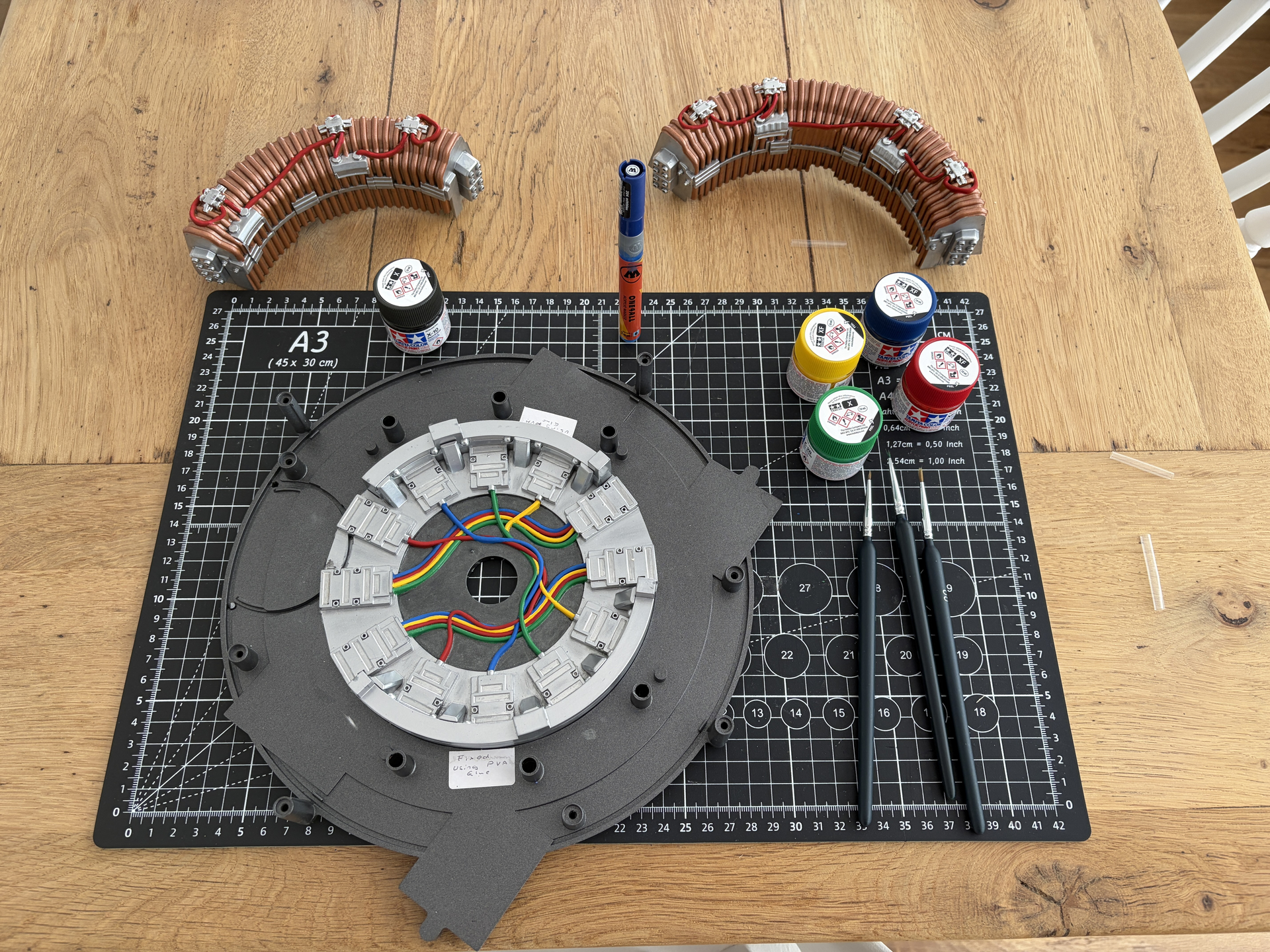
Okay so time for another update. Over the last week I’ve been mainly focusing on detailing the rear panel of the inner cyclotron section, which ended up being a lot more fiddly than I thought it would!

Long story short, I think the mistake I made, and something I would do differently if I was doing it again, was that I purchased a pack of Molotow One4All paint pens, which came in yellow, green, blue, red, white and black, i.e., the exactly colours I needed to do the fake wires. I’ve used Molotow pump paint pens in the past and they’re usually excellent, especially their liquid chrome which is amazing and probably the only chrome paint I’ve ever come across that gives an actual mirror chrome finish.

My thinking was that I would just ‘draw’ paint the wires, but this ended up not working out so well for three reasons:

  1. The pens only came with 2mm nibs, but this was way too wide for the level of detail required. Fortunately, I had a fine detail brush and I was able to open the pens up and directly paint the wires instead.
  2. The coverage wasn’t as good as I’d hoped. Normally Molotow pens give excellent ‘one coat’ coverage, but with these, I needed to do multiple passes, but even then, some parts still looked a bit patchy.
  3. The colours just weren’t right. The yellow looked a bit insipid, the green was too dark, the red looked faded. The only one I liked was the blue, but overall they just didn’t give a realistic ‘feel’ of being real wires.

So after I spent a load of time on it, I decided to switch tack and ordered some Tamiya Mini X- paint pots. These were much better, and I’d use these from the start if I were doing it again, apart from the Molotow blue which was actually okay. By a happy coincidence, I also happened to have a pot of Tamiya X-10 Gun Metal Grey, which was almost identical to the Jenolite Gun Metal Grey I used for the base originally, so I was able to brush paint back the dark grey centre circle. From a distance, you can hardly tell its a different paint.

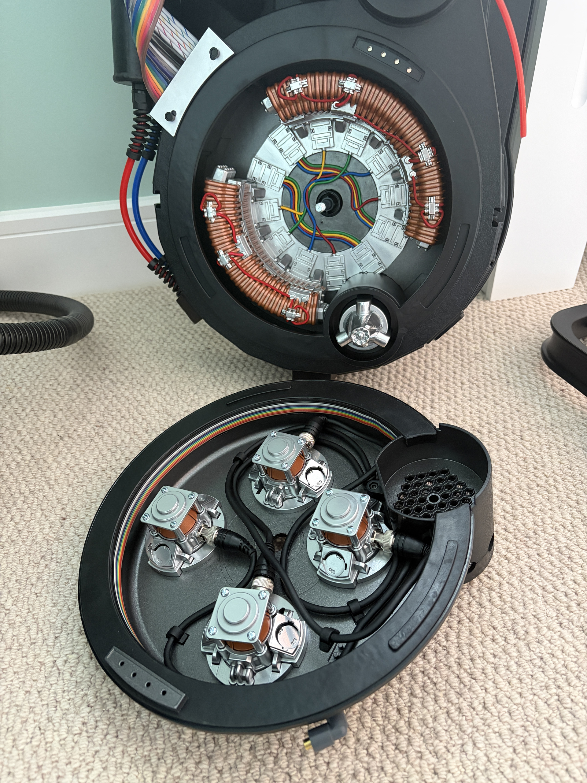
Here are some photos of the finished results:

With the copper ‘kidney’ pieces reinstalled:

Back in the pack, and next to the cyclotron lid:

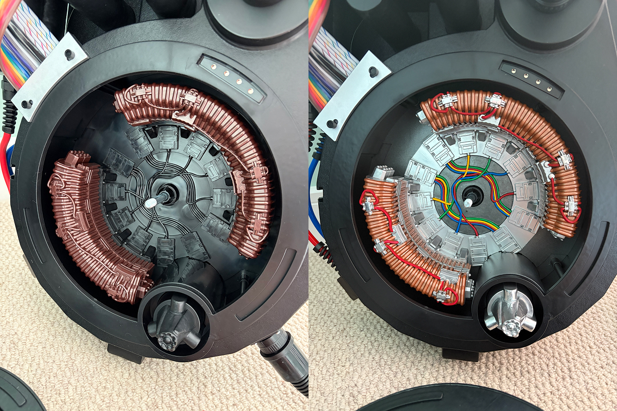
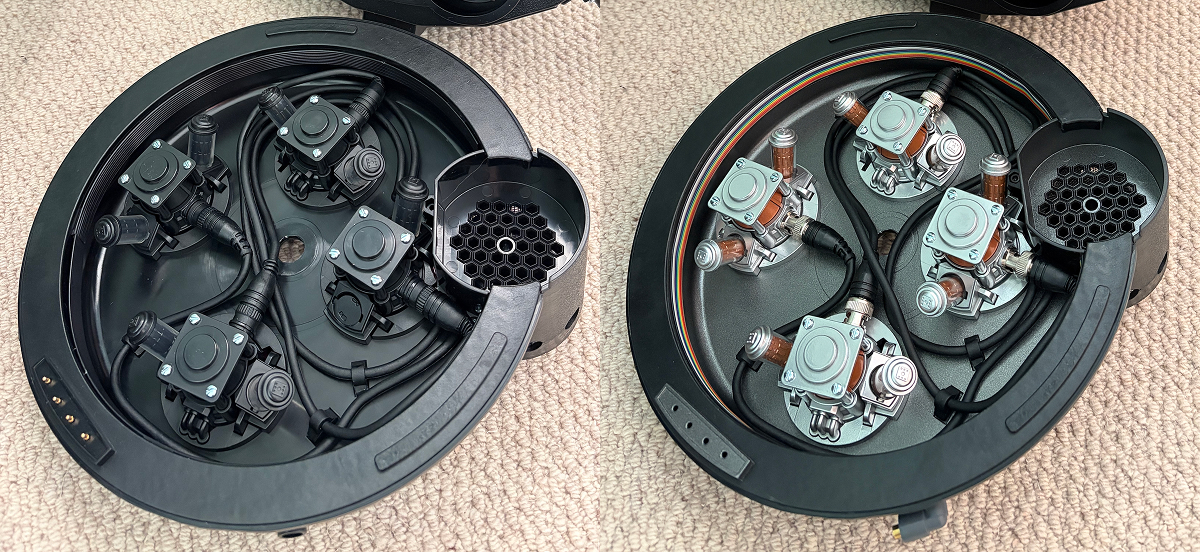
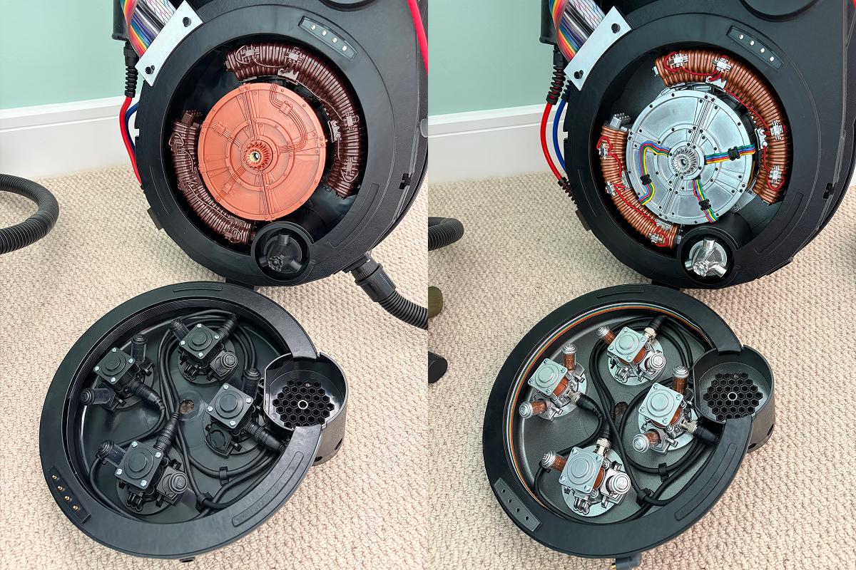
A quick ‘before and after’ looking back to how it was originally versus now:

It’s definitely all starting to come together! I might actually purchase some real coloured wires to create a fake loom to go into the cake, to make it look like it’s actually connected to the pack.

Now back to those CRT emitter tubes. So I’ve made progress on these. I managed to source a better size clear acrylic tube, which is 14mm OD x 12mm ID x 305mm L.

I tried some other sized tubes, but they were the wrong size. 11mm ID is too small for the inserts, and 15mm OD is too big to fit back into their corresponding circular housing in the cyclotron lid, perhaps not if they hadn’t been painted, but when I test-fitted a 15mm OD option, it didn’t fit. So 14mm OD x 12mm ID is the correct size. I’ve measured the inserts and I think 22mm will be the correct length to cut each new tube, but I haven’t tested this so don’t take that as 100% accurate just yet. But 305mm length should be enough to cut another eight with some left over.

I also found a way to easily remove the black caps and inserts from the original clear tubes, but for the sake of full disclosure, it’s completely destructive to the original clear tubes, so only do this if, like me, you’re planning to replace those clear tubes with your own versions (or you’ve found someone who sells replacements).

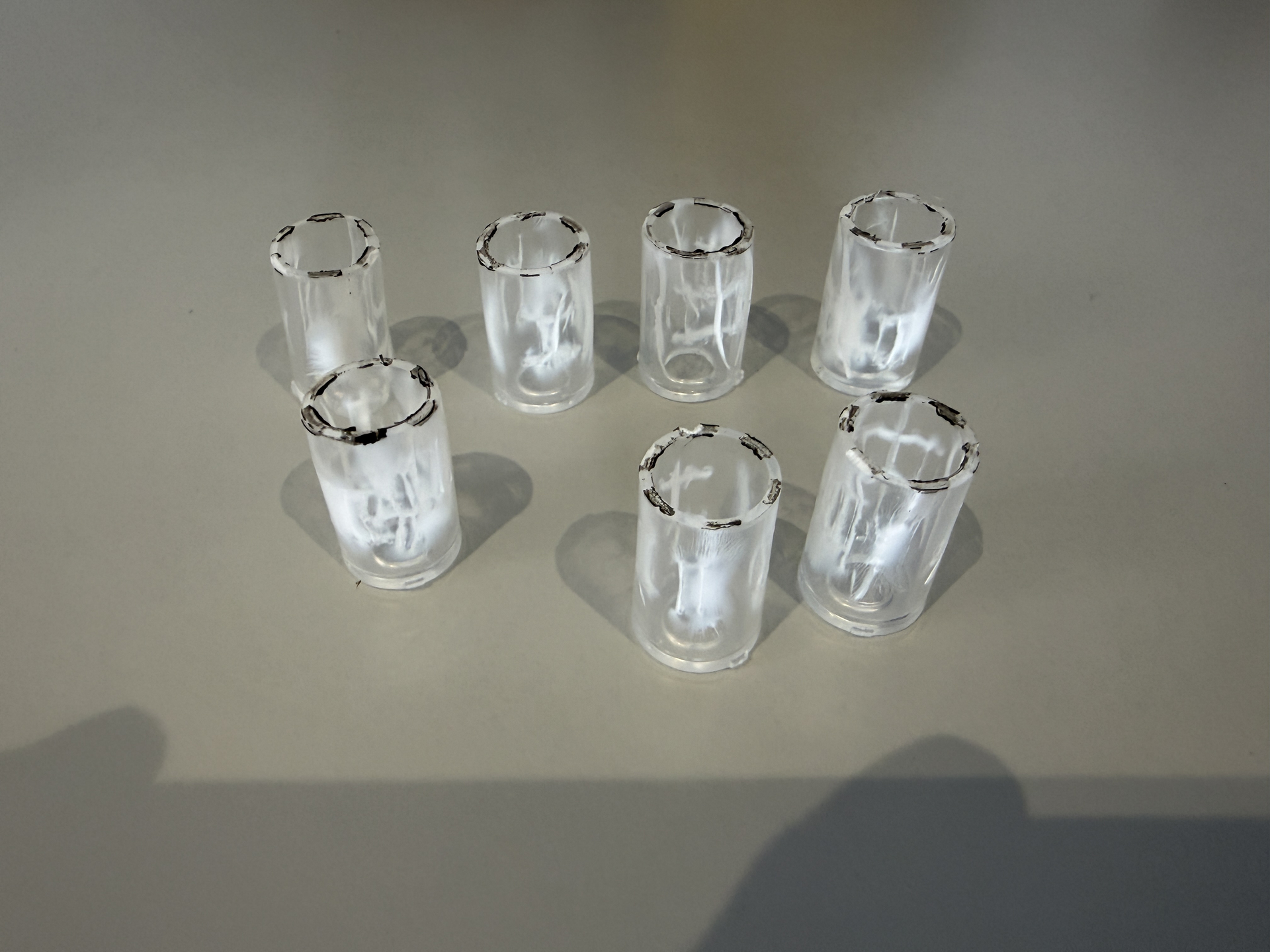
The way I did this was to just use my vice grips to clamp down and squeeze the middle of the tubes. You could use pliers, but I found vice grips work best. The tubes don’t shatter like I thought they would; instead they just squish and flex from a circle to an oval, but it’s this change of shape, going from a circle to an oval, that breaks the glue seal with the plastic caps and allows them to just pop off.

The caps were completely fine, and the good news is that the black inserts aren’t actually hard plastic either. They’re more like rubber, but not rubber, perhaps something like polyurethane, so squishing the original clear tubes doesn’t damage them at all.

Here are the original tubes after being removed. As you can see, completely unusable now:

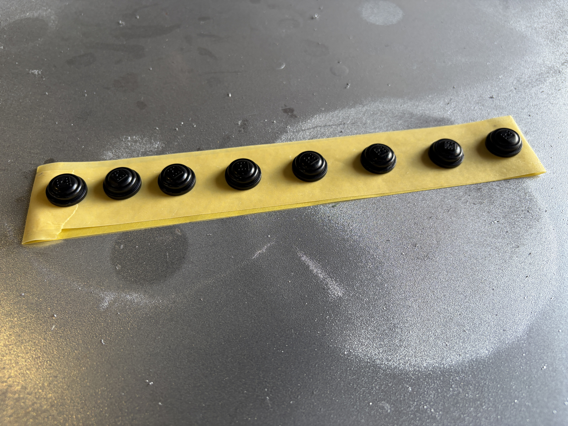
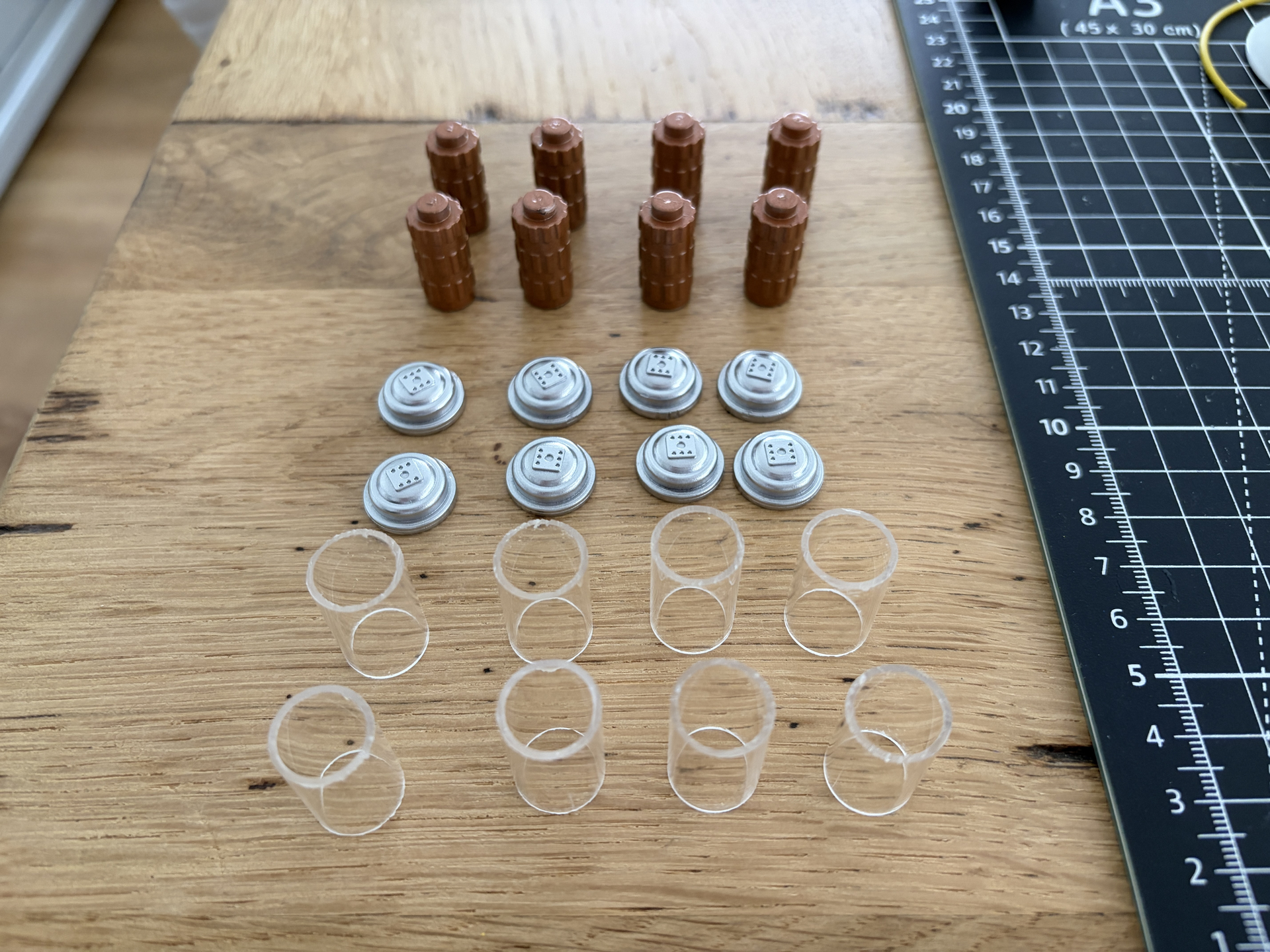
The black end caps and inserts ready for paint (using doubled over masking tape so the spray paint doesn’t blow them away):

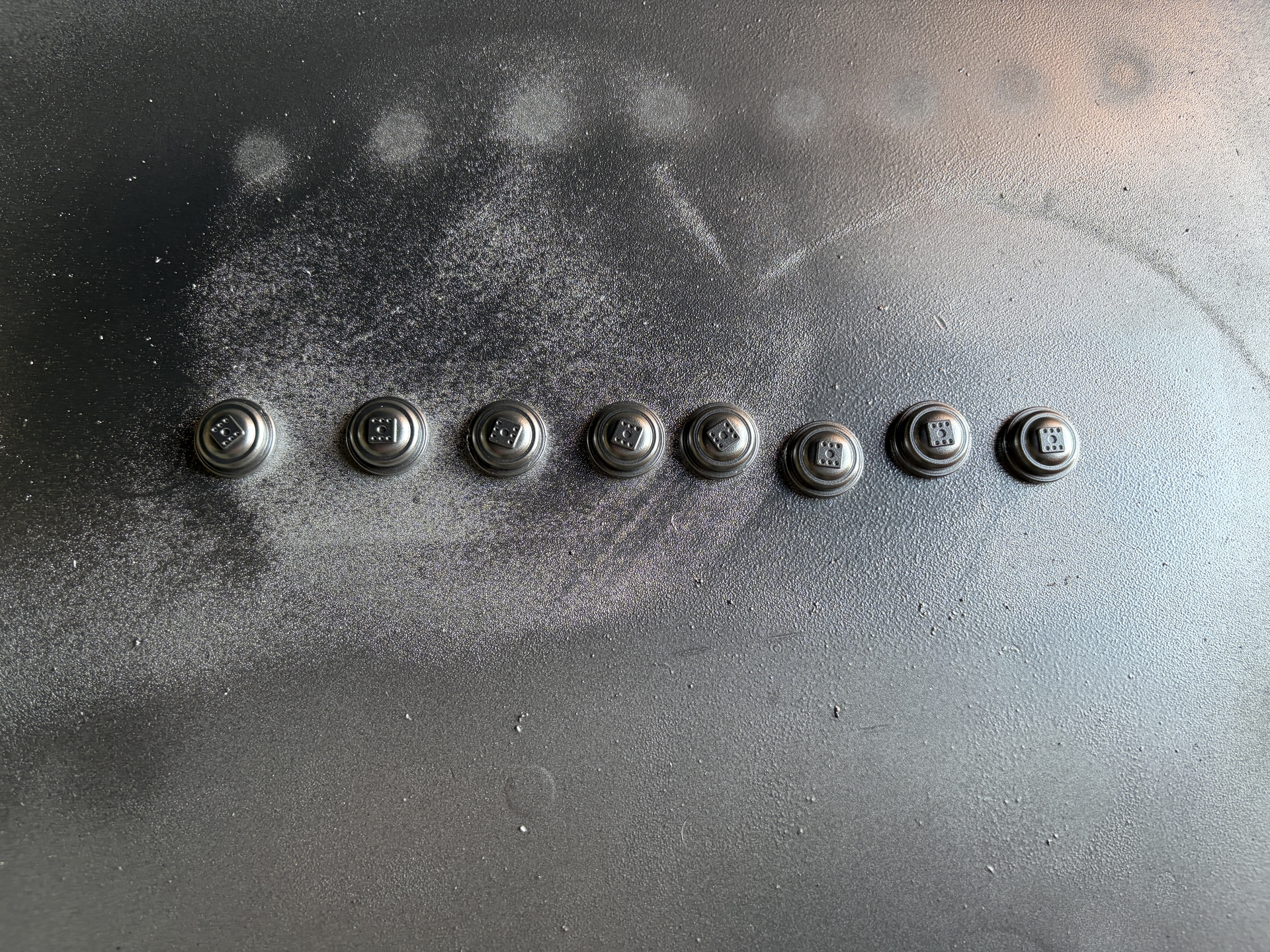
And then after being sprayed (I actually did both sides of the caps, just haven’t shown it here):

I’m going to leave them to dry a few days before I start cutting the new clear tubes and reassembling them, so I’ll share a further update once they’re all done.

Then just to finish up, I’ve started detailing the cake, getting that ready to go back into the pack:

By a happy accident, I found a way to slightly distress the open sections between the frame, which gives it a slightly more screen accurate look, and I used Tamiya X-18 semi-gloss black paint for the small bolts and wire holders.

I want to do a decent job with this, but longer term I want to get the GPStar inner cyclotron light kit and aluminium/PLA cake to add to the base kit I’ve ordered, so this one probably won’t be in there forever.

The wires are also a lot smaller than on the rear panel I showed earlier, so I think it would be really hard to detail paint them and still get a neat job, so I’m actually going to try adding real wires over the top. It will either look really good or an absolute disaster, so I’ll share another update once that’s done!
2 Likes

Wow! A little bit of paint goes a long way!

1 Like

Thank you! Yeah I definitely think the inner cyclotron is the weakest area on the 1984 pack, just in terms of looking cheap and plasticky, but Hasbro have given us a good base to work with, and I’m really pleased with how it’s turning out!

2 Likes

Hi there! Apologies for not seeing this post earlier; I rarely log into GBFans nowadays since the site runs like dogwater on my PC. I’ve done two HGAs (one on the HasLab, one on the 84) and have removed it without damage to either the HGA or its bracket. No dremel, no cutting, nothing. There is absolutely a correct way to remove it, and sadly most people seem unaware.

First, obviously, remove the two screws holding in the bracket. Then, my method is to use a thin blade (I used the safety blade from the Tamiya Basic Tool Set since I had it laying around), inserted in between the surface of the HGA and the underside of the bracket at the point indicated by the arrow in the photo below, with the sharp side of the blade facing upwards:

Push the blade in all the way until you feel it bottom out. Once it has bottomed out, slowly and carefully pull the blade upwards along the curve of the bracket. What this does is cuts through the superglue that is securing the bracket to the HGA. At certain points you’ll hear and feel pops that will make it seem like you broke the knife off inside, but you didn’t, it’s just the glue coming loose. Once you have slid the knife all the way to the opposite end of the bracket, remove the knife entirely then grab the bracket and yank straight upwards. The last tiny bit of glue will give way, and off comes the bracket.

With the bracket removed, the HGA turns about 30 degrees to line up the tabs in the HGA with the holes in the crank gen wall, and slides right out. Easy peasy.

4 Likes

Thank you so much for sharing! I’m going to try this out, it’s been the one part of the pack I’ve really struggled with removing.

1 Like

Thanks @nomake-wan that’s super helpful! Too late for me unfortunately but I wish I’d known this when I was removing the fake bolts as it would have made the job a lot easier. Having the HGA removed means you can get a nice clean chop cut to slice them off, so helpful for anyone still looking to do this.

1 Like

Yeah, again, I’m sorry I didn’t see this topic sooner. I mostly hang out on Discord and in some of the Hasbro modding groups on Facebook instead.

As for the bolts, M6 does work just fine (and were probably exactly what got used on Frozen Empire considering all the UK prop production), but the originals were 1/4-20. Just as a reference.

That makes sense. I believe the aluminium motherboard I’ve ordered from Redman comes with 1/4-20 fixings too.

Okay some more progress to share. Not too much this week as I’ve been away, but first up, I managed to complete the CRT emitter tubes. I ended up going with 23mm for the length. The inserts are 22mm, not including the nub at the top that fits into the caps, so 23mm gave me 1mm of play, which worked out fine:

The tricky bit was finding a way to cut them and also get a good 90 degree cut. First, I tried a junior hacksaw with a fine cut blade, which cut the acrylic fine but made it hard to get the 90 degree cut, so then I tried my DeWalt electric mitre saw, which felt like using a hammer to crack a nut, and I was worried it might shred the acrylic, but it actually worked fine. I already had a 60T fine cut blade which probably helped. The cuts aren’t 100% perfect, but they won’t be visible so it doesn’t matter too much.

I then used super glue to fix them in place. I didn’t want to get glue on the inserts, so I carefully applied a tiny bead around the lip of one end of each tube to attach the lids, then inserted the inserts from the other end, then applied another bead of glue to the other end of the tubes to fix them to their respective places in the lid:

It’s a bit more permanent than I would have liked; I would have preferred to retain the twist-lock mechanism of the original tubes, but realistically, I’ll never want to remove them. The whole pack will spend most of it’s time as a display piece, occasionally being worn to a Comic Con, but they’re held in place pretty solidly now so they should be fine. I know ‘screen accurate’ would have been to make the inserts goldish-silver, like they are in Afterlife, but I really like the copper as it matches what I’ve used elsewhere.

Here’s a before/after compared to how it was originally:

I’m really happy with how it turned out, and it’s good that it’s another key piece finished!

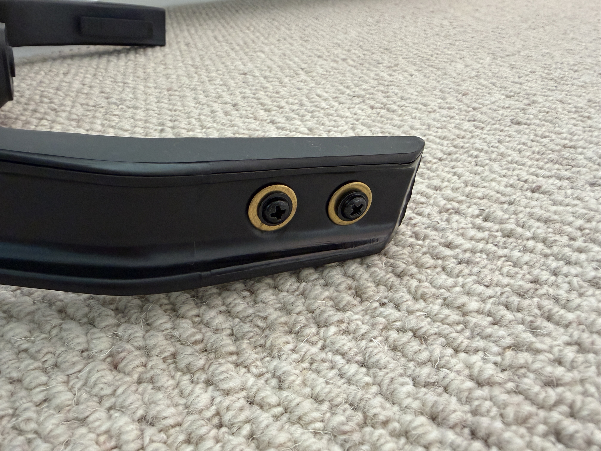
Another small detail is that I switched the silver screws that came on the bumper to slightly more accurate brass washers and black screws. The washers might actually be copper, I’m not sure, but they look much:

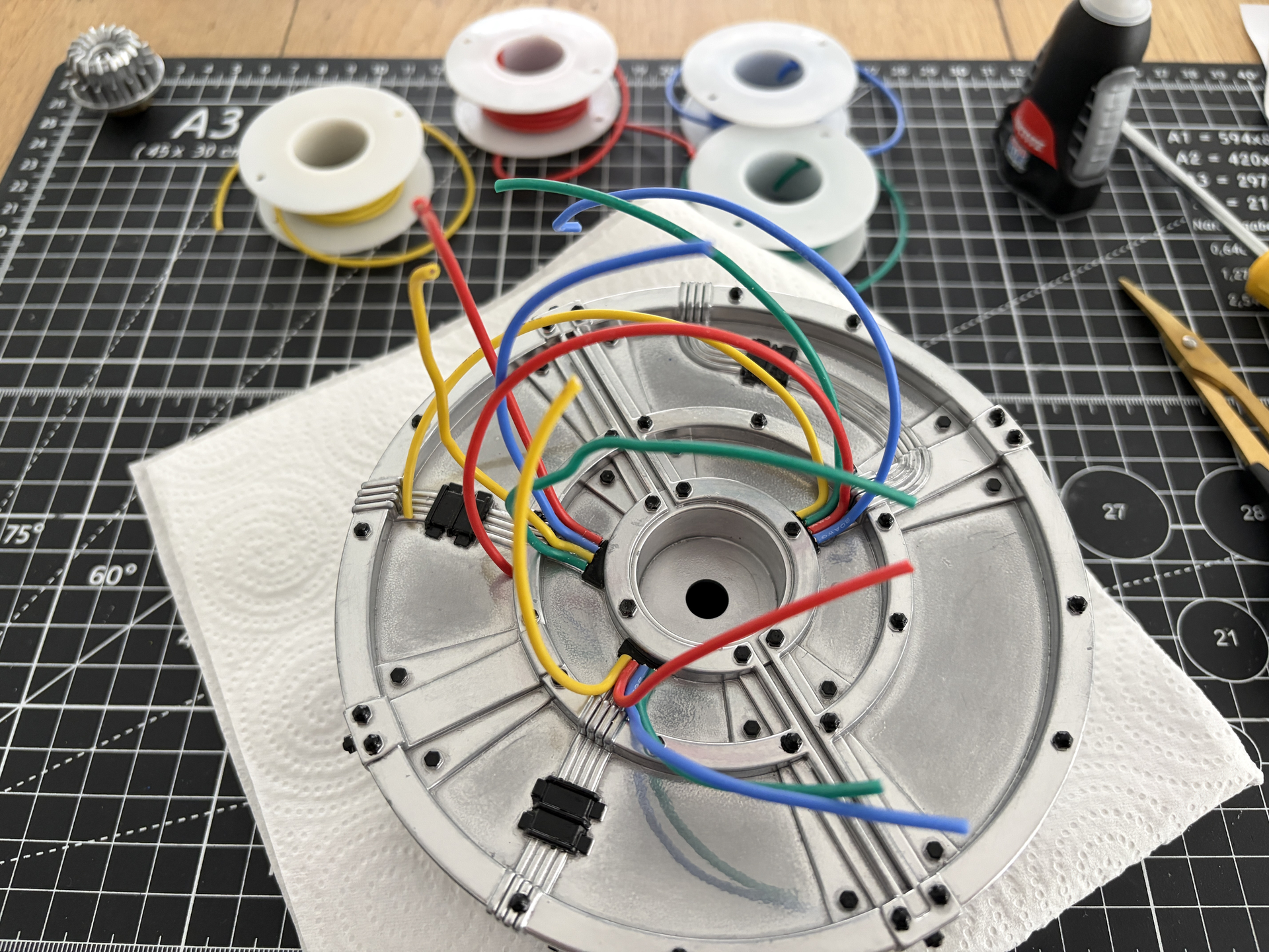
I also made a start on glueing the real wires to the cyclotron cake. I bought this pack of real 1.8mm silicone 20 AWG electrical hook up wire from Amazon for around £10, which came with all the right colours: yellow, red, blue, green, and also black and white but I probably won’t need those.

Then, as I already had the super glue out, I start glueing the wires over the the moulded versions on the cake:

It looks a lot better in real life than this photo, it actually looks really good and much more realistic, but it’s quite time consuming as you have to glue each wire, then hold it in place for around a minute until it sets, then do the next wire. I only spent around an hour on it, hence it’s not finished, but next I’ll need to continue gluing the wires in staggered intervals so I can mould them along the route of the original moulded versions, but when it’s all done, the real wires should cover the original moulded versions and it should look really good.

That’s it for this week, but some more good news - the GPStar kit has been dispatched, so I’m looking forward to hopefully getting that in the next few days.

2 Likes

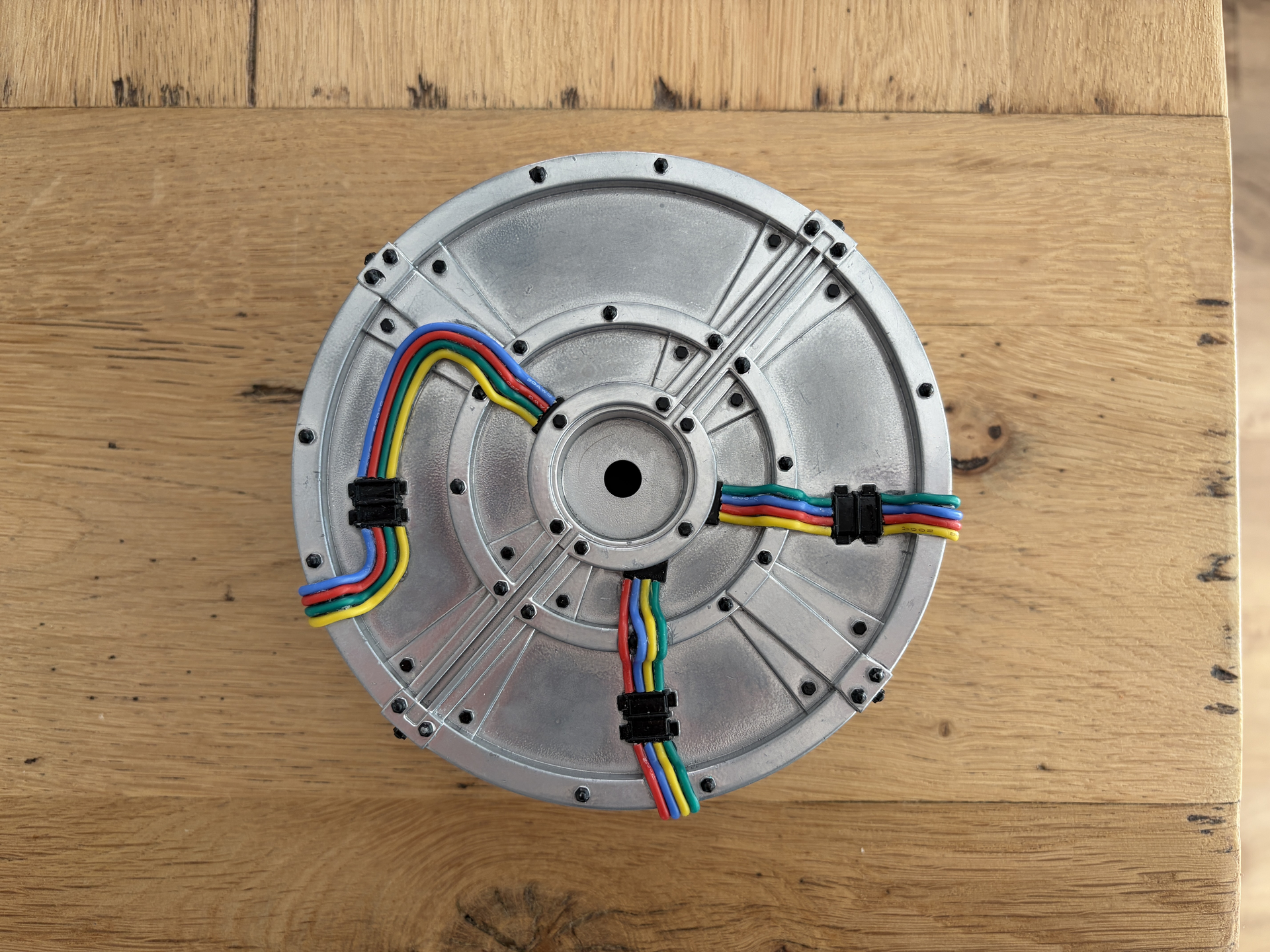
Okay so I finally managed to get all the real wires glued down onto the cake. Took the best part of a week, not because it was particularly time-consuming, it’s just that you have to glue one part of a wire or wires and then wait for it/them to dry properly for at least a few hours until it’s strong enough to manipulate the wires into the next position.

It was fiddly work, but I think it looks really good and I’m really happy with it. It’s one of those jobs where, if you look really close, like just in front of your face, you can still see some of the imperfections where either the glue has seeped out slightly (virtually impossible to avoid), or you can just about still see the original moulded wires, but if you look at it from more than around two feet away, it looks really good. I think for what this is, it’s a great improvement and way better than if I had tried to paint those moulded wires.

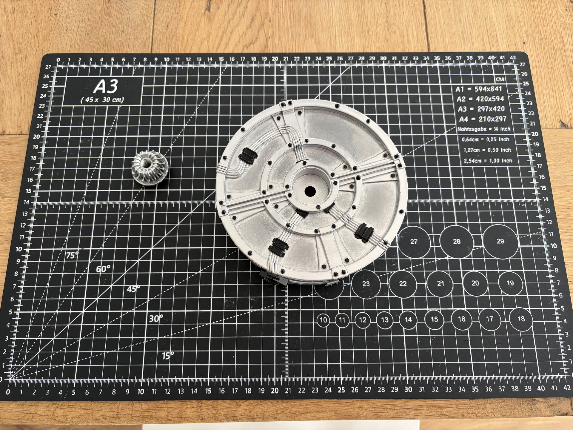
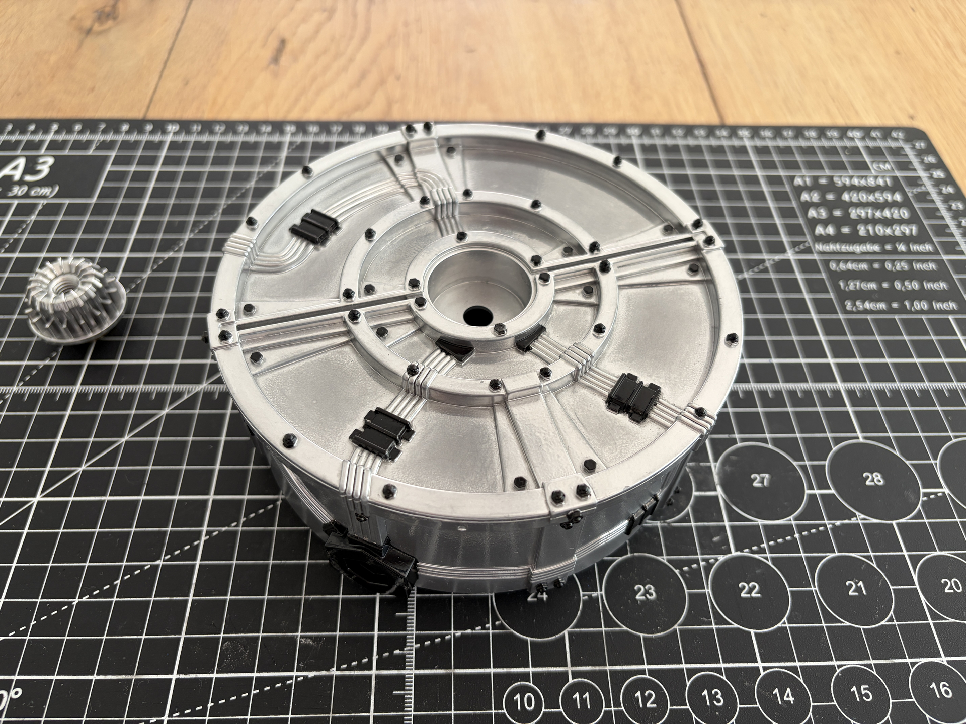
So I can finally share a proper ‘before and after’ with everything in the cyclotron section ‘done’, for now at least:

So I think I’ve taken this cake as far as I can and I’m really happy with it, but as I mentioned before, I’m actually planning to upgrade and get the GPStart inner cyclotron light kit to add the to base kit that I’ve just bought.

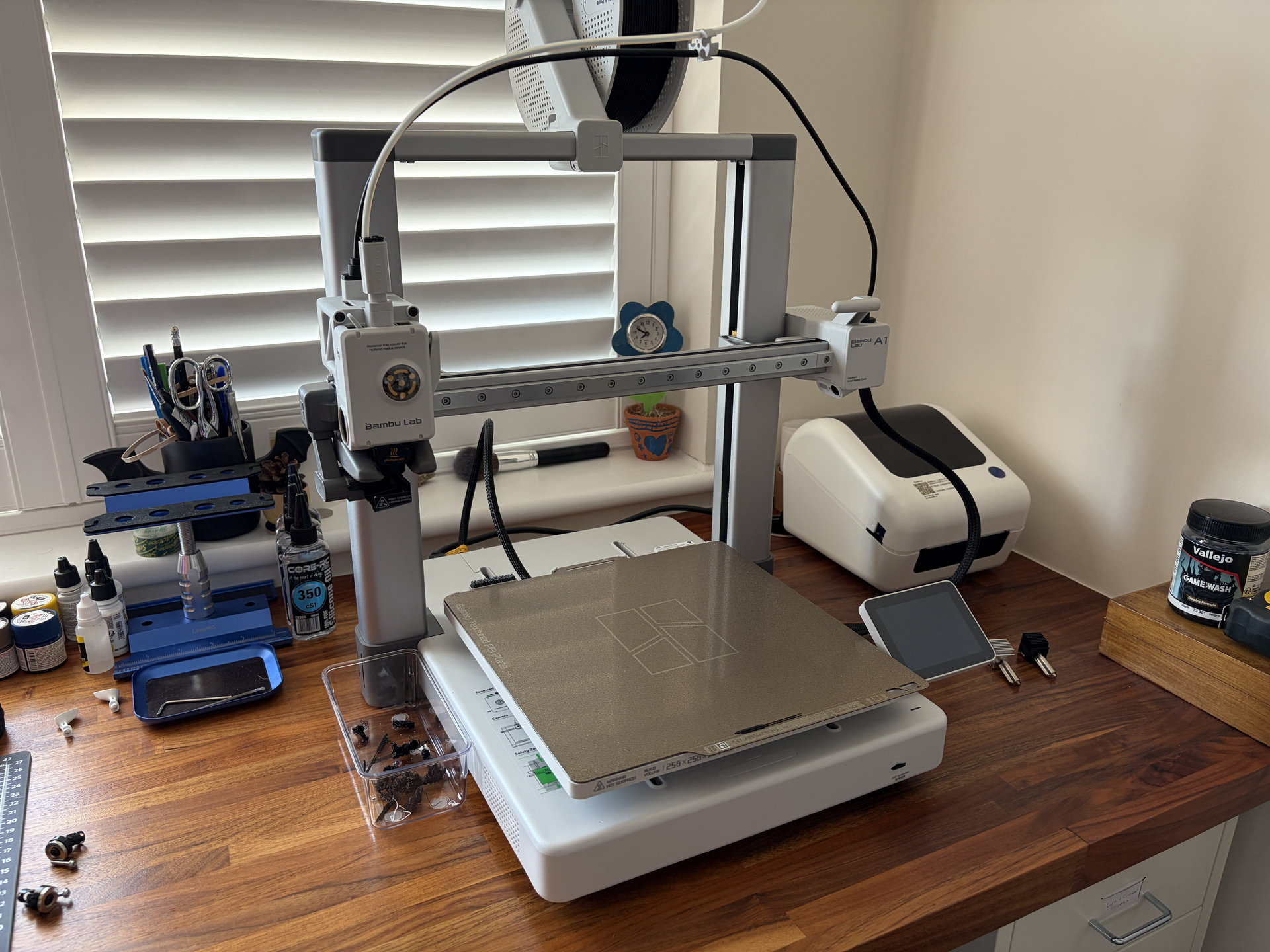
But I’ve changed my plans on that slightly. I was going to buy GPStar’s aluminium/PLA cake, which looks amazing, but instead I’ve bought… a 3D printer!!

Nothing groundbreaking there I know, but I’ve never owned a 3D printer before, and to be honest, I’ve been put off using 3D printed parts on this project, mainly because when I did my Spirit pack two years ago, I needed to order parts from a local 3D printer but they were quite textured and so I had to do loads of sanding/filling/sanding/filling etc, which I hated.

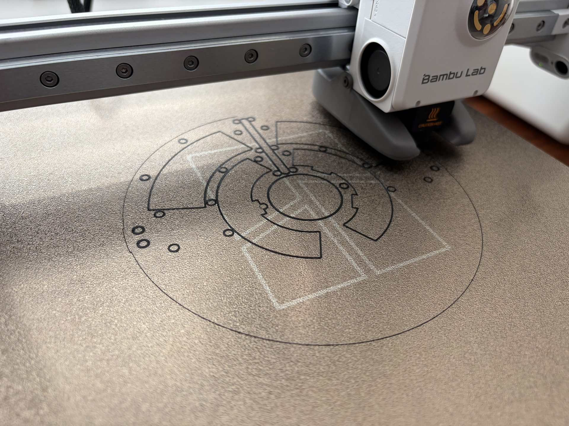
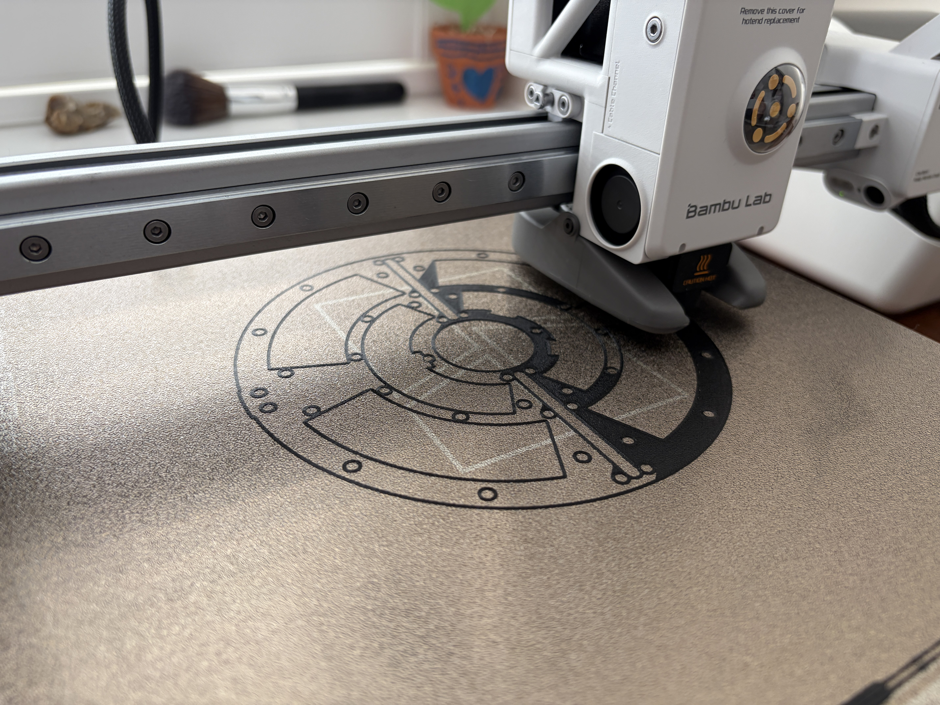
But I’ve seen good things about the Bambu Lab A1. It can handle really tight layer lines and I’ve also upgraded to the 0.2mm nozzle, so I think I’ll be able to produce detailed enough prints that I can then just use filler primer and paint without sanding and filling.

So I’ve purchased the TacoBelli inner cyclotron switch panel and cake, and I’m planning to print those myself, then just by the lighting kit on it’s own from Frutto Technology, who are also here in the UK where I am.

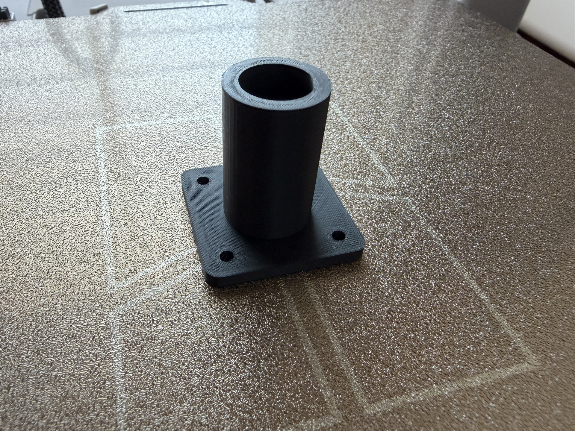
I already designed this little loom connector using Tinkercad, which will be to attach the new loom to the pack:

Because I bought the GPStar base kit, it only comes with JST wires to connect the pack to the wand. It doesn’t come with any kind of loom or quick release connector, which I’m fine with as I want a fixed loom and I already have some 20mm ID loom left over from the Spirit pack (which is the right size to fit on the wand end connectors) so I just needed to make this connector to replace the one with the screw fix that comes with the Hasbro 84’ pack. It’s actually a lot smoother than it looks in that photo, just need to blast it with some primer and paint.

So more updates will be coming shortly with all the new 3D printed parts, once they’re done.

4 Likes

Looking great so far!

Thanks!

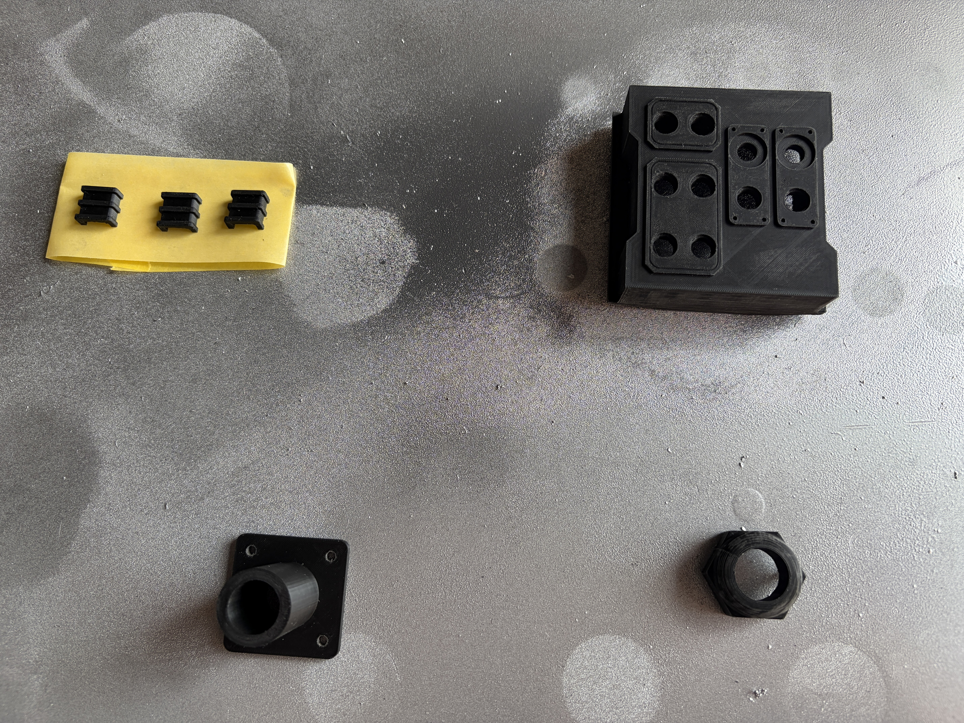
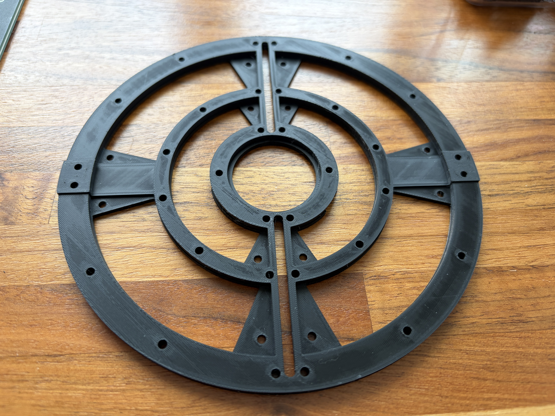
Over the last few days I’ve been 3D printing a few more of the parts. Here’s the inner cyclotron switchplate, cable guides, cable nut and my custom loom connector. Again, the photos make the layer lines look much worse than they actually are. The parts actually all feel really smooth, and the detail is really intricate:

The start of the cyclotron ‘cake’ top being printed:

And then the finished print, again super smooth and detailed in real life:

I’m actually blown away by just how good the Bambu Lab A1 is, especially given that it only costs a little over £200. Everything here has been printed with the optional 0.2mm nozzle and 0.06mm layer height, using their black PLA Pure.

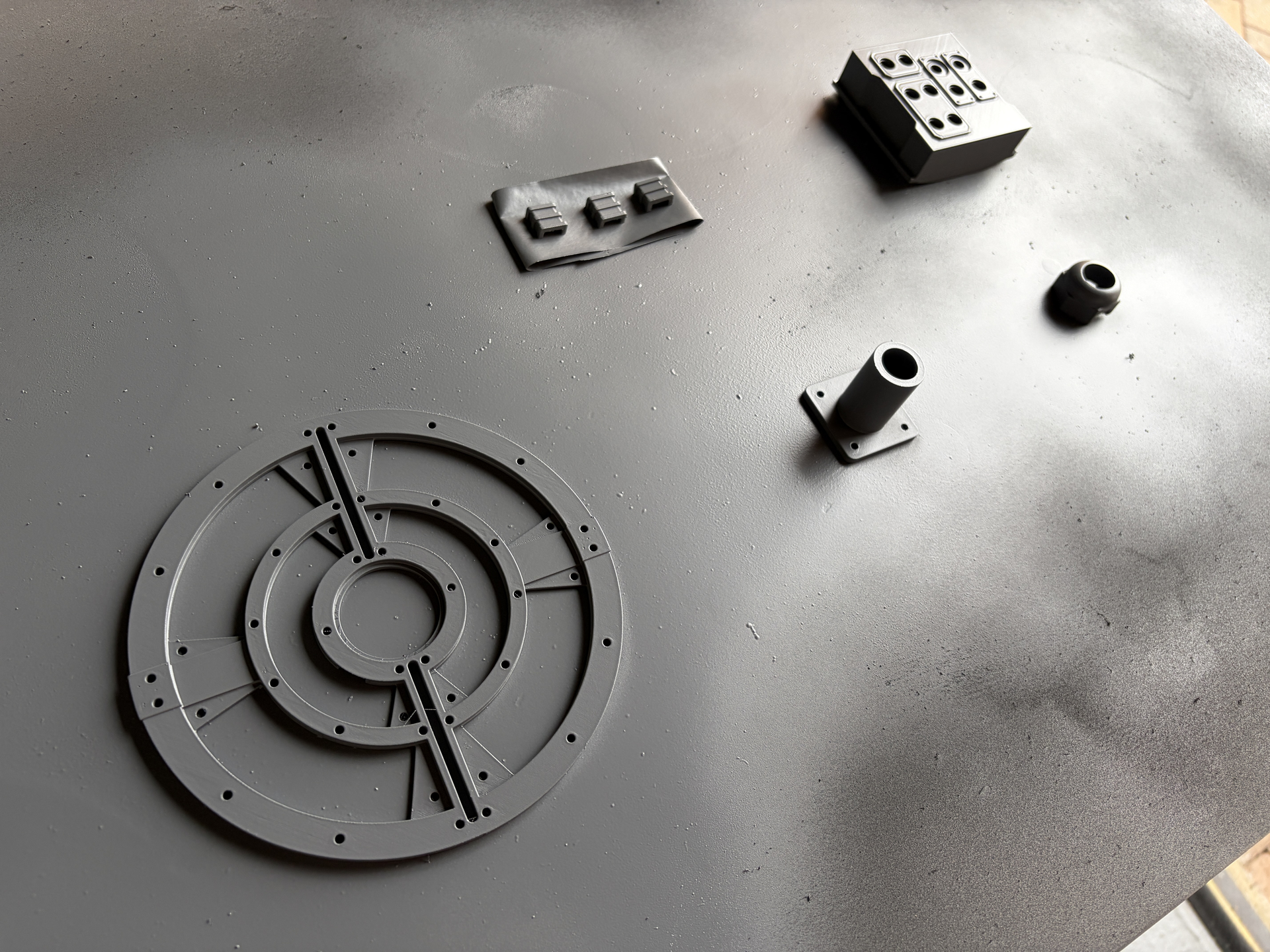
To paint everything, I’m going to start by using Jenolite Filler Primer. Earlier, when I painted the original injection moulded parts that came with the pack, I just used ordinary Jenolite Plastic Primer, which was fine for those parts, but I find that for 3D prints, especially where I want to do minimal sanding, the filler primer is much better.

It’s thicker than normal primer, obviously, so it fills in the gaps between the layer lines. Like most spray paints, it’s better to build up the layers with several even coats, as opposed to going in too ‘thick’ and trying to get rid of the layer lines in one or two coats. It’s self-levelling and pretty forgiving, but if you spray it on too thick, not only do you risk runs like any other spray paint, but you also risk losing some of the fine details, so you need to strike the right balance.

For these parts, I did around five even coats, with fifteen minutes between each coat to let the paint flash off.

What I really like about using the filler primer on 3D prints like this is that, as you spray it, you can literally see the layer lines being filled in and the surface starting to smooth. It doesn’t completely get rid of the layer lines, but it does enough for the later colour coats to finish the job:

Once the final colour coats have been applied, I think it’d be hard to tell that they’re 3D printed parts and not injection moulded ones, and the best part is that I’ve done hardly any sanding and no filling at all!

1 Like

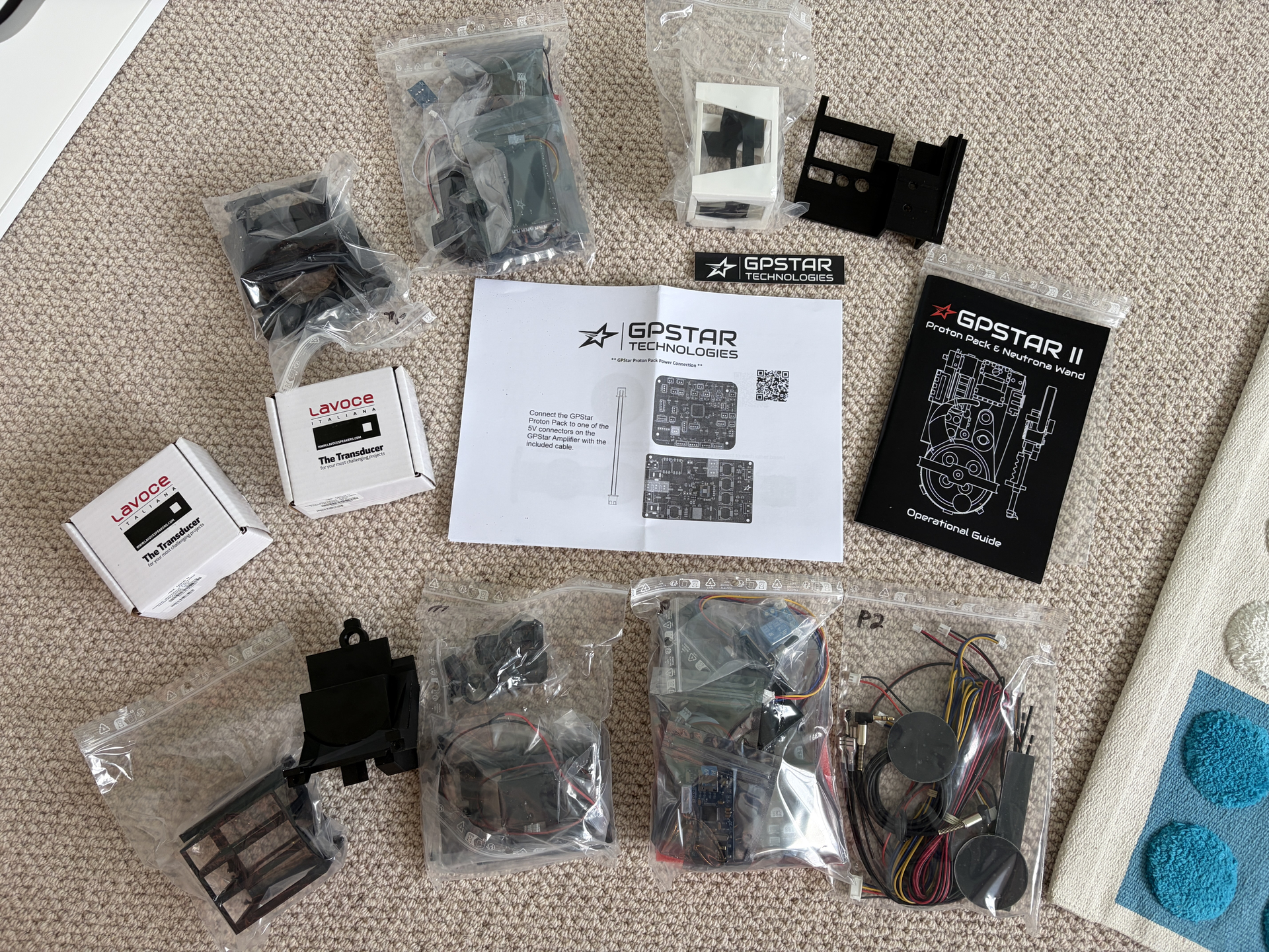
The GPStar base kit also arrived a few days ago, just need to figure out how this all goes into the pack and wand. Let’s hope I don’t need a degree in electrical engineering!

2 Likes

One of the GPStar devs here–if you run into an issue and need some help, feel free to reach out!

Also, buying a 3D Printer was 1000% the correct move. They’re freaking amazing machines nowadays, especially the Bambus. I have a P1S myself and I’m still getting used to the whole, “Man, I need…oh wait, I can just print it.”

Absolutely awesome being able to just print all your own stuff right at home in just a matter of hours.

Best of luck with the build!

Coming along great! The 3d printer really is clutch. I’ve printed a couple items for my build as well on my P1S. Specifically, replacing the PPD, Beamline, and Filler Tube has been a nice upgrade from the Hasbro stock pieces. Keep it coming!

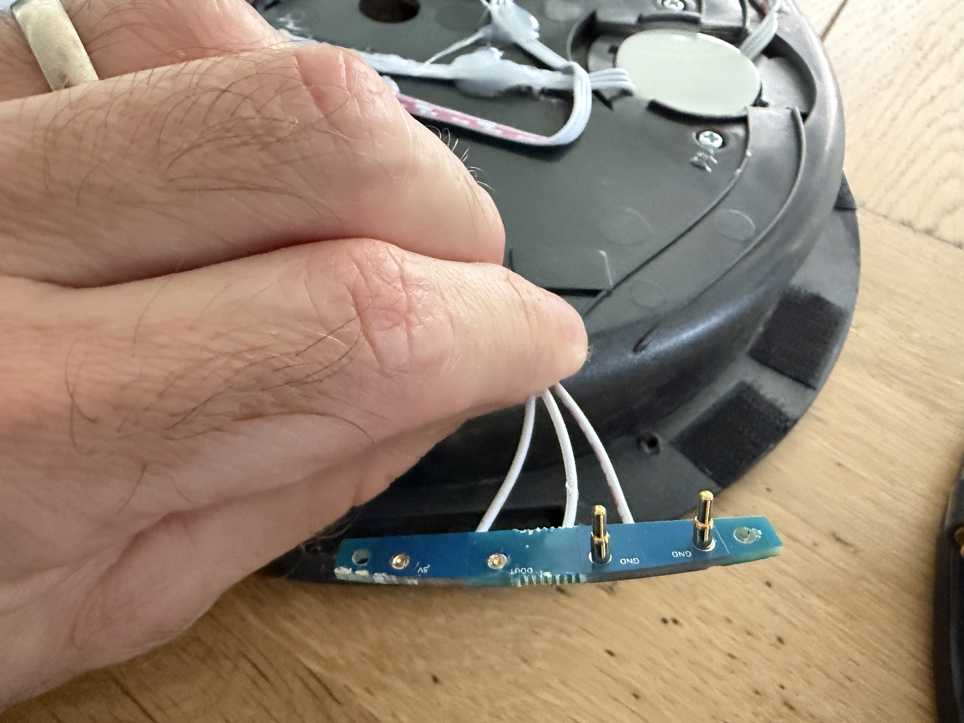
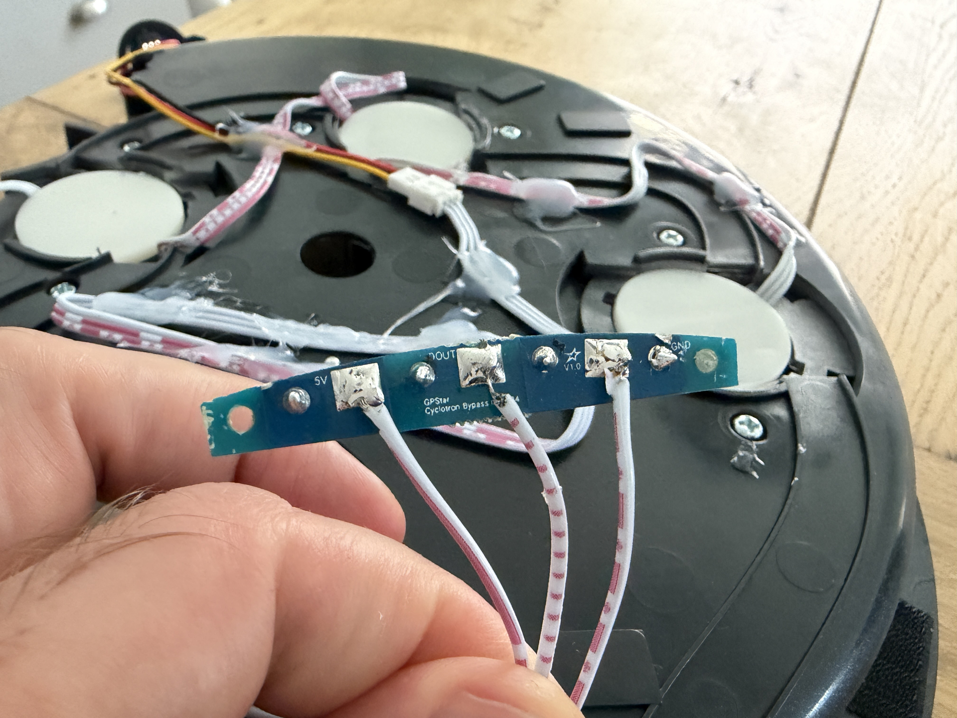
Hi @nomake-wan thanks! Actually yes I’ve had a pretty big issue! I got everything working on the pack fine, it was turning on fine, sounds coming out and the cyclotron lights were working fine, but then two of the pogo pins have snapped off the cyclotron bypass!

Do you guys do a replacement for this?

Apart from the above issue, thanks for the feedback guys! Yes having a 3D printer is pretty cool, I keep thinking of new things to print!

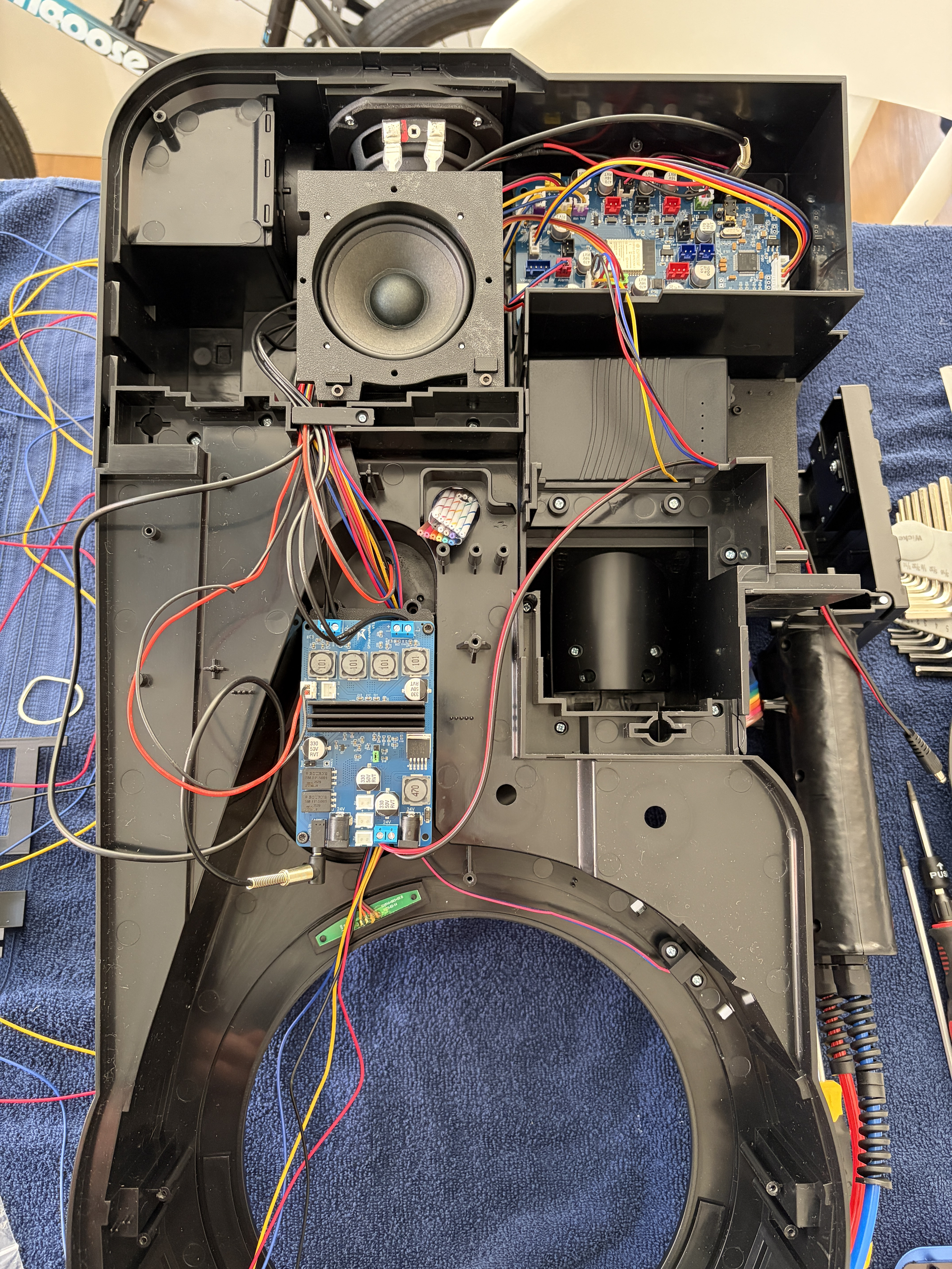
And apart from the issue with those pogo pins, the GPStar install went pretty well! Managed to get pretty much the whole pack done this weekend:

Also managed to get everything working, all the lights and sounds, it’s a really great kit. I’ll be moving onto the wand in a couple of weeks, just waiting for some other parts to arrive.

2 Likes

We do! Your parts have a two-year warranty on them, so that will be handled swiftly. Please reach out via the contact form here: Contact – GPStar Technologies

Make sure to include your order number as well for speedy service. The replacement parts usually ship out next day and should arrive to you within a week.

Sorry you ran into that, that’s definitely a weird one!