I recently got a micronotic 3001. Going to start a KUD build.
Does anybody know how to maintain the integrity of the electronics once removing the sense disc? I would like to have the needle jump and keep the sound… if not… static it is!
See if you can locate Dale Love. I know him via Facebook.
He just finished a KUD, and incorporate the guts of a different piece of tech used as a GB prop, the Realistic Sound Level Meter, so that the needle on the Micronta spikes in response to audio levels.
The microphone part goes right into the cut-off shaft of the metal detector, where you have to put some sort of cap anyway.
It is genius and awesome! I just saw a vid of it on FB this morning.
If you’re planning to gut a Sound Level Meter anyway to put the movie sound effects in it, as Dave An has done, might as well make use of the leftover internals, right?
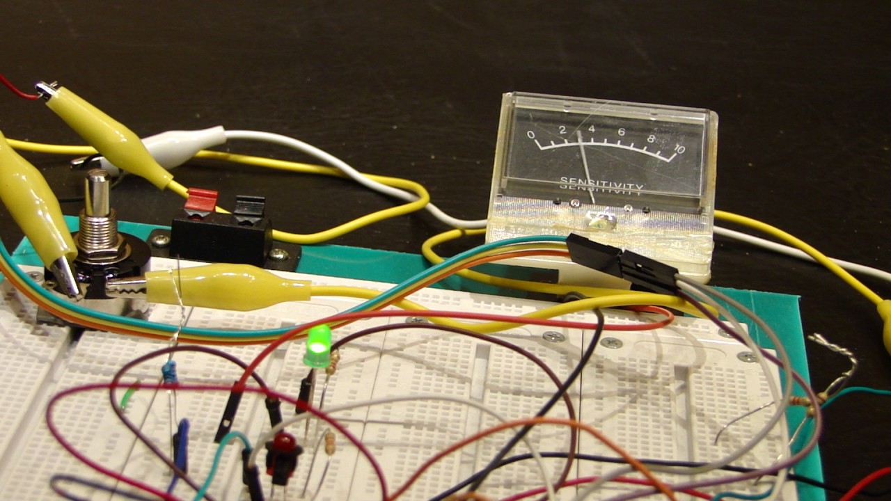
I’m working on one now. I’m still at breadboard but I want it to do more than just flash leds. What I’m trying to accomplish is multiple sounds, selected with a rotary switch, which will fluctuate the gauge and have another rotary switch for volume control. Maybe even a motion/heat/proximity sensor in front, which would act like the metal detector and make sounds and move the gauge when you approach subjects. Perhaps even ion detection…. we have these large kitchen utensils mounted if front…might as well find a use for them!! Still have a ways to go though…
it’s all done with coding through an Arduino at the moment. I’m new to this so it’s like learning a new language. I get one thing to work and then another thing fails. You think you’re close, then you add something new and you’re back to step one again. I’ll get it eventually and hope to have a prototype soon.
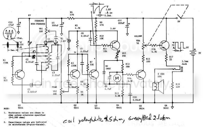
the sound module I have doesn’t come with a built in amplifier so I had the choice of a 2 watt or 3 watt with a gain adjustment. Also the one I chose had enough outputs for the switches that I had around in my box of parts. Plus the device that I used was a drag and drop so no files had to be programmed just re-named so it would play. It’s the PAM8302 and 2341 audio effects board from adafruit. for my limited information and programming abilities this is what was best for me. I have extra rotary switches and spacers that make them work with the original knobs if your interested. Also I know you said that you were still programming and working the bugs out of your needle setup but what parts did you use that you had to program, and was some of the parts a sound activated trigger module? How did you figure out how to make the needle move was it voltage, resistance, where is this info? I only ask since mine is still in standby mode and I would like to finish mine up as well as maybe I can help dial both of ours in. I have the original wiring schematic but it leaves some things out.
Here’s the set-up I’m using right now. It works really well, but because I’m using a microphone through a micro-controller to pick up the sounds from the speaker, when I turn the volume down low I get little to no movement from the gauge.
I’m working on a solution now to eliminate the microphone.
I really like the idea of different color lighting for the gauge and would like for the color to change automatically. Like when the gauge hits 10 it’ll turn red. Maybe even coordinate the blinking red led to increase its speed as the gauge goes higher. Man, I just keep adding things!
The Gauge is a mA gauge.
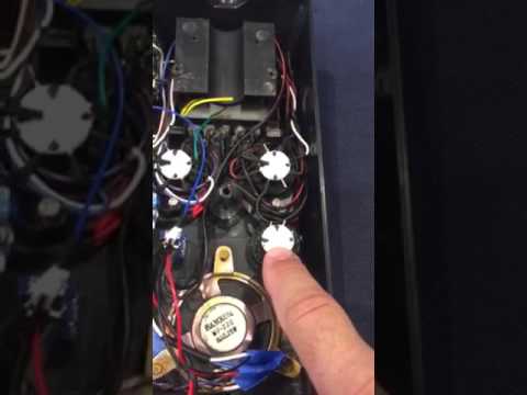
I’m actually using phenolic perfboard to replace the PCB so I can attach the switches the same way they were originally.
I haven’t got that far yet. The skimmer looks to be just cutting a slot in the tube and the skimmer could be held in place by packing some epoxy putty in there. The potato masher seems to be installed different ways. Some people cut a slot in the body and mount it internally. It does seem to be cleaner, but the original appears to be mounted outside the body with the end bent down and attached with 2 screws. Stainless is a pain to drill so that may be why people go for the former.
Wow thank you so much for the info, I can’t believe it’s as simple as a Ma gauge. How did you figure that out? I’m loving the idea of the multicolored led changing based on the level of the meter I can’t wait to see that. I can’t wait to see the progress pictures of the PCB and the rest of what you have. Let me know if you need an led holder printed I have an extra one I can modify. With my limited amount of programming knowledge I have seen a code from adafruit of a board that responds to sound via led like a meter, but I’m not sure if you could add that code to the one that you wrote and have them work together. I’ll post as soon as I find the link.
Would you be willing to share the code, the devices and how you hooked up to the meter like which wire was connected to the arduino and what was the other one hooked up to?