My 'Idealized' Shell Build

Last year my brother came to me with a dilemma. He was unfortunate enough to have purchased a shell from Video Bob several years ago and from the moment it arrived he was unhappy with not only the quality of the casting, but also with the distortion found all throughout the shell. The biggest issue was the cyclotron. It sloped toward the center of the shell as if it was crushed down into the shell prior to molding giving it a near irreparable taper. The gear box was also a problem as it sloped toward the power cell. His question was what it would take to salvage it and make it a presentable shell. Weighing the issues, I determined it would be easier to just start over. Included in the box that his shell came in was a document claiming it was a descendant of a shell used at a Universal Studios show. With how incredibly poor the shell was, we doubted the validity of his claim.

After obtaining many high resolution photos from a member of this forum and using the photos in the reference section on this site, we compared the Video Bob shell to shells at the Sony Studios lobby and at several Planet Hollywood locations. We concluded that the upper half of the shell was indeed a copy of an original albeit a highly degraded copy. The bottom section of the shell was perplexing as it contained features (read errors) that aren’t found on the original shells. The S shaped valley between the synchronous generator and PPD was very narrow. Our beam line and filler tube mock ups would not fit properly, there simply wasn’t enough space. The Clippard valve mounting base was out of round and the small ring at its base was off center and tapered. Lastly the cyclotron rings were quite out of round and the holes drilled in them were not centered and not all the same diameter.

As we confirmed that the upper half was at least marginally accurate, I took measurements to consider as possible reference then set the shell aside and began work on an original shell.

When seeing the pack prop in the film, an immediate idea was formed as to how that object would look if it were a real, operable device. The photo reference material reveals what I believe to be errors in construction of the original master. For example, the fins on the boxes are placed at non-equidistant intervals appearing to have been eyeballed as to their spacing. We decided our effort at making a shell would present it with these issues resolved resulting in a shell as one would imagine it to appear if it were a factory manufactured piece for a real life Proton Pack. I took the job of research and fabrication while my brother made all molds of the masters I created.

What follows are images chronicling the construction process.
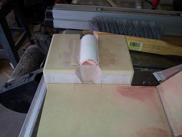
I started at the top of the shell first and created each box individually before attaching them together and blending the seams. The PVC tube is the exact O.D. and I.D. of the respective part on the gear box found on the VB shell. That is the extent of the VB shell influence on this shell.
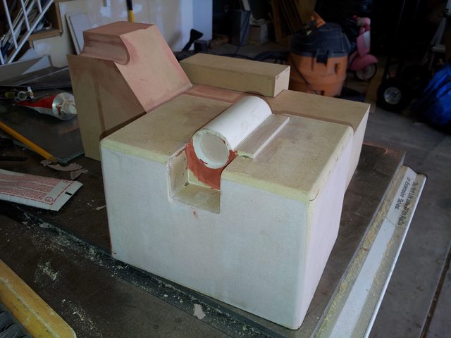
This shows the taper of the gear box.
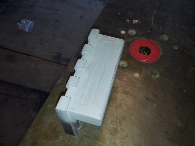
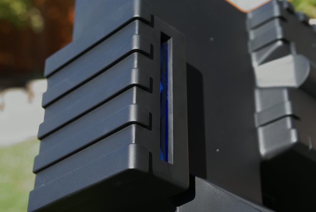
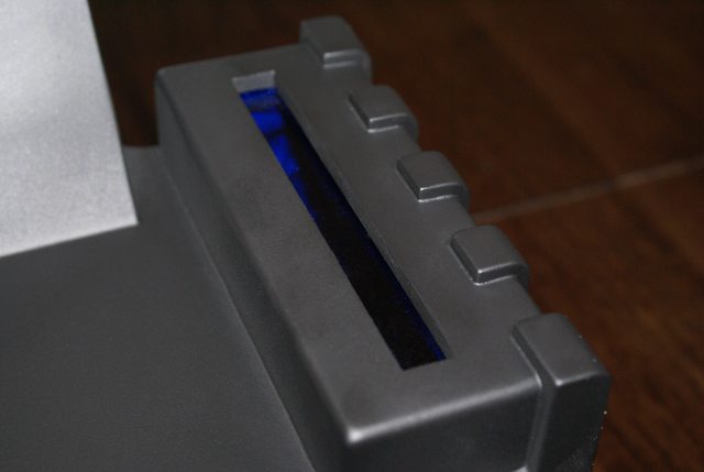
The power cell with an early concept of the opening for the blue plastic lens.
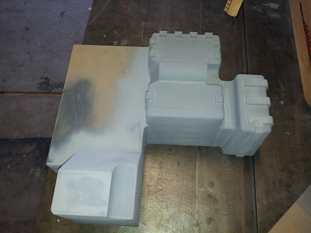
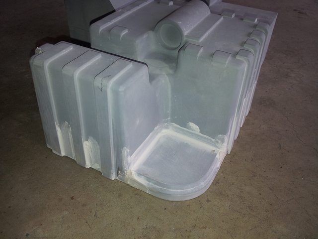
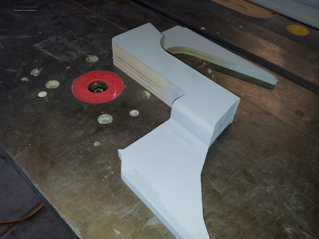
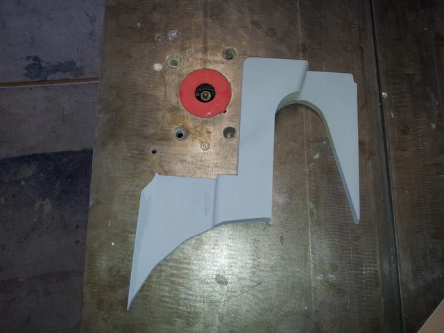
The S shaped valley.
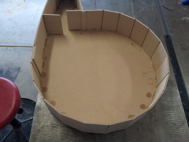
The inside of the Synchronous Generator. The arm has a curve that we thought was correct at this stage, but is corrected later to be flat.
Another view of the incorrect curve.
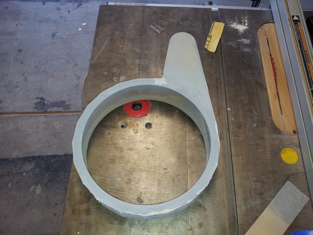
The Synchronous Generator with the corrected arm.
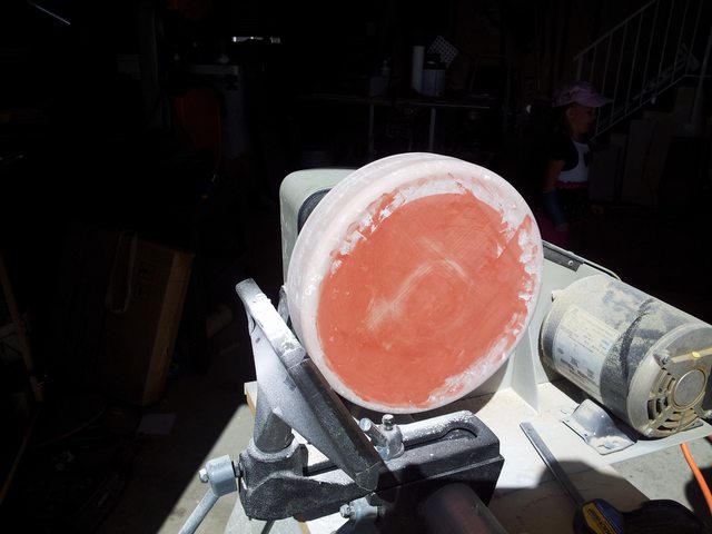
The Cyclotron I turned on my wood lathe.
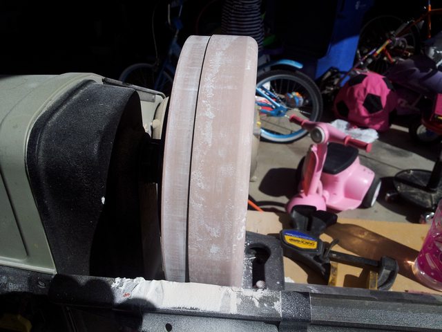
The Cyclotron again, I made a metal template that was used to evenly spread Bondo around the MDF core to get the correct curvature and a square side and also to create a step that mates with the ring that mates with the Synchronous Generator.

The Cyclotron on the Synchronous Generator, again prior to correcting the curvature in the arm.
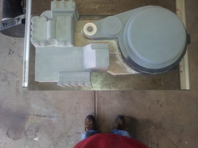
All pieces in place prior to being glued together.

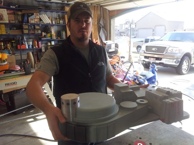
My brother. Visible is an aluminum mock up of the N filter.
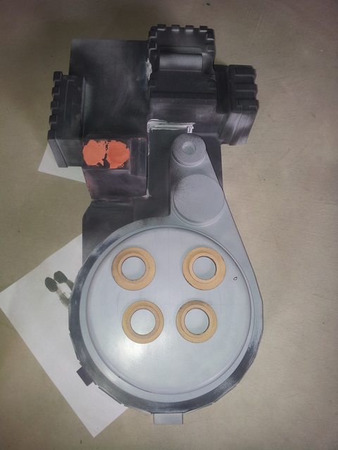
Cyclotron with the beginnings of the Cyclotron Rings.
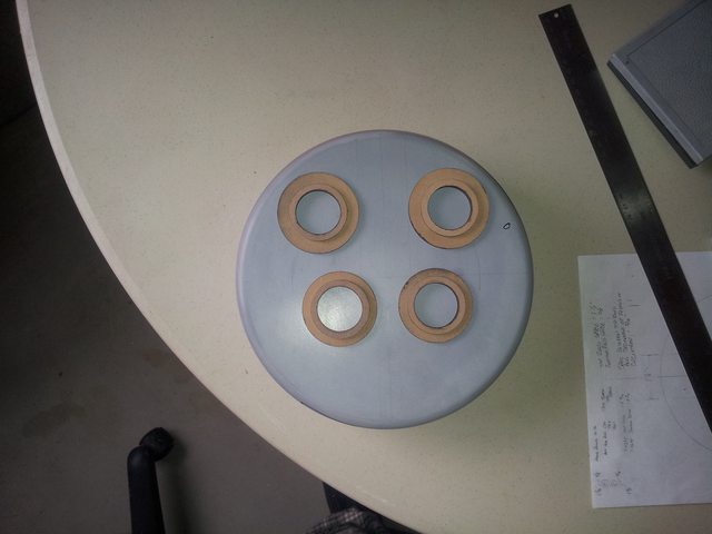
Marking the Cyclotron for Cyclotron Ring placement.
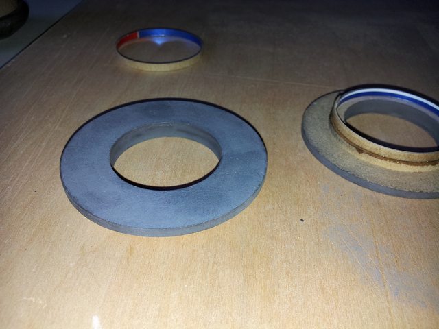
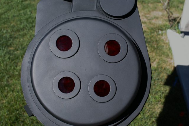
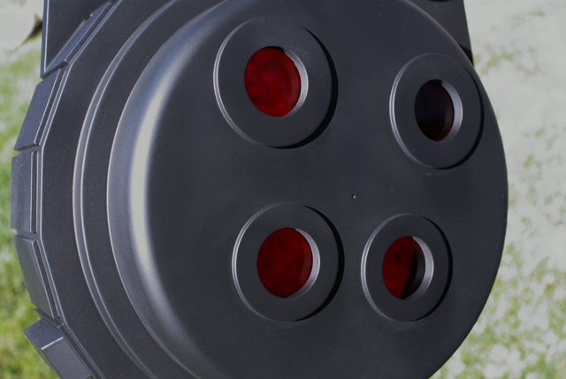
I made the Cyclotron Rings in such a way that when the cast is pulled from the mold, there is only a thin amount of material to remove from the inside of the shell, resulting a controlled and proper thickness of shell material where the lens mounts. More on this later…

The Cyclotron drilled to receive the Rings.
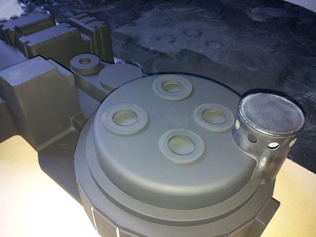
The N Filter in place for reference, but it was not part of the mold. It was molded separately.
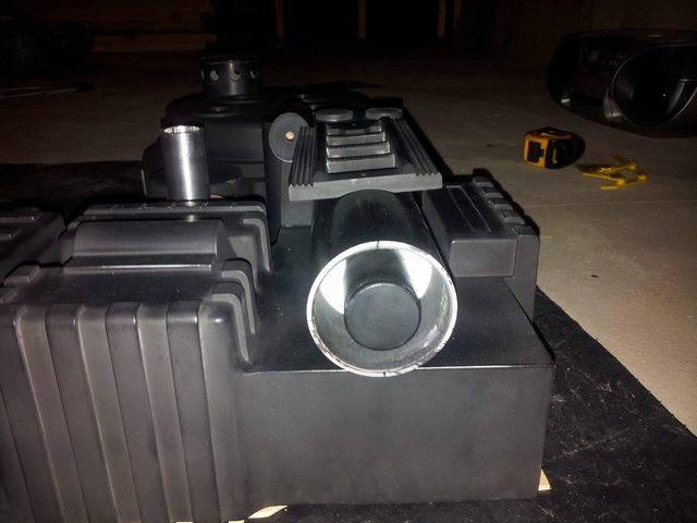
Checking the fit of various components also all made my me. I will cover those later in the post.

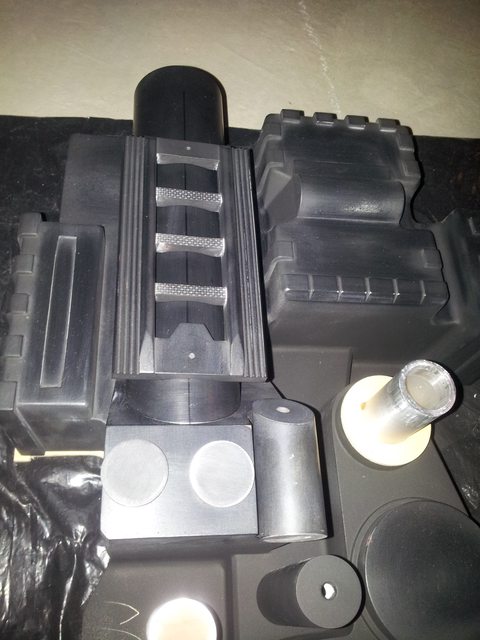
Next…the mold…
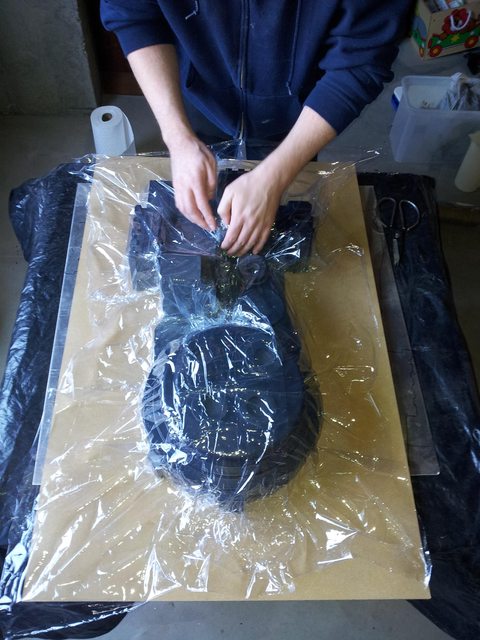
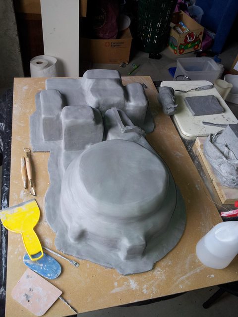
Since we covered the MDF master with a water based clay, the master was covered with plastic wrap to protect it from moisture.

The master covered in clay. This clay creates the space that later will be occupied by silicone.

More to come…

I had two duplicates in my first post, the correct pictures should be these:

One more I just caught…

Superb scratch-building work, it’s understandable why your shell was initially mistaken for one of the descendants of the HMS/Boss Studios pulls.

How easy or difficult did you find it adding the curve to the Booster Frame?

Clean build…

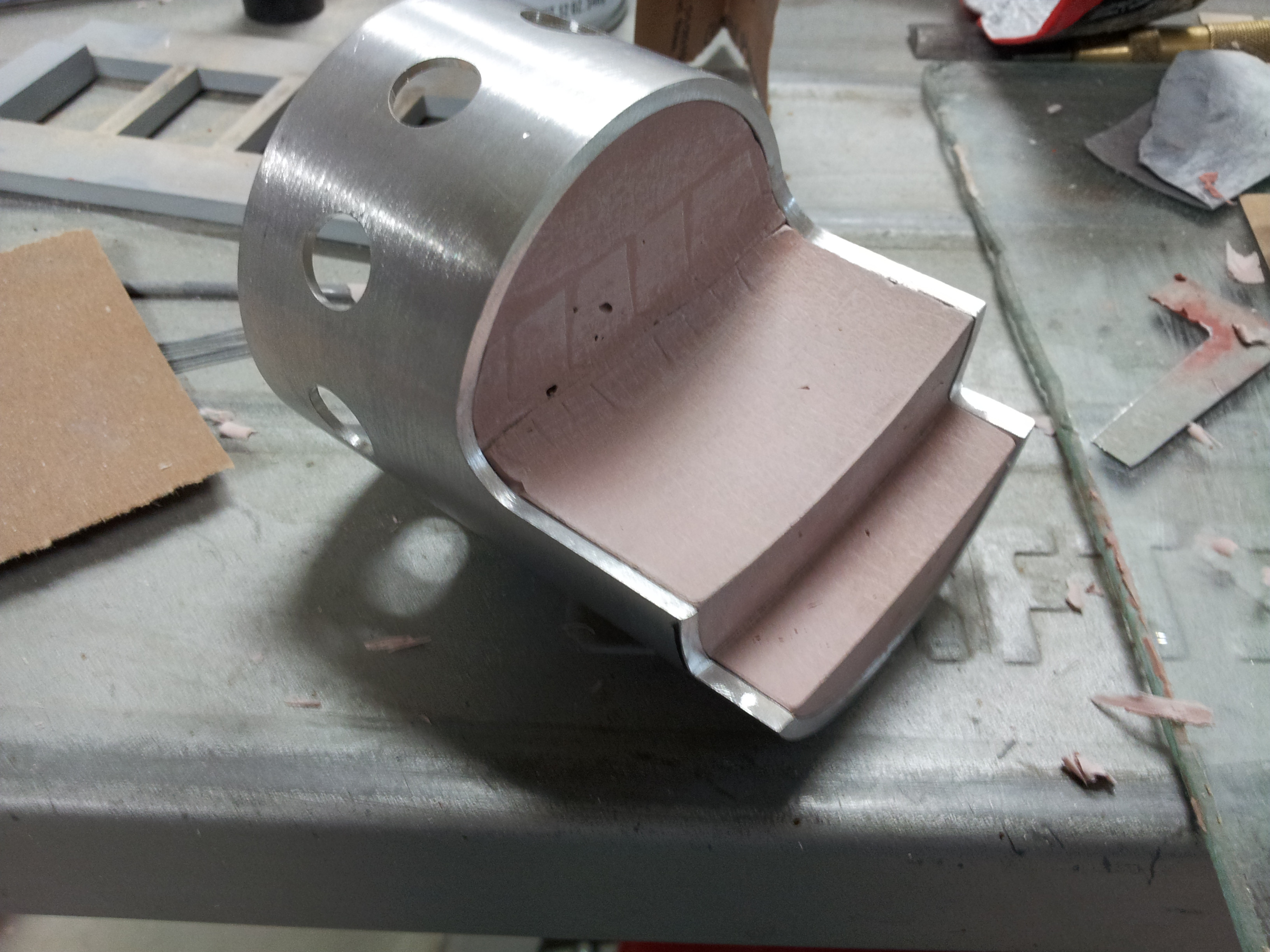
Kingpin, Thank you, images of the completed shell are coming… The curve wasn’t difficult. After looking at many different photos and extrapolating measurents, the width of the curve was marked on the underside making sure it was centered. Then the depth was marked on the sides of the ‘rungs’. Then a piece of aluminum tube of the same diameter as the booster tube was covered with sand paper and a curve was sanded into the bottom until it reached the measurement marks made.

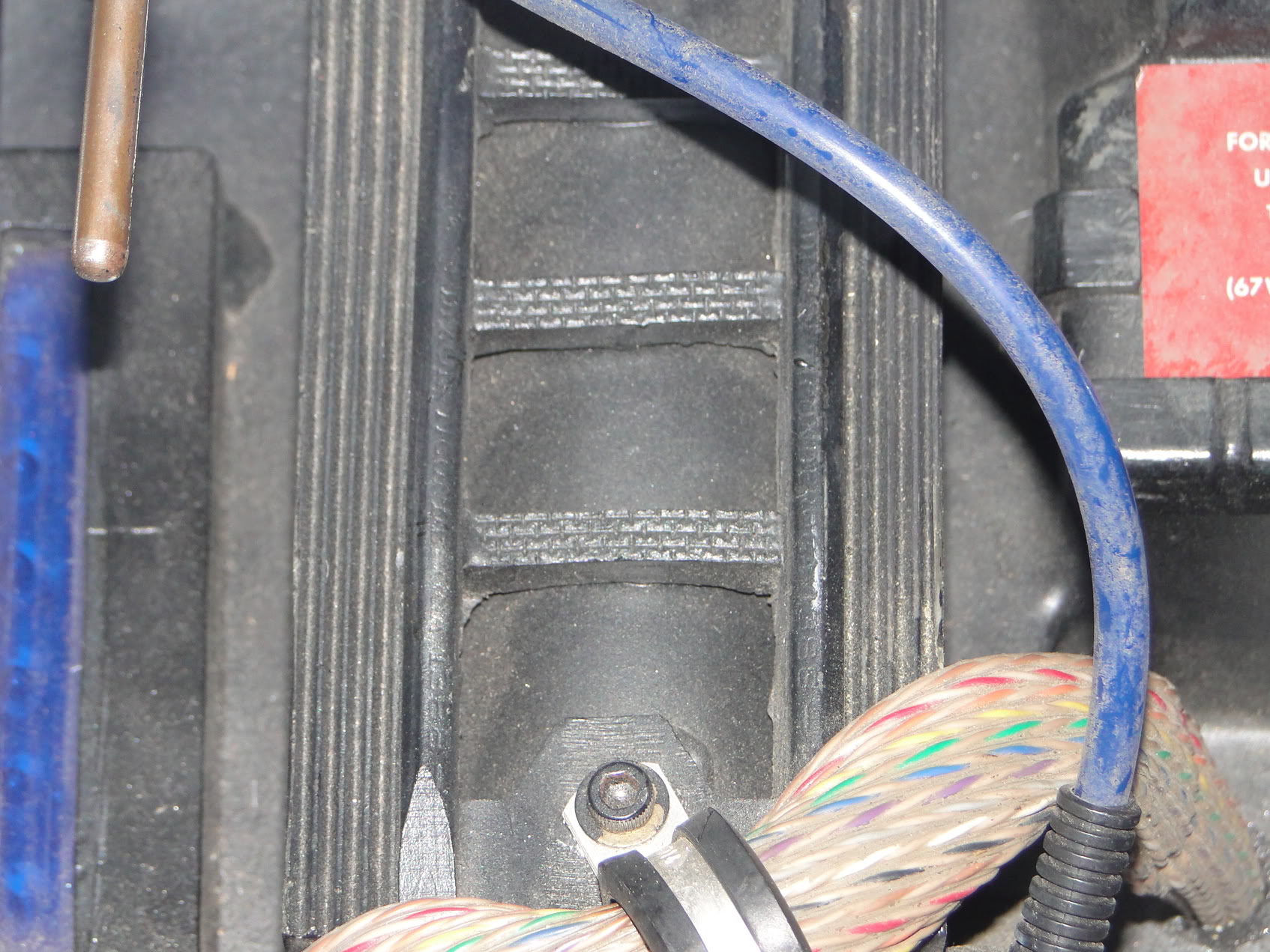
The pencils on the sides are Dixon Ticonderogas, but as this is ‘idealized’, the lettering was hidden. The corrugated sides are was is used as mold wall or “dam wall” in mold making. A strip of this material was given to my brother and I think it is actually what was used rather than the rubber mat. The ‘rungs’ are MDF with masonite on top that had the proper ‘brick’ pattern which is actually made by the screen that the material rests on during manufacture which leaves that imprint similar to how the bottom of a Snickers bar has that wavy pattern.

This might have been mentioned before, but look at this image:

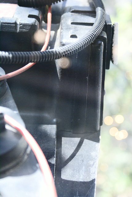
The top and bottom of the booster frame show the curvature on the wrong side of the frame. The sanding marks are visible but must have been made with a drum sander rather than the method I used as the marks run in the opposite direction.

Really nice work replicating all the features, and a very clean build if I say so myself.

The only note id add if you were ever thinking about remoulding the shell is the cyclotron holes are a bit too large for me. All the hero packs hard varying sizes of holes and the Murrary and spengler pack holes were alot smaller than your current ones, it might be nice to have the option to decide what pack your shooting for…

But… seriously nice work and attention to detail.

Very nice indeed!

Julz,

That is a good idea, these rings were made according to measurements of the hero pack in the Sony Lobby. I do plan to make the rings available as a separate mold, I will look into the different sizes you mention :slight_smile:

Well done sir! Glad to see t he process of your build!

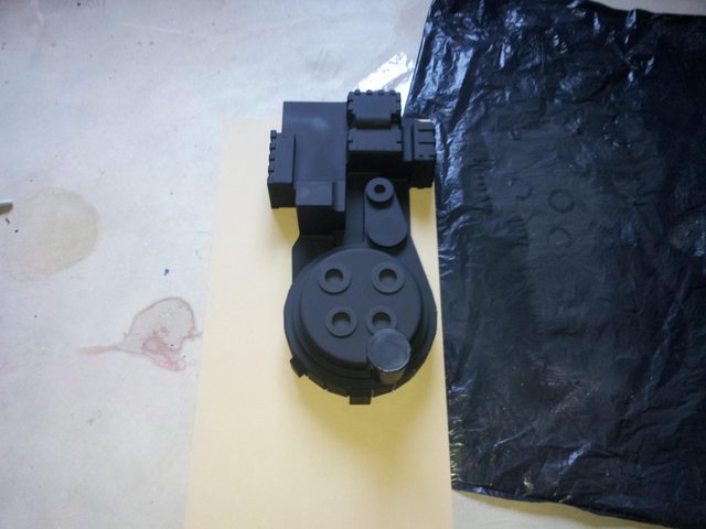
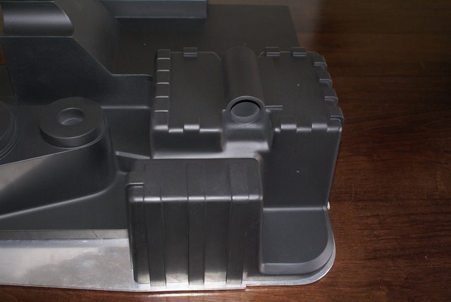
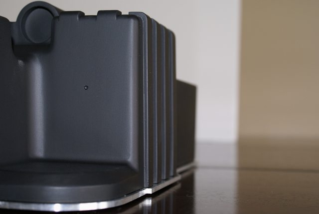
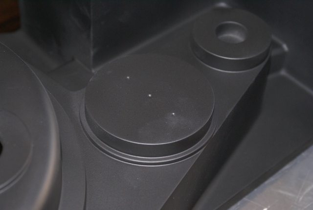
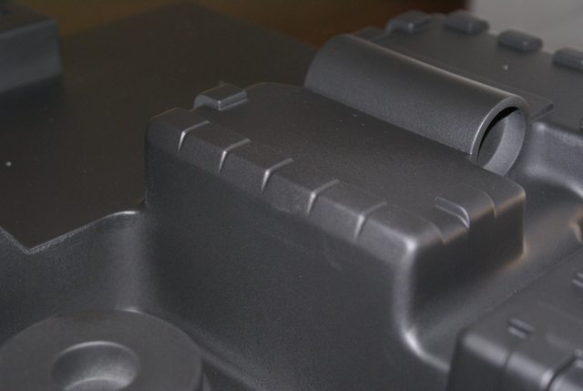
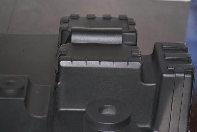
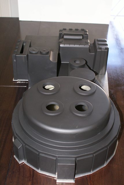
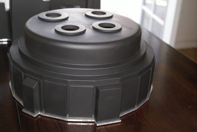
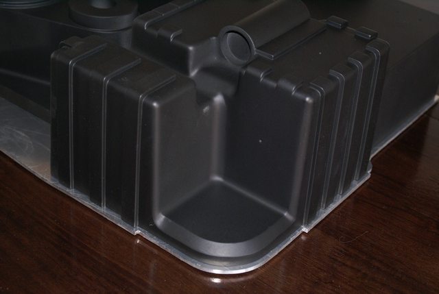
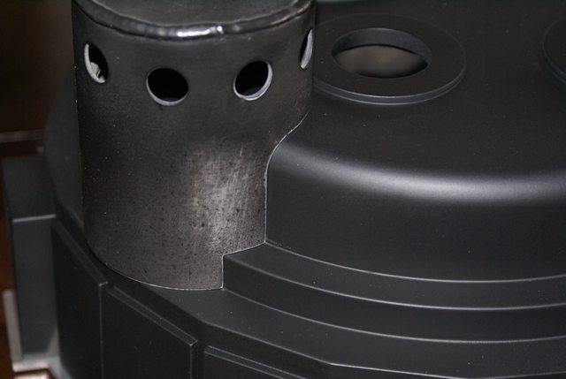
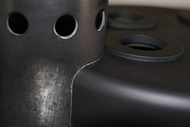
Here are some images of the completed shell.

The N-Filter is molded separately and mounts with a special base so it is removable (see below) if needed.

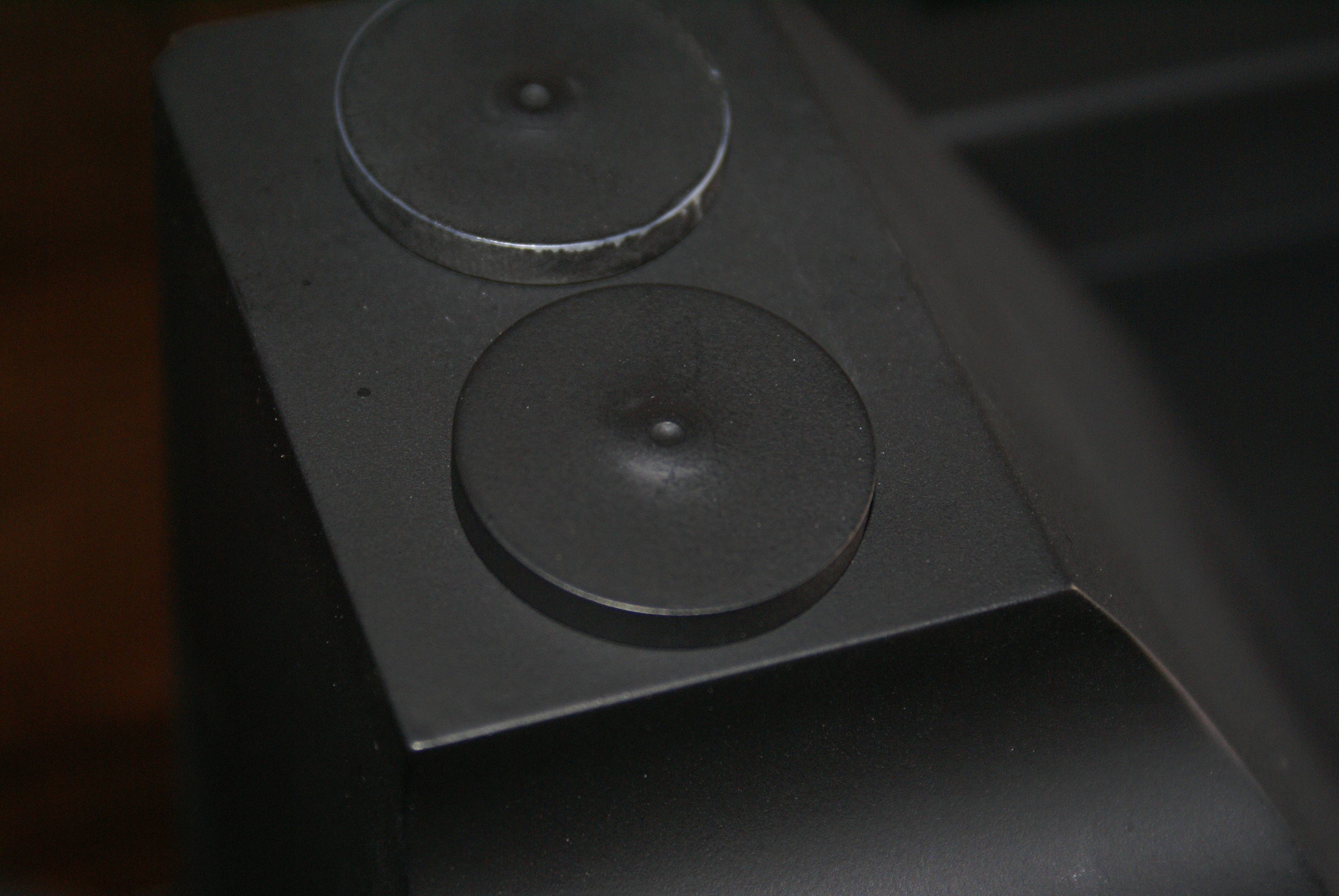
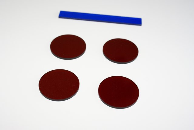
The lenses for the Power Cell and Cyclotron are round and drop into recesses created at the time of molding which creates a completely flat and equally thick surface for each lens.

The gun mount compared with the gun mount on a pack at the Sony Studios lobby.

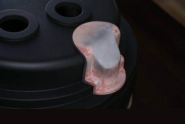
The N-Filter Aluminum master showing how it mates with the Cyclotron.

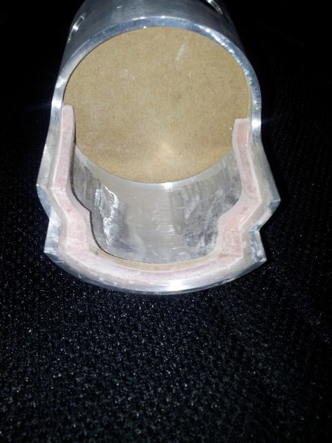
The master is a 1/8" thick, 3" diameter tube that was turned down to 1/6" where the 1/2" diameter circles are drilled. These are placed equidistant from one another rather than the eyeballed placement on the originals.

The master for the piece that mounts onto the Cyclotron and into the N-filter.

The inside of the master showing the positive mate surface for the N-filter mount.

The assembly before final finishing.

Mother of god, that thing is immaculate. I’m speechless.

Yeah, that’s a pretty clean cast.

Beautiful work sir!

Amazing job!

Any plans on the next mold to add the texturing?

I’m gonna have to go walk this one off. Nice work.

I got to see a pull from this mold a couple weeks back at at barbeque with Larz’s brother, and I have to say, I could only make farrell grunting sounds upon seeing it for the first time.

wow, what a thing of beauty, nice job!

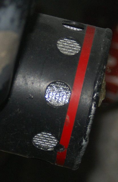
I have seen several packs/posts where the N-filter has been filled with steel wool or some other fibrous material. In this photo it does appear to go as follows:

Screen

Plastic

Steel wool

However, in this photo you can see right through the filter…

In person you can clearly see that it is a screen over what appears to be saran wrap or some other thin plastic film that has been crushed or crinkled up then flattened back out and installed. I was able to see easily through the filter with nothing inside. I am unaware if there was indeed steel wool in them at one time, but if this N-filter has not been altered since filming, then there isn’t anything there except screen and plastic.

AJ,

The topic of texturizing came up a lot during the fabrication of this shell. We left the surface smooth in this run because we toyed with the idea of offering a pre-painted/distressed (weathered or aged) shell done in a way that appears like chipped paint over aluminum rather than the dry brushed effect. This run was to offer a shell that is completely smooth as one imagines the shell to appear before seeing a real pack, that way a person interested in this shell could have the option of either surface. There will be a second mold made when the current mold no longer produces good casts so that mold may very well include the texture.