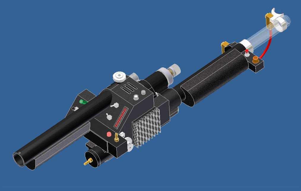
I’ve been working on modelling the Thrower in AutoDesk Inventor for several weeks in order to have more reliable plans to work from in creating my actual real world gun.
Of note, there are some parts that I know are “perfect” and some that are nearly so. The Clippard R-701 and the 11752-1 are perfect, since they were modeled from CAD drawings provided by Clippard. (I just turned them into 3-D.)
The Cliplites should be essentially right, since I have some. The only issue there is if it’s really the correct part.
All other drawings were created using Stefan’s plans as a starting point. I then compared the resulting 3-D model to the reference images I had available to me. When I wasn’t happy with something, I tweaked that part a bit.
I’m still not 100% happy with this, and obviously have a few more parts to add. Here’s where you come in. I want you to tell me what I got wrong on this. I’m sure I’ll get at least a few of you to offer constructive criticism. I want to make this as close to the real deal as I can. (Please note that I haven’t figured out how to add the welds yet.)
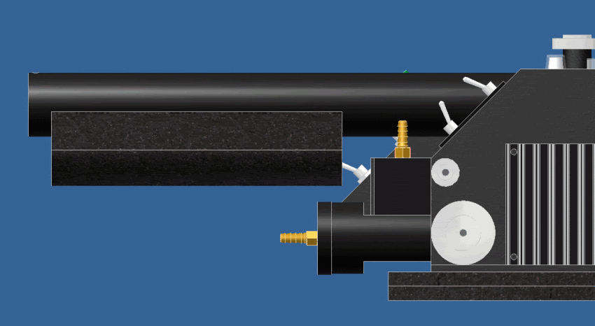
So, here’s a few progress images. If you click on them, you’ll get a chance to see them larger.
At some point, I’ll probably try to pose my model in similar angles as some of the PH reference images, and show them side by side for improved comparison.
I purposely used slightly different textures on some of the parts to make it easier to see them next to each other.
Me too, that’s why I’m doing this! I have asked for some general size recommendations, and have gotten the helpful suggestion to start with Stefan’s plans and to modify them to look more screen accurate. :sigh:
I’ve personally spent more than 100 hours working on this thus far.
So nitpickers, I know you’re out there. Tell me what’s wrong with it… :walterpeck:
That is a great looking model! Depending on how ■■■■ you would like to get with you the only things i see that would need some tweeking are some of the edges. i.e. the edge of where the front plate (with the barrel and front cylinder) and the plate running perpendicular (plate with white hat light) meet. That edge is not a sharp edge but rather a bent edge from a single plate.
Overall it’s a fantastic model and I think you have included all the key features minus the set screw Austin listed above.
Thanks for the kind words, Kingpin. I’m kind of new to Inventor, so I’m really not sure if it’s possible to create the various knurls found on the knobs. If it’s something vertical, more of a spline, I can draw it in AutoCAD then extrude it, but cross-hatch type patterns are a lot more complicated.
Take a look at my Cliplite drawing for an idea on the vertical groove thing.
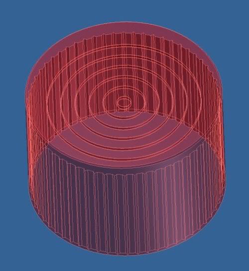
If you look at it closely, you’ll notice that it’s really not exactly how the Cliplites look, but it’s fairly close. I created it by extruding a drawing of the main shell cross-section, which has the grooves on the inside. I then created another extrusion to represent the rings on the top and a final extrusion to create a flat surface to the top. If I change the material to something other than a transparent color, the whole thing just looks like a solid cylinder with a tiny chamfer to the top edge.
Here’s a teaser update on my virtual progress. I have a few more changes to implement, but here’s an image or two to look at. Yeah, I know the grips aren’t supposed to be solid like that. These are just placeholders for better models I’m working on.
My tubing is 1 1/8", but I’m thinking it should perhaps be 1 1/4". Thoughts?
The tubing for the handles should have an OD of 1.25". Also the rear grip should have about 1/2" space between it and the rear instrument bar. In the one picture you provided, it looks to be flush with the rear instrument bar.
I still need to update my tubing to 1.25" It’ll impact my grips the most, as far as modelling goes, so I’m glad I hadn’t perfected the grip shape yet.
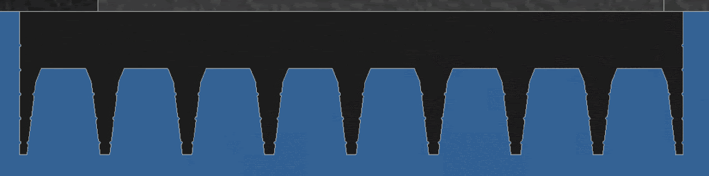
I suspect there’s a thread out there discussing the grooves (and size) of the heatsink as well. Any handy links for that? I’m personally convinced that the vanes are nearly so wavy as some of the replicas I’ve seen made. Want to shoot me down on that?
The distance between the grip and the rear instrument bar looks much better. Just need to change the OD of the handles now
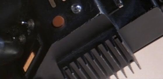
Here is a thread that someone was trying to get the profile for the heatsink figured out and Namebrand helped him out: link
No measurement’s but you can see the profile of the heatsink atleast.
Also, is there a chance we could see the front handle assembly a little better? It should consist of 2 tubes: and inner tube, unpainted; and a outer tube, painted black with the “ears”, grip, and grip lock on it. To me in your one picture, it looks like you just have one tube, that is fitted inside the “stem” coming out of the gun body, with the tip of it not painted.
You can see some of the “inner tube” exposed here between the “stem” and the grip lock in this picture:
And again here, at the tip of the gun:
So the I feel the “outer” tube should be the same OD as the “stem” coming out of the gun box that the handle is mounted into. This 2 tube system is why the front grip could rotate. The outer tube rotated around the inner tube.
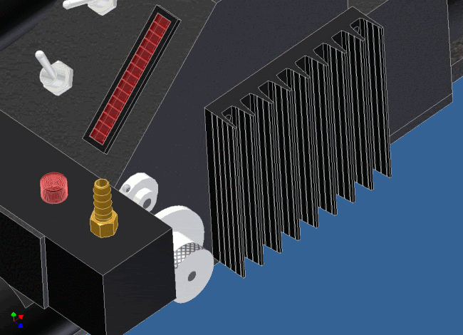
Ok, now for another question. I’ve been trying to work out how deep the grooves on the heatsink are as well as the “real” dimensions of it. Based on numerous reference images, I really think this is close.
Yes, you’re quite right. I had modelled this as a single tube. It makes total sense that it should be 2, for the rotation, if nothing else. And you are correct, it is visible in the reference images you show. I didn’t look at those enough when I created that part of my gun, obviously… Of course, this means I have to update more of it before I post clearer images of the front. Seriously though, this is the type of input I find highly valuable. Thanks for making this better.
That’s the profile of the heatsink that I’m not so sure is correct. I know that Exoray had made some a while back that didn’t have the wavy look to them, then it would seem later he did, based on the namebrand design.
I guess I was hoping for some clarification as to why the switch to the wavy format. If there’s good evidence of it, then I’ll gratefully absorb the info and change accordingly. But I haven’t really seen anything that shows this look clearly. Based on all other heat sinks and aluminum extrusions I’ve seen, I haven’t seen anything like this.
(Or is this a case of “we have good evidence, but can’t share it, just trust us”?) I can probably even live with that if this is the case…
The only 2 people that I would trust with the profile of the fins on the heatsink would be namebrand and exoray. I would honestly contact them and see what they say.