Very clever!!
Now things get easy! I know there are examples of the various configurations for the daughter board. But my take was to jam as many components on the board as possible, just because it’s cool. And more parts means better!
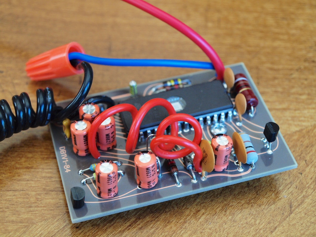

After adding a bit of soft Velcro to the back to protect my belt from solder mount scratches, I superglued the shaver cord to the main board.
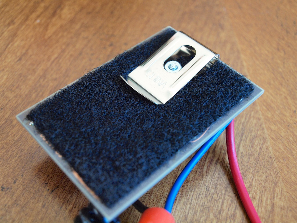
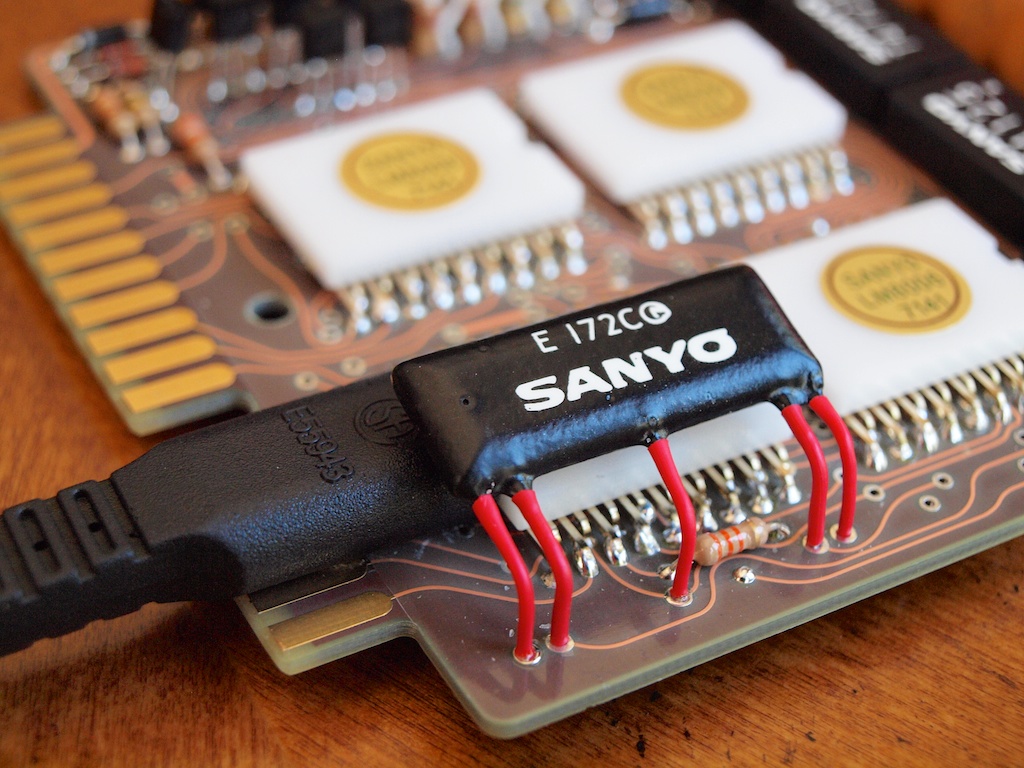
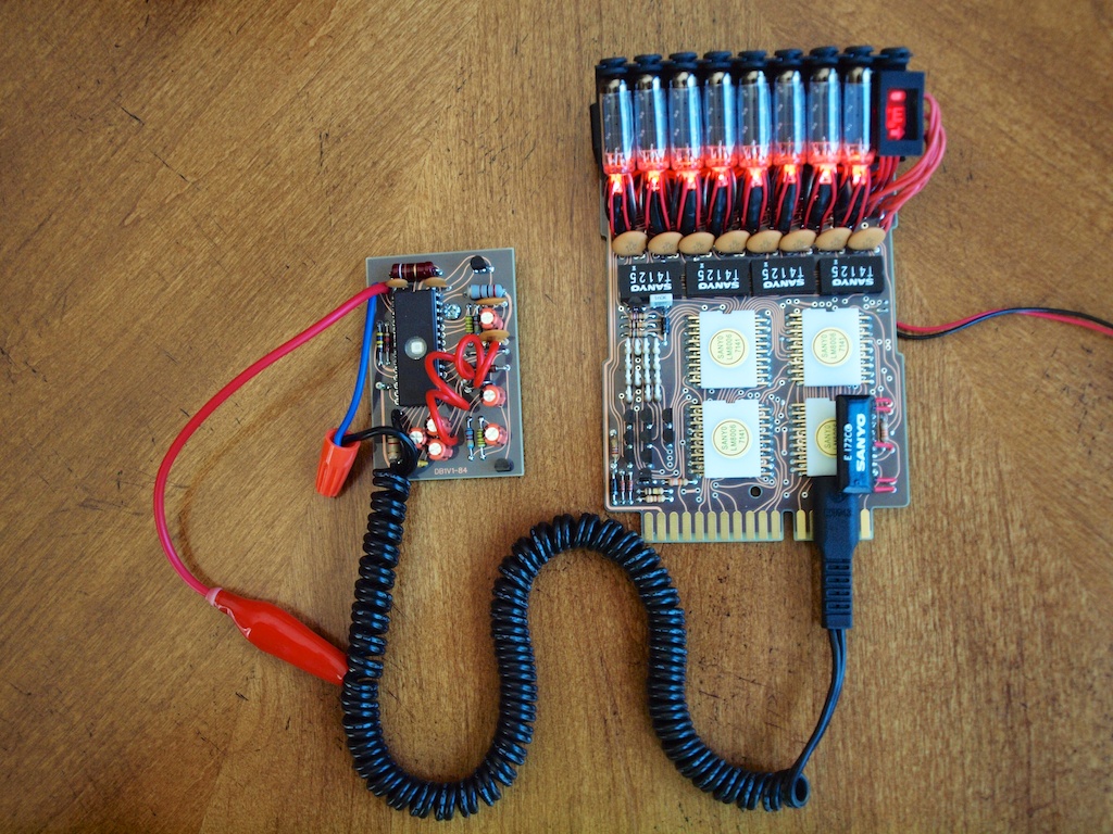
And here it is, the completed Belt Gizmo. I’d like to thank Spongeface for offering such a great kit to the community. Challenge and fun all rolled into one package!
Nice idea with the fuzzy velcro… I’ll have to steal that idea… =P
The Velcro is brilliant! I hate trying to take off and put on the DB because it gets snagged. Will steal that idea!
Good job you did on the gizmo!
Thanks guys. Make sure you get the “industrial strength” variety. Sticks nicely!
Honestly, that’s the only kind I got!
Wow! This is great!
Great build, bishop! 
Out of curiosity did you do anything special when soldering your shaver cord to the daughter board? I had my wires snap at the daughter board and am looking for any ideas how to reinforce it when I reattach it.
Yes, I did three things to minimize the possibility of breaking.
First, pre-solder the ends of the wire. It is important to properly heat the wire as the solder is applied so some is transferred up into and under the plastic sheath while not letting the plastic melt beyond getting a bit soft. Exposed stranded wire is very weak and the goal here is to create a small section of solid wire that extends up into the sheath. This is the most important preventative measure.
Second, hold the plastic sheath flat against the board as it is soldered and when it gets soft from the heat, push it down slightly and hold steady as the solder hardens. This will help reduce any gap between the wire and the board which will allow movement and eventual failure.
Third, and only if you are confident in your superglue skills, place a small amount on a toothpick, gently pull up one edge of the plastic sheath and glue to the board. You don’t need much and you don’t need to glue all the way around, just enough in one place to keep the plastic sheath attached.
Hope this helps. Let me know how it works out.
Awesome job and great additional info!
I did order some gold finger nail pin striping tape from ebay (maybe able to get some local but I am lazy and it was only a $1 shipped?!?) and added the gold trace on the top of the white ICs between the sticker and the notch.
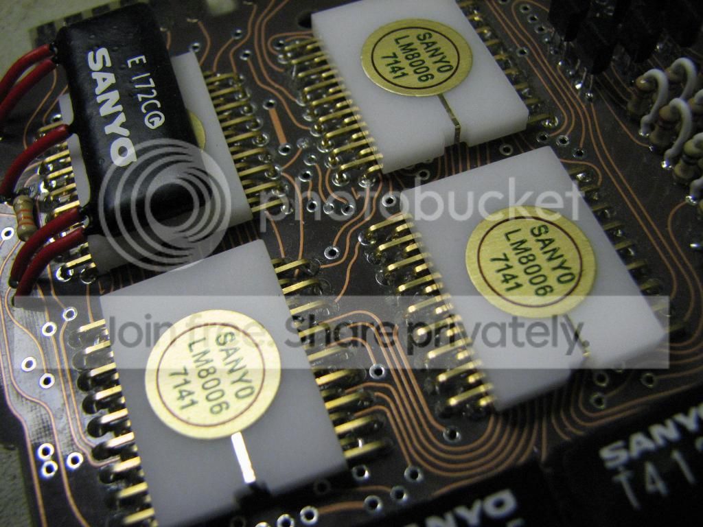
amazing!
That’s some seriously good work. If only you could find the right IC chips, you’d pretty much have a working calculator!
Beautiful work, bishopdonmiguel!
Can you tell us a little bit about your making of the ‘Sanyo E172CG’ part? My kit did seem to come with that part, but I might be mistaken. Thanks!
Thank you Sir! I enjoyed every moment of building this kit… except perhaps removing & reinstalling that nixie!
My kit had a white rectangle with tapered edges included. There were some dimples on one side that aligned with the circuit board so I deduced this was the Sanyo part. This was made of EXTREMELY tough stuff. At first, I tried to heat some spare metal wires and melt them into the part. Fail! Even when the metal was red hot, the stuff didn’t budge. In the end, I resorted to using the smallest Dremel bit I had and supergluing the metal wires in. The stuff was tricky to drill through but maybe the bit was dull.
After the glue dried, I dipped the part in some black Plasticoat I had leftover from my MT500 Antenna Conversion. I let that dry for a full day, then applied the rub on transfer and gave it a coat of clear matte. I used the leftover heat shrink to cover the wires.
Thanks! Now that’s an idea!
Thanks Doug! I am gonna find some of that golf pin stripe and borrow your improvement. Looks great!
Awesome! I noticed the piece in the kit and thought it might be the Sanyo part, and now I know. I’m gonna try drilling holes for the wires with a SHARP bit Thanks for the info!