3D printing a PKE Meter for my son's halloween costume (arduino based with source added)

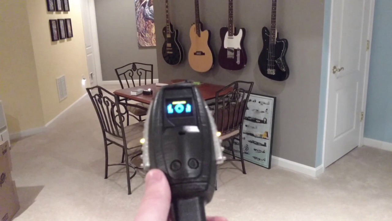
I have to say I wish I would have found this site before I started this journey. My son has decided that he wants to be a ghostbuster for halloween and have a ghostbusters birthday. His birthday is Nov 1 so it works out well. I found a number of plans on Thingiverse for proton packs, traps, and PKE Meters and decided I’d take a crack at one of them. I originally thought the PKE Meter would be the easiest so started with that. I now think I was wrong as it was difficult to get the electronics as small as I needed it. About a month later I’ve completed it and it looks like this:

It’s based off this model on Thingiverse I scaled it up to 110%, removed a few buttons to make it easier to use for my son, and created a new battery holder for the 4 AAA’s that power it. I decided on an Arduino nano as the brains with a cheap LCD for display. Again, not going for screen accurate but something that will keep a 6-7 year old entertained. I did program in the Ghostbusters 2 LED pattern for the wings.

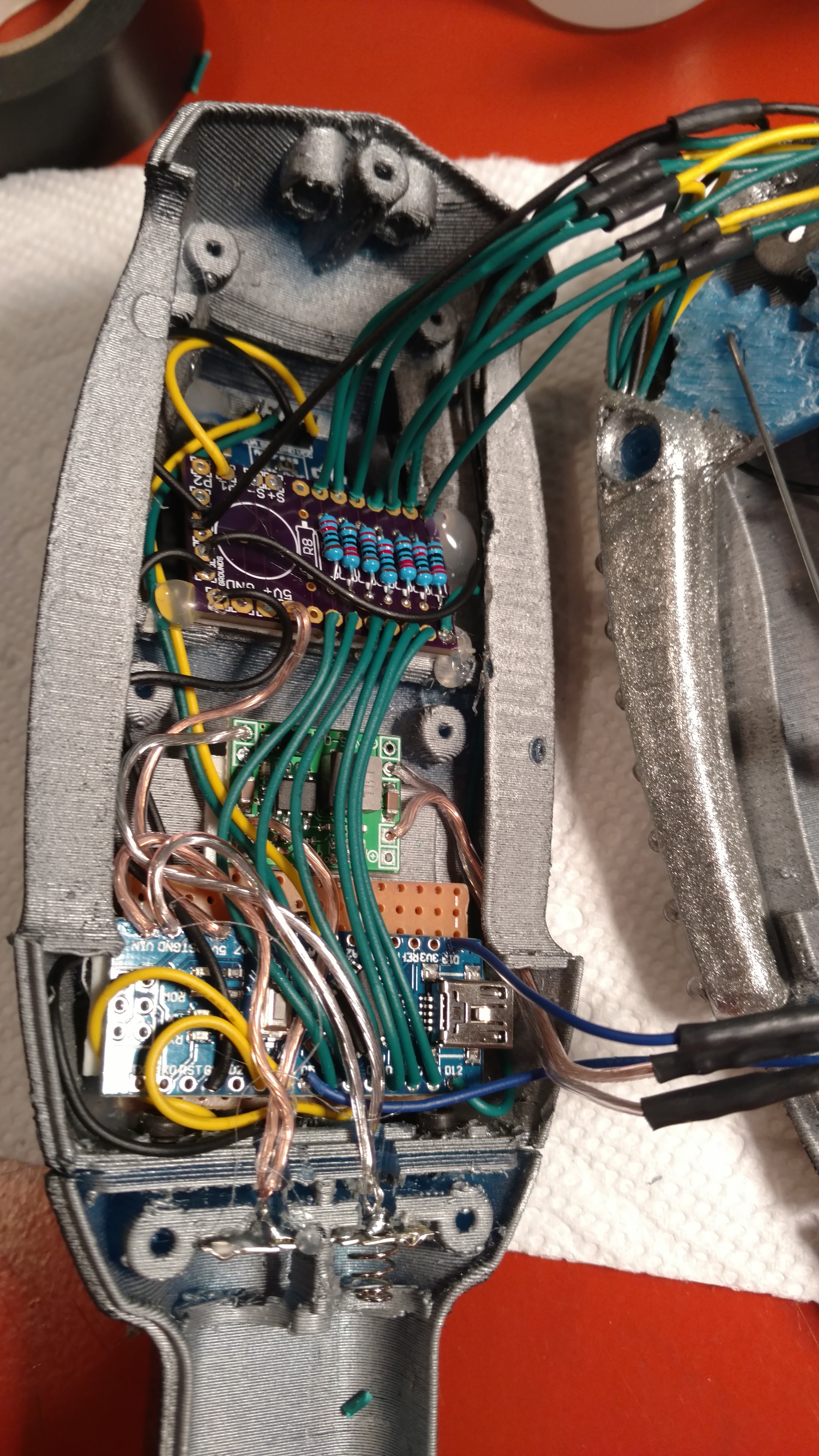
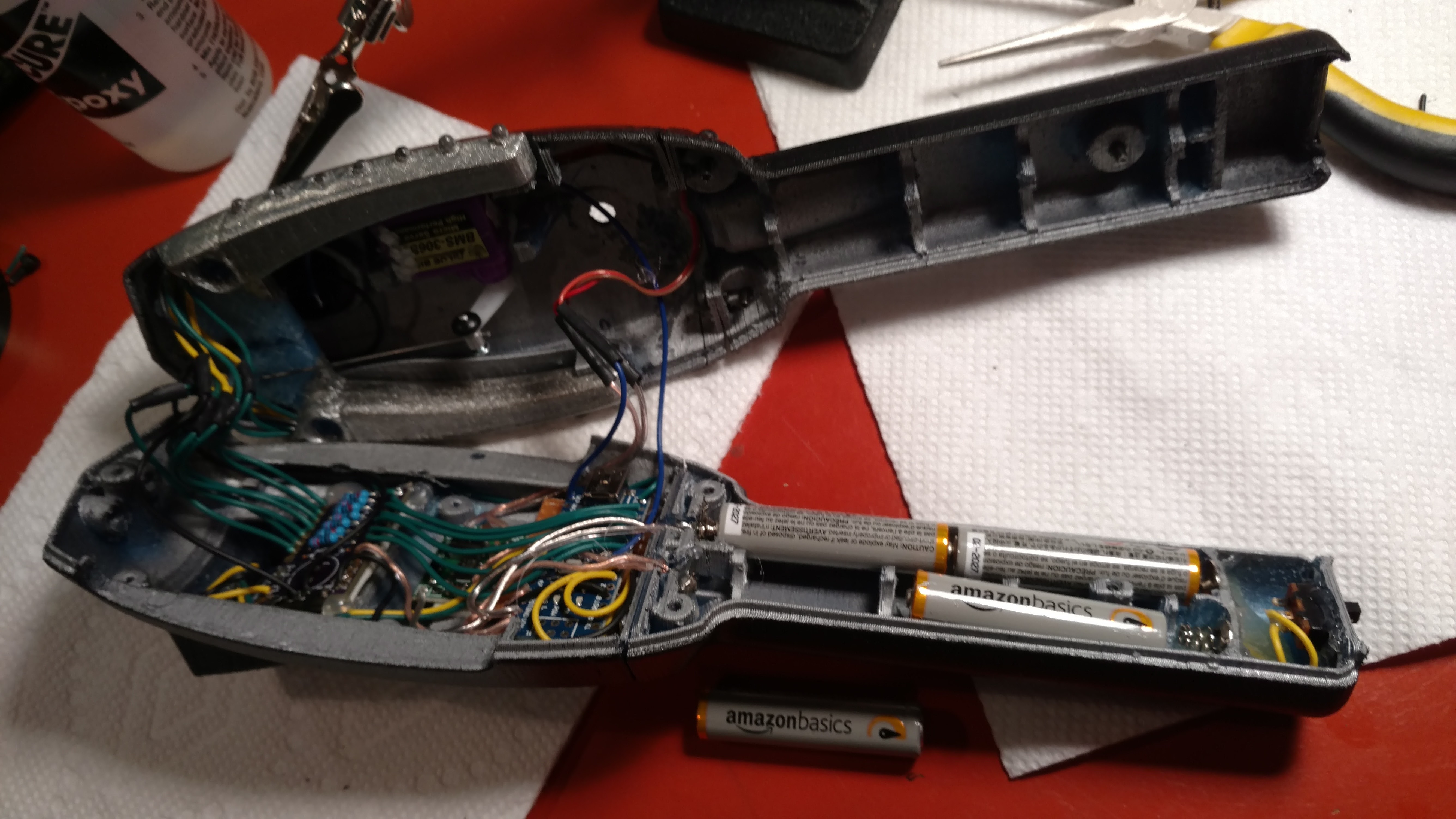
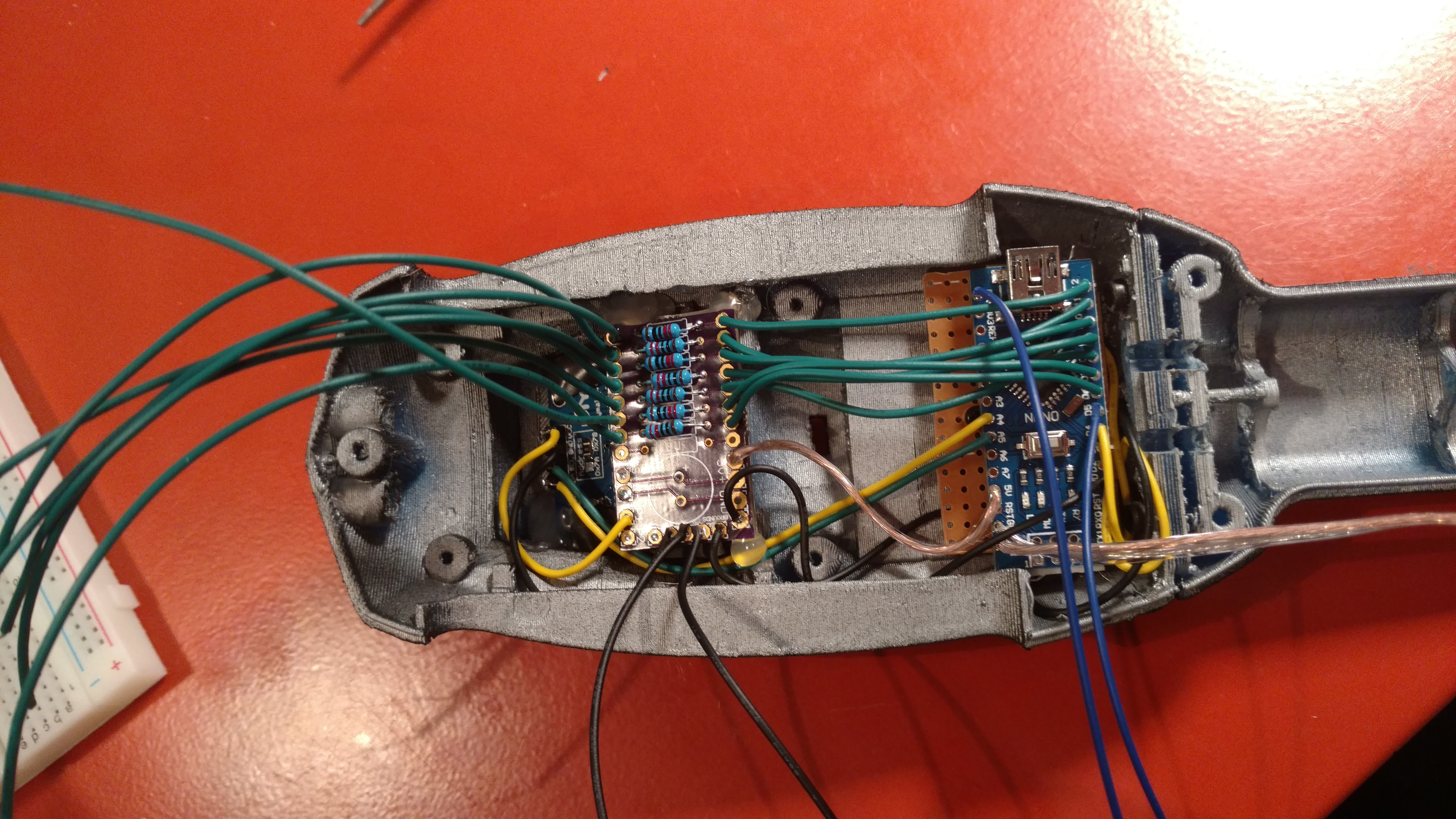
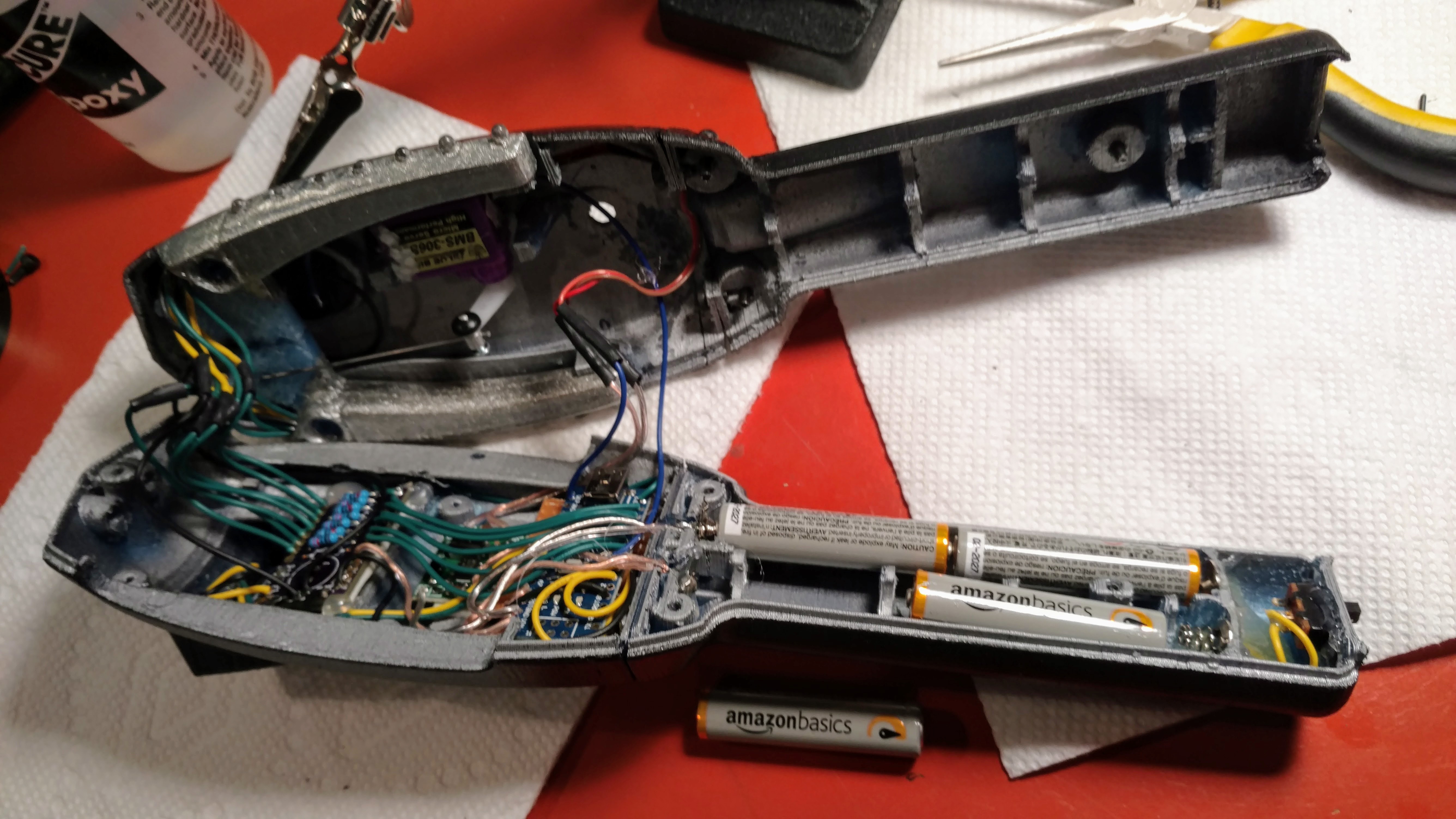
The big trick to all of this was getting the electronics to fit in such a small place. I build my own PCB from OshPark for the LED driver board/5v rail to power everything. This worked out pretty good.

it took me about a month from start to finish to build this. I’m really pleased with how it came out. All told it cost me about $50 for materials and parts to build it.

Now I’m starting in on a proton pack for him. Sure hope I can get it all done by halloween

**Update **

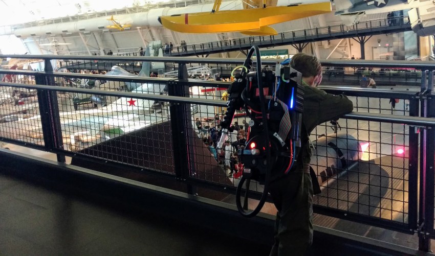
I did finish the proton pack in time for Halloween :slight_smile: He was one awesome ghostbuster this year

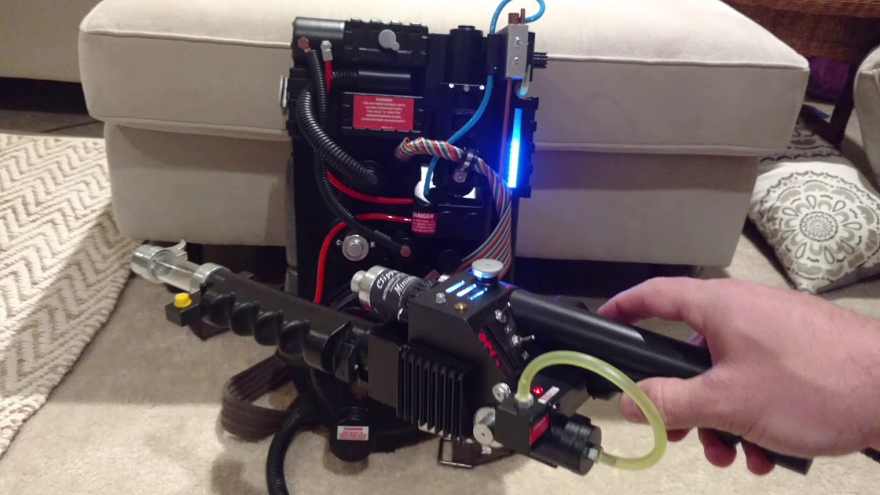
Video of the final proton pack:

Great job! Love the lcd screen.

Thanks :slight_smile: I was originally going to use LED’s like most other builds I have seen but when I saw the little LCD was less than $10 I thought I would give it a try. The one I bought is not in stock anymore but this one is basically the same thing

https://www.amazon.com/LANMU-Serial-128X64-Display-Arduino/dp/B01G6SAWNY?tag=gbfans-discourse-20

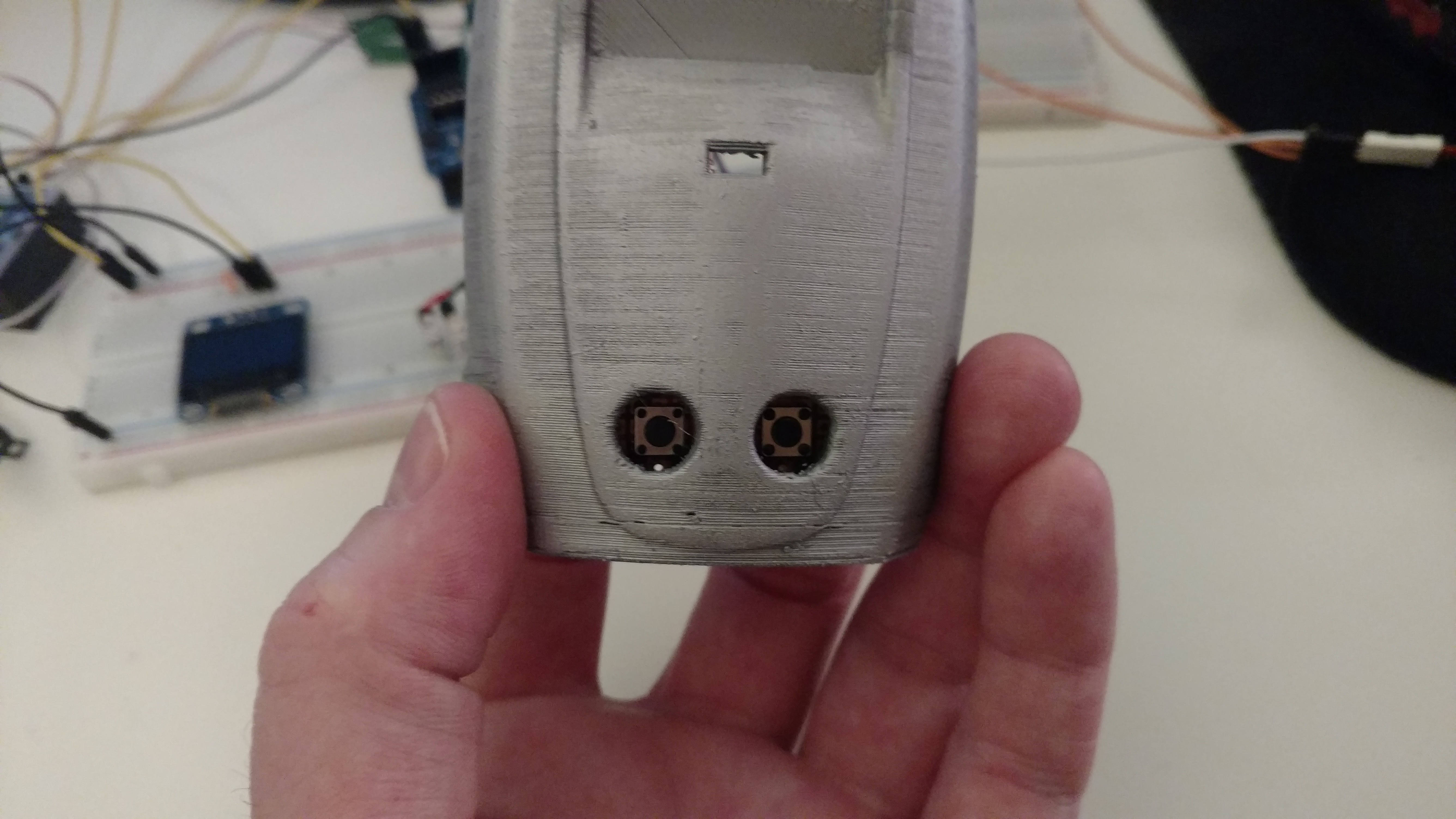
Now that my son has used it a bunch I’m thinking of changing how the buttons work. Instead a press and hold I might make them a toggle.

Links in this post may be affiliate links. Purchases made through them help support this site at no additional cost to you.
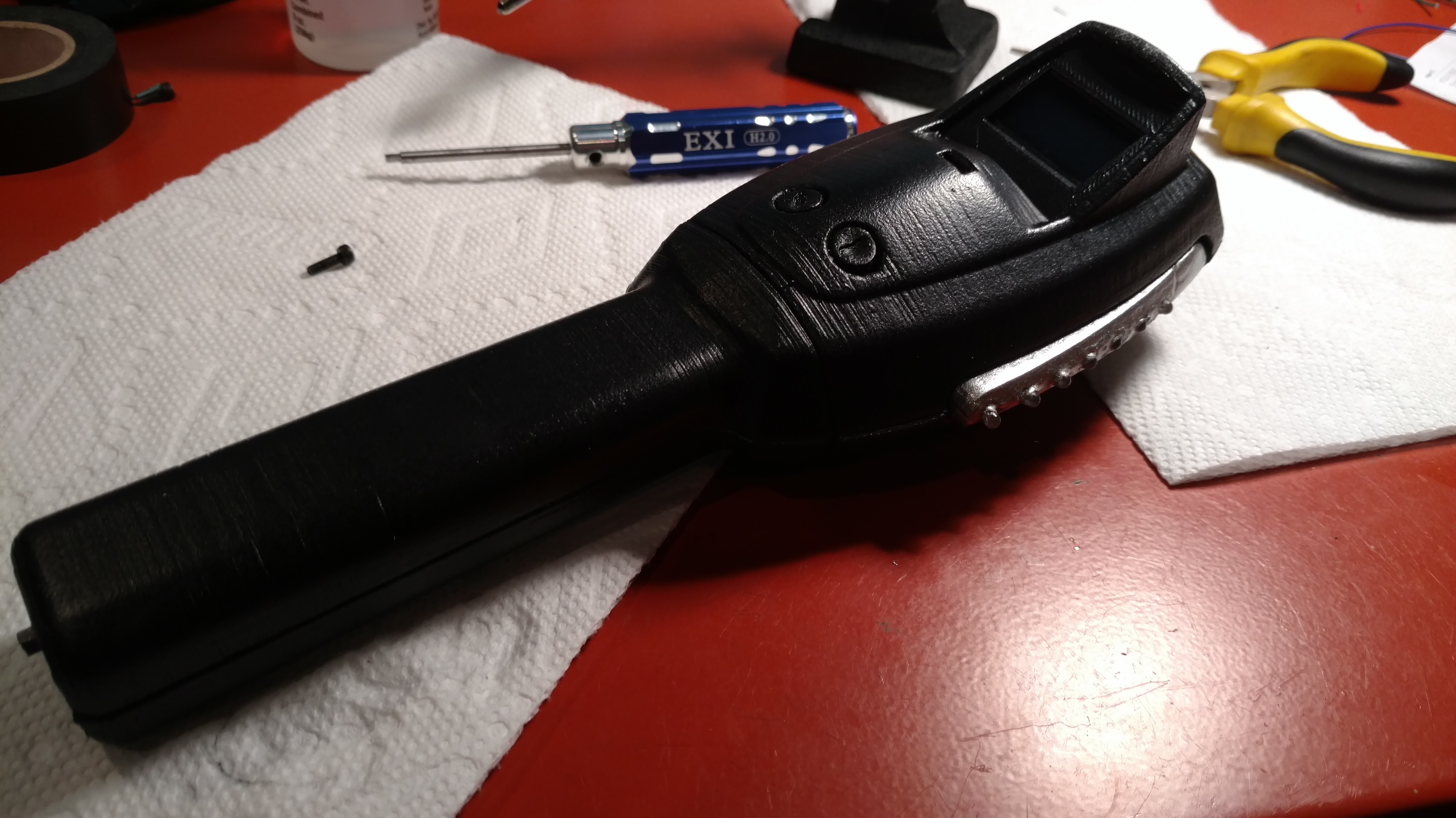
I might as well share the code for all of this. I don’t have any full diagrams of everything but it’s not that complex. I have zipped everything up including my Eagle board/schematic files if you wanted to order from oshpark or modify my boards. I have some extra 5v outputs on the rail and an extra LED spot. It also has an extra separate input with a capacitor. I was originally going to run the servo off the 5v from arduino but decided things would be more stable to run from the buck converter and the boards were already in fab when I decided to do that.

It’s been a fun project. Now I’m starting in on the pack using a pair of arduino nano’s and an Adafruit Audio FX Sound Board

A zip file with the 3D model STL files for printing, eagle files for the pcb, and the arduino code

The original model comes from here http://www.thingiverse.com/thing:700251 and is under the creative commons license

As far as hardware goes it uses:

The wiring is not so hard. From the battery pack 1 power/ground to the arduino vin/gnd pins and 1 power/ground to the buck converter. The converter is then adjusted for a 5v output and that goes to the power/ground of the servo. The full pin out from the arduino looks like this:

<i>
</i>vin/gnd - to power
5v/gnd - to board from oshpark
A4 - SDA on LCD Display
A5 - SLC on LCD Display
D3 - Button 1 +
D4 - Button 2 +
D5 - Buzzer +
D6 - LED 1  (A7 on OshPark board)
D7 - LED 2  (A6 on OshPark board)
D8 - LED 3  (A5 on OshPark board)
D9 - LED 4  (A4 on OshPark board)
D10 - LED 5 (A3 on OshPark board)
D11 - LED 6 (A2 on OshPark board)
D12 - LED 7 (A1 on OshPark board)
D13 - Servo Signal

OshPark Board
P1 - 5v + on LCD Display
G - Gnd on LCD Display
G - Gnd on Buzzer
G - Shared ground on button board
G - Shared ground on LED wings

For the LED's I used 1 output from 1-7 on the board from OshPark to each wing.
Yes I am using one resistor for 2 LED's.
The current in this setup is less than 10ma so they will be fine

And here is the arduino code.

<i>
</i>#include <Servo.h>
#include <Adafruit_GFX.h>
#include <Adafruit_SSD1306.h>

#define OLED_RESET 4
Adafruit_SSD1306 display(OLED_RESET);

Servo SERVO1;

int LEDNum = 0; // current LED that is lit
unsigned long previousMillis;   // will store last time LED was updated

const int LED1 = 12;
const int LED2 = 11;
const int LED3 = 10;
const int LED4 = 9;
const int LED5 = 8;
const int LED6 = 7;
const int LED7 = 6;
const int BUZZER = 5;
const int BUTTON1 = 3;
const int BUTTON2 = 4;

void setup() {
  pinMode(LED1, OUTPUT);
  pinMode(LED2, OUTPUT);
  pinMode(LED3, OUTPUT);
  pinMode(LED4, OUTPUT);
  pinMode(LED5, OUTPUT);
  pinMode(LED6, OUTPUT);
  pinMode(LED7, OUTPUT);
  pinMode(BUZZER, OUTPUT);
  pinMode(BUTTON1, INPUT);
  pinMode(BUTTON2, INPUT);

  digitalWrite(BUTTON1, HIGH);
  digitalWrite(BUTTON2, HIGH);

  display.begin(SSD1306_SWITCHCAPVCC, 0x3C);
  display.display();
  delay(1000);

  // Clear the buffer.
  display.clearDisplay();

  SERVO1.attach(13);
  SERVO1.write(90);
}

void loop() {
  int convertedVal = 0;
  if (digitalRead(BUTTON1) == false) {
     convertedVal = 40;
  }else if(digitalRead(BUTTON2) == false) {
    convertedVal = 90;
  }

  // do the led stuff
  LEDLoop(convertedVal);

  // do the servo stuff
  ServoLoop(convertedVal);

  // delay in between reads for stability
  delay(1);
}

int prevB = 0;
void drawDisplay(int level, int bar) {
  display.setTextSize(1);
  display.setTextColor(WHITE);
  display.setCursor(29, 5);
  display.print("GHOSTBUSTERS");

  int b1 = random(prevB, bar);
  int b2 = random(prevB, bar);
  int b3 = random(prevB, bar);
  int b4 = random(prevB, bar);
  int b5 = random(prevB/2, bar/2);
  int b6 = random(prevB/2, bar/2);
  prevB = bar;

  display.fillRect(2, display.height() - (5 + b1), 5, b1, WHITE);
  display.fillRect(10, display.height() - (5 + b2), 5, b2, WHITE);
  display.fillRect(18, display.height() - (5 + b5), 5, b5, WHITE);
  display.fillRect(display.width() - 23, display.height() - (5 + b6), 5, b6, WHITE);
  display.fillRect(display.width() - 15, display.height() - (5 + b4), 5, b4, WHITE);
  display.fillRect(display.width() - 7, display.height() - (5 + b3), 5, b3, WHITE);

  display.drawCircle(display.width() / 2, display.height() / 2 + 7, level, WHITE);

  display.display();
}

void clearLoop() {
  display.clearDisplay();
  prevB = 0;
}

void LEDLoop(int convertedVal) {
  int ledSpeed = map(convertedVal, 0, 100, 500, 20);

  // check to see if it's time to change the state of the LED
  unsigned long currentMillis = millis();

  if ((currentMillis - previousMillis >= ledSpeed))
  {
    previousMillis = millis();

    if ( LEDNum == 0 ) {
      TriggerBuzzer();
      clearLoop();
      digitalWrite(LED3, true);
      LEDNum = 1;
      drawDisplay(21, 5);
    } else if ( LEDNum == 1 ) {
      TriggerBuzzer();
      digitalWrite(LED3, false);
      digitalWrite(LED1, true);
      LEDNum = 2;
      drawDisplay(18, 20);
    } else if ( LEDNum == 2 ) {
      TriggerBuzzer();
      digitalWrite(LED1, false);
      digitalWrite(LED6, true);
      LEDNum = 3;
      drawDisplay(15, 30);
    } else if ( LEDNum == 3 ) {
      TriggerBuzzer();
      digitalWrite(LED6, false);
      digitalWrite(LED4, true);
      LEDNum = 4;
      drawDisplay(12, 45);
    } else if ( LEDNum == 4 ) {
      TriggerBuzzer();
      digitalWrite(LED4, false);
      digitalWrite(LED7, true);
      LEDNum = 5;
      drawDisplay(9, 50);
    } else if ( LEDNum == 5 ) {
      TriggerBuzzer();
      digitalWrite(LED7, false);
      digitalWrite(LED5, true);
      LEDNum = 6;
      drawDisplay(6, 55);
    } else if ( LEDNum == 6 ) {
      TriggerBuzzer();
      digitalWrite(LED5, false);
      digitalWrite(LED2, true);
      LEDNum = 7;
      drawDisplay(3, 65);
    }else if ( LEDNum == 7 ) {
      TriggerBuzzer();
      clearLoop();
      digitalWrite(LED2, false);
      digitalWrite(LED3, true);
      LEDNum = 1;
      drawDisplay(21, 5);
    }
  }
}

void TriggerBuzzer() {
  tone(BUZZER, 2000); // Send 2KHz sound signal...
  delay(20);        // ...for 20 msec
  noTone(BUZZER);
}

void ServoLoop(int convertedVal) {
  int servoVal = map(convertedVal, 0, 100, 110, 40);
  SERVO1.write(servoVal);
}

Links in this post may be affiliate links. Purchases made through them help support this site at no additional cost to you.
Wow! Thank you so much! I have an Iona polisher I have been putting off gutting because the electronics had me worried but i can totally use all of this as a starting point now to get mine off the ground!

Good luck. Arduino is a lot of fun to play with.

I changed the code to toggle each state instead of requiring the button be held down. I found this is easier for my son to use. I now have everything in github here:

The current code:

<i>
</i>#include <Servo.h>
#include <Adafruit_GFX.h>
#include <Adafruit_SSD1306.h>

#define OLED_RESET 4
Adafruit_SSD1306 display(OLED_RESET);

Servo SERVO1;

int LEDNum = 0; // current LED that is lit
unsigned long previousMillis;   // will store last time LED was updated

const int LED1 = 12;
const int LED2 = 11;
const int LED3 = 10;
const int LED4 = 9;
const int LED5 = 8;
const int LED6 = 7;
const int LED7 = 6;
const int BUZZER = 5;
const int BUTTON1 = 3;
const int BUTTON2 = 4;

// know thy button state
bool medium_state = false;
bool high_state = false;
bool button1_down = false;
bool button2_down = false;

void setup() {
  pinMode(LED1, OUTPUT);
  pinMode(LED2, OUTPUT);
  pinMode(LED3, OUTPUT);
  pinMode(LED4, OUTPUT);
  pinMode(LED5, OUTPUT);
  pinMode(LED6, OUTPUT);
  pinMode(LED7, OUTPUT);
  pinMode(BUZZER, OUTPUT);
  pinMode(BUTTON1, INPUT);
  pinMode(BUTTON2, INPUT);

  digitalWrite(BUTTON1, HIGH);
  digitalWrite(BUTTON2, HIGH);

  display.begin(SSD1306_SWITCHCAPVCC, 0x3C);
  display.display();
  delay(500);

  // Clear the buffer.
  display.clearDisplay();

  SERVO1.attach(13);
  SERVO1.write(90);
}

// current display val
int currentVal = 0;
void loop() {
  int button1 = digitalRead(BUTTON1);
  int button2 = digitalRead(BUTTON2);

  if( button1 == LOW && button1_down == false ){
		  button1_down = true;

      if ( medium_state == true) {
        medium_state = false;
        high_state = false;
        currentVal = 0;
      }else {
  			medium_state = true;
  			high_state = false;
  			currentVal = 40;
		  }
  } else {
	  if (button1 == HIGH && button1_down == true ){
		  button1_down = false;
	  }
  }

  if( button2 == LOW && button2_down == false ){
    button2_down = true;

    if(high_state == true) {
      medium_state = false;
      high_state = false;
      currentVal = 0;
    }else {
      medium_state = false;
      high_state = true;
      currentVal = 90;
    }
  }else{
    if (button2 == HIGH && button2_down == true ){
      button2_down = false;
    }
  }
 .z
  // do the led stuff
  LEDLoop(currentVal);

  // do the servo stuff
  ServoLoop(currentVal);

  // delay in between reads for stability
  delay(1);
}

int prevB = 0;
void drawDisplay(int level, int bar) {
  display.setTextSize(1);
  display.setTextColor(WHITE);
  display.setCursor(29, 5);
  display.print("GHOSTBUSTERS");

  int b1 = random(prevB, bar);
  int b2 = random(prevB, bar);
  int b3 = random(prevB, bar);
  int b4 = random(prevB, bar);
  int b5 = random(prevB/2, bar/2);
  int b6 = random(prevB/2, bar/2);
  prevB = bar;

  display.fillRect(2, display.height() - (5 + b1), 5, b1, WHITE);
  display.fillRect(10, display.height() - (5 + b2), 5, b2, WHITE);
  display.fillRect(18, display.height() - (5 + b5), 5, b5, WHITE);
  display.fillRect(display.width() - 23, display.height() - (5 + b6), 5, b6, WHITE);
  display.fillRect(display.width() - 15, display.height() - (5 + b4), 5, b4, WHITE);
  display.fillRect(display.width() - 7, display.height() - (5 + b3), 5, b3, WHITE);

  display.drawCircle(display.width() / 2, display.height() / 2 + 7, level, WHITE);

  display.display();
}

void clearLoop() {
  display.clearDisplay();
  prevB = 0;
}

void LEDLoop(int convertedVal) {
  int ledSpeed = map(convertedVal, 0, 100, 500, 20);

  // check to see if it's time to change the state of the LED
  unsigned long currentMillis = millis();

  if ((currentMillis - previousMillis >= ledSpeed))
  {
    previousMillis = millis();

    if ( LEDNum == 0 ) {
      TriggerBuzzer();
      clearLoop();
      digitalWrite(LED3, true);
      LEDNum = 1;
      drawDisplay(21, 5);
    } else if ( LEDNum == 1 ) {
      TriggerBuzzer();
      digitalWrite(LED3, false);
      digitalWrite(LED1, true);
      LEDNum = 2;
      drawDisplay(18, 20);
    } else if ( LEDNum == 2 ) {
      TriggerBuzzer();
      digitalWrite(LED1, false);
      digitalWrite(LED6, true);
      LEDNum = 3;
      drawDisplay(15, 30);
    } else if ( LEDNum == 3 ) {
      TriggerBuzzer();
      digitalWrite(LED6, false);
      digitalWrite(LED4, true);
      LEDNum = 4;
      drawDisplay(12, 45);
    } else if ( LEDNum == 4 ) {
      TriggerBuzzer();
      digitalWrite(LED4, false);
      digitalWrite(LED7, true);
      LEDNum = 5;
      drawDisplay(9, 50);
    } else if ( LEDNum == 5 ) {
      TriggerBuzzer();
      digitalWrite(LED7, false);
      digitalWrite(LED5, true);
      LEDNum = 6;
      drawDisplay(6, 55);
    } else if ( LEDNum == 6 ) {
      TriggerBuzzer();
      digitalWrite(LED5, false);
      digitalWrite(LED2, true);
      LEDNum = 7;
      drawDisplay(3, 65);
    }else if ( LEDNum == 7 ) {
      TriggerBuzzer();
      clearLoop();
      digitalWrite(LED2, false);
      digitalWrite(LED3, true);
      LEDNum = 1;
      drawDisplay(21, 5);
    }
  }
}

void TriggerBuzzer() {
  tone(BUZZER, 2000); // Send 2KHz sound signal...
  delay(20);        // ...for 20 msec
  noTone(BUZZER);
}

void ServoLoop(int convertedVal) {
  int servoVal = map(convertedVal, 0, 100, 110, 40);
  SERVO1.write(servoVal);
}

Nicely done and thanks for sharing the code.

I updated the thing on thingiverse with a belt holder for it if anyone is interested

Two questions:

  1. Would you share what screws are needed for assembly?

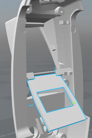
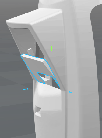
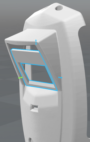
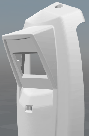
  2. How does the plate for display fit into the main body? It seems like it should go in front of the pegs but I can’t seem to figure out how to slide it in.

I used some m2.5 hex head screws but pretty much any m2.5 screw should work. I don’t remember the exact length. I think the 10mm ones. I bought this a while back for my other hobbies but used some for the pke meter

Haobase 200Pcs DIN912 M2.5 Hex socket head cap screw kit set grad12.9 m2.5 x 4/5/6/8/10/12/14/16/18/20 Amazon.com

The plate slides in from behind. It’s kinda hard to describe so I’ll see if I have a test print laying around to show with pictures. It fits snug but should slide in and lock in.

Links in this post may be affiliate links. Purchases made through them help support this site at no additional cost to you.

I no longer have the test pieces I printed. I think my wife must have cleaned it up. I’ve done the best that I can with the 3d software to show how I do it. The face piece is bent a bit to get it in the area.

start by moving it back and forth as you move it into the display area

With it still not lined up continue to move it up until it you can press it back against the mounts

At this point it should be pretty well lined up and will seat well

Just finish pushing it into place

I did not have to glue mine in. Once in place it won’t move.

Oh I forgot to mention that I put together a fritzing diagram for this setup if you wanted to try breadboarding it.

Awesome! Thank you for all the work on this project.

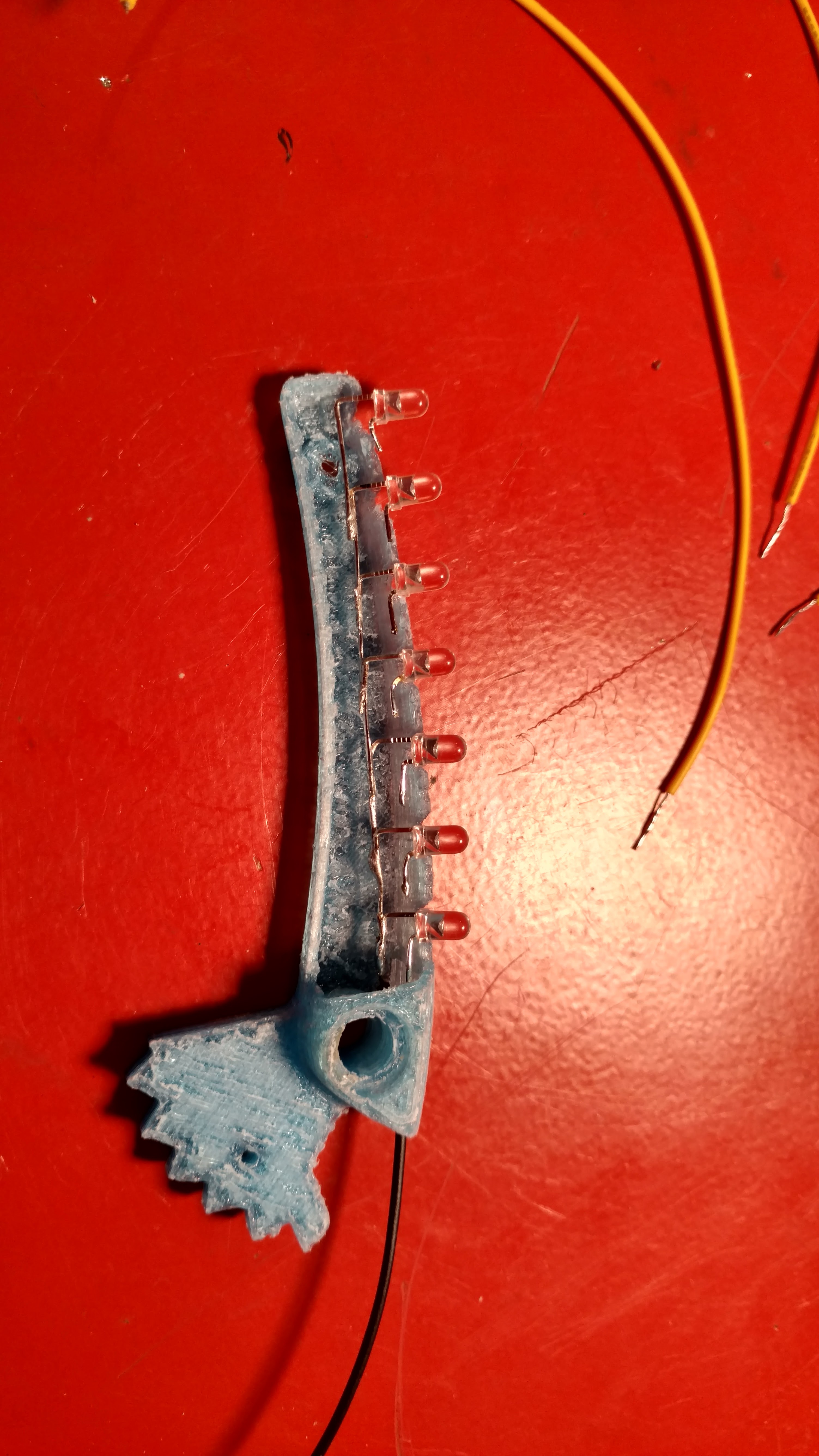
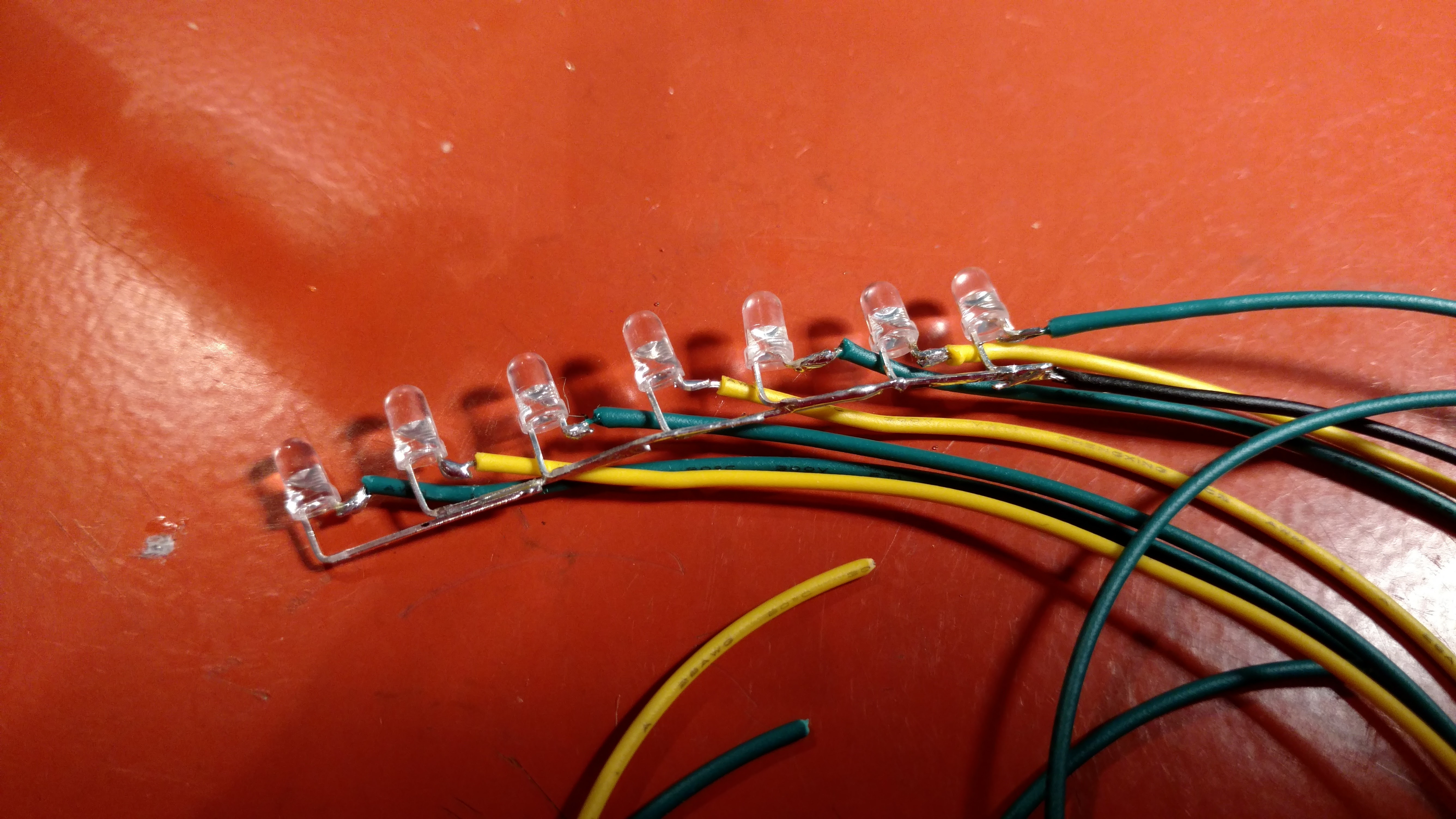
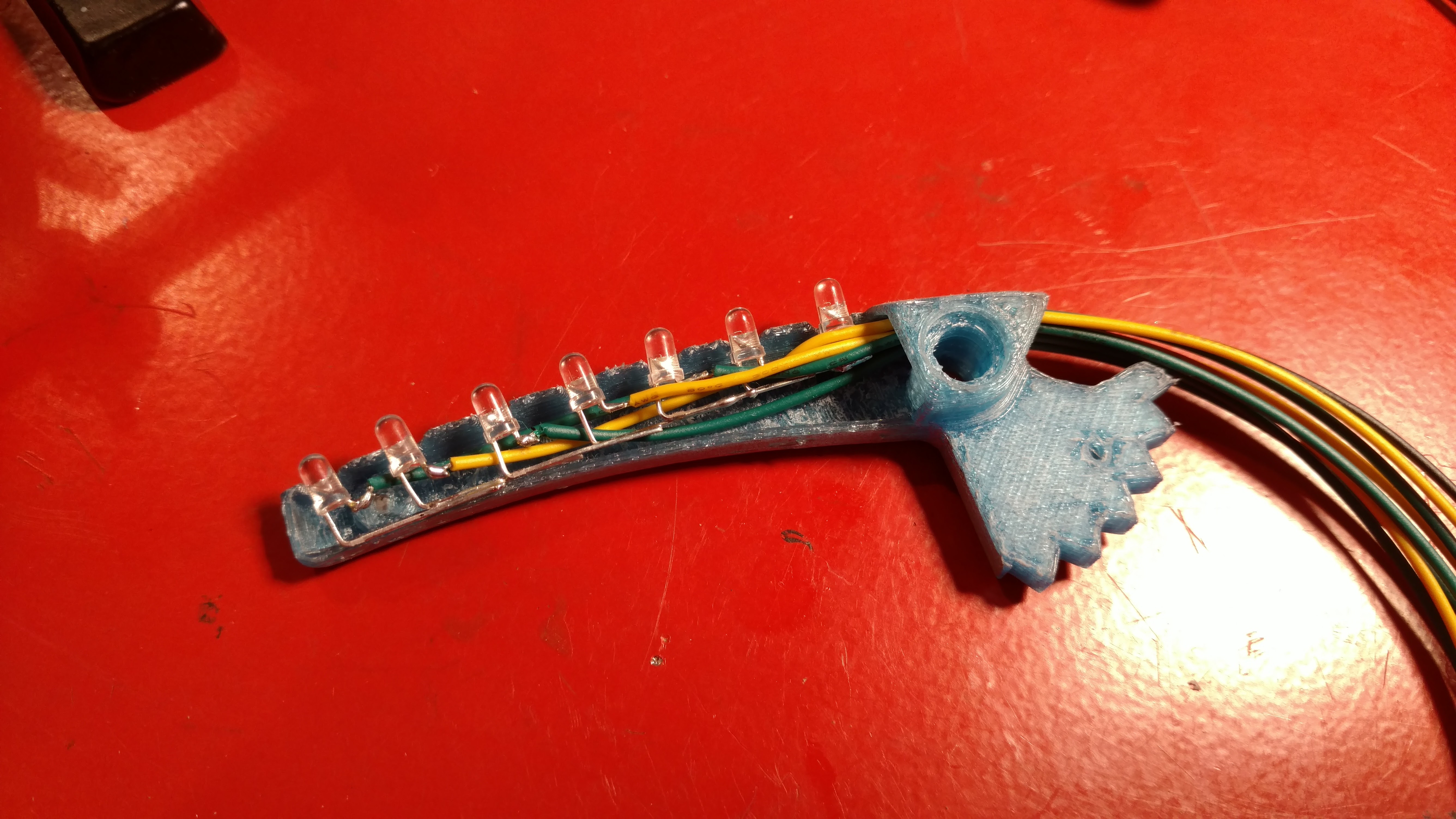
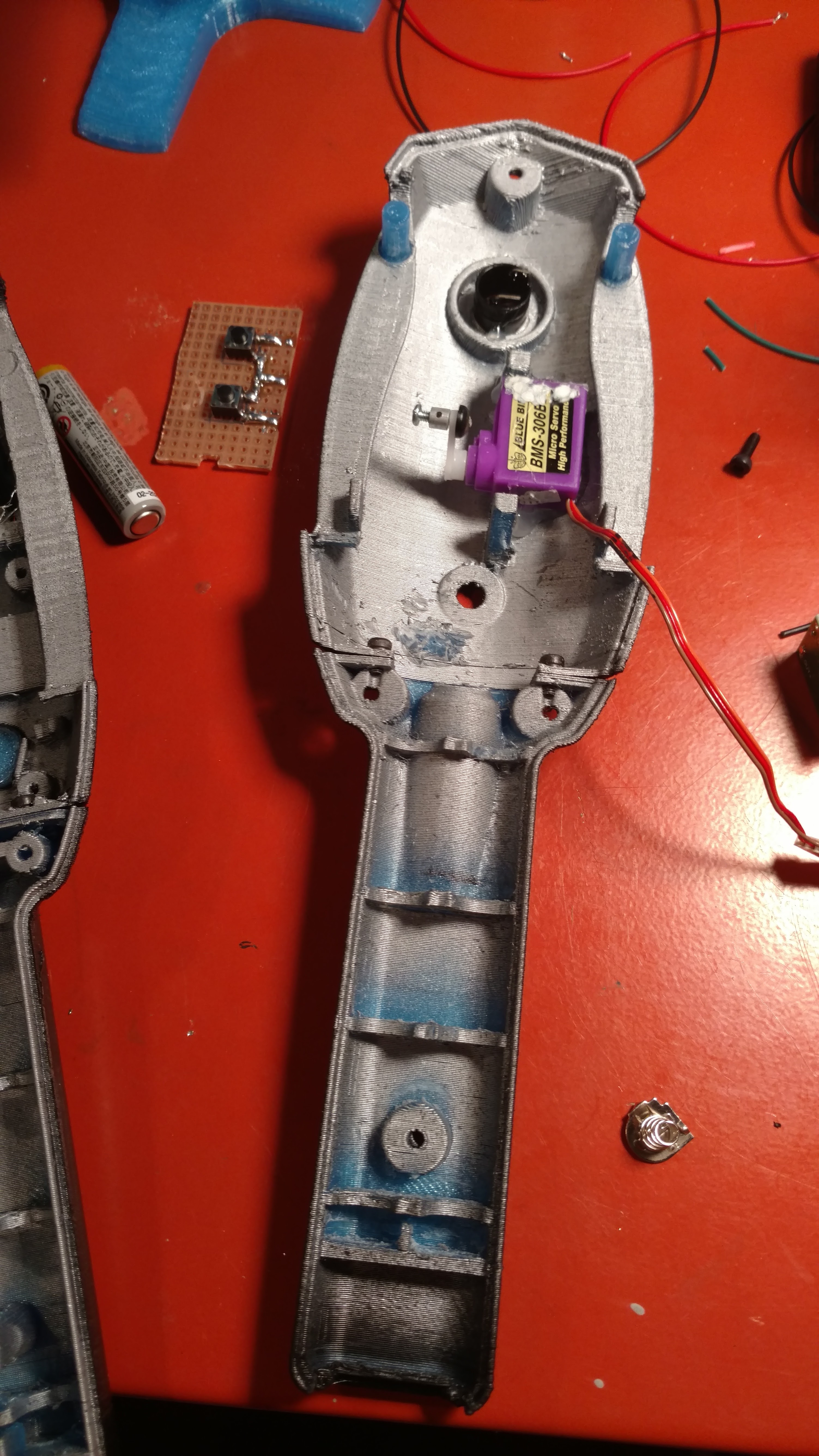
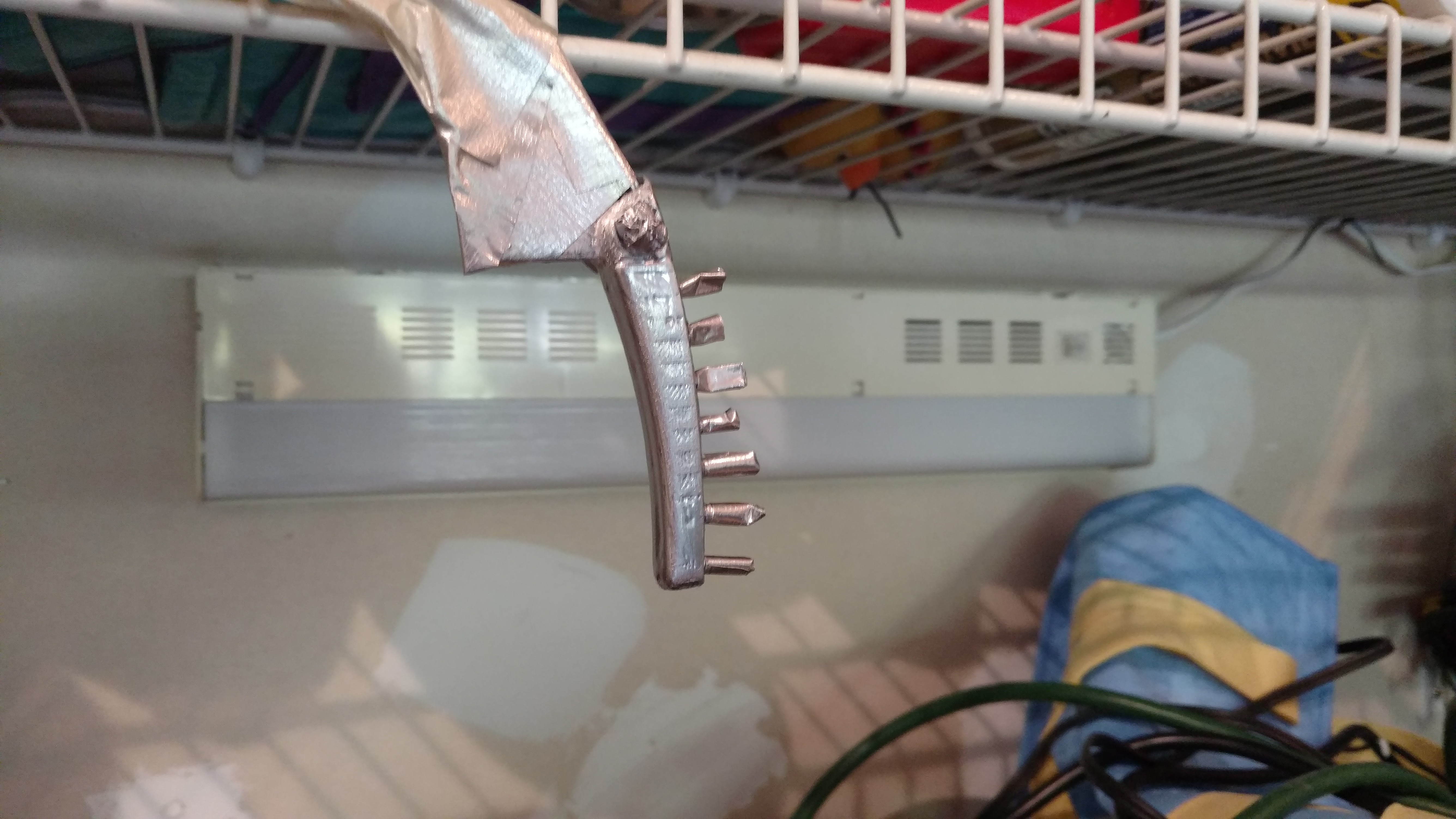
I found a few more pics from the build I thought I would add here as well. They show the installation of the leds in the wings and stuff

Then I pulled it out and soldered the leads on. Here I used the wrong wire so this part would be easier with the wire I recommend

Then I first installed the screen with low temp hot glue

Then the servo and buzzer with the low temp hot glue

I don’t have a picture of it but the button board was mounted and low temp hot glued in. then the arduino was placed on top of it with double sided tape. The custom board was low temp hot glued on top of the screen and the connections were soldered up

I sprayed the wings with the metallic paint (not happy with the chrome I used so resprayed with a more matte finish. Honestly I should have just gone with a dull gray paint I think and not try to chrome it.

The wings were then installed and the wires soldered up. A small servo wire from one of my old rc airplanes was used to connect the servo to the wings. I also installed the wire switch and metal brackets I pulled out of one of my sons toys. And all finished up and ready to be screwed together

Hey count, I am loving this one meter! I have many questions but the biggest one for me is, do you need that eagle board the one you had made by oshpark? From what I gathered the led wires run though it which I could do without the board and it looks also looks like the 5 volt goes from the nano to the board then out to the screen. So the only big thing I see is it allows for several connected grounds is that correct?

No you don’t have to use the board. I used it to clean up the wiring but it can be done without it.

Thanks for sharing this project! I think I’m going to give this one a try.

I have downloaded all the files and while previewing the parts, I’m getting a not manifold error on the front top and the button?

Also, looking at the inside of the front top, I noticed there are a couple features in the part at the lower end that I don’t see in your pictures. Looks like a couple of screw bosses (sticking out of the wall that would butt up against the handle)? What are they for?

Thanks again!

Yeah, there is an issue with both parts. I was able to fix the button one and replace the one on thingiverse. The front top though is not fixable. Cura has no problem slicing it even with the error and netfabb is not able to fix it. I didn’t create the original part. I just modified the stl’s to do what I wanted so I had to work with that. I know there are quite a few people who have printed it with various slicers so you shouldn’t have a problem.

Those two things were remnants from the original part. I used my dremel to remove them

Gotcha! Thank you!