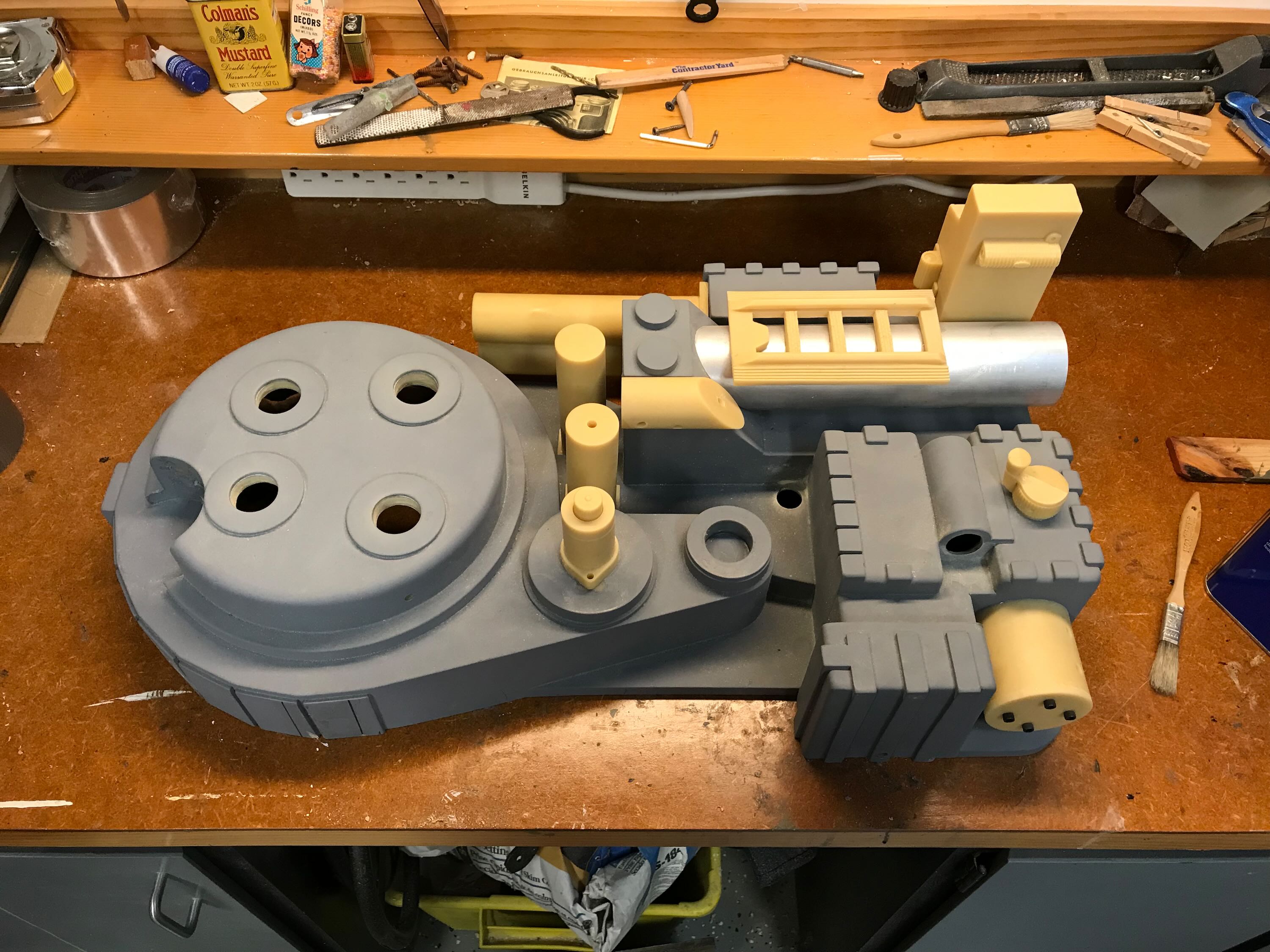
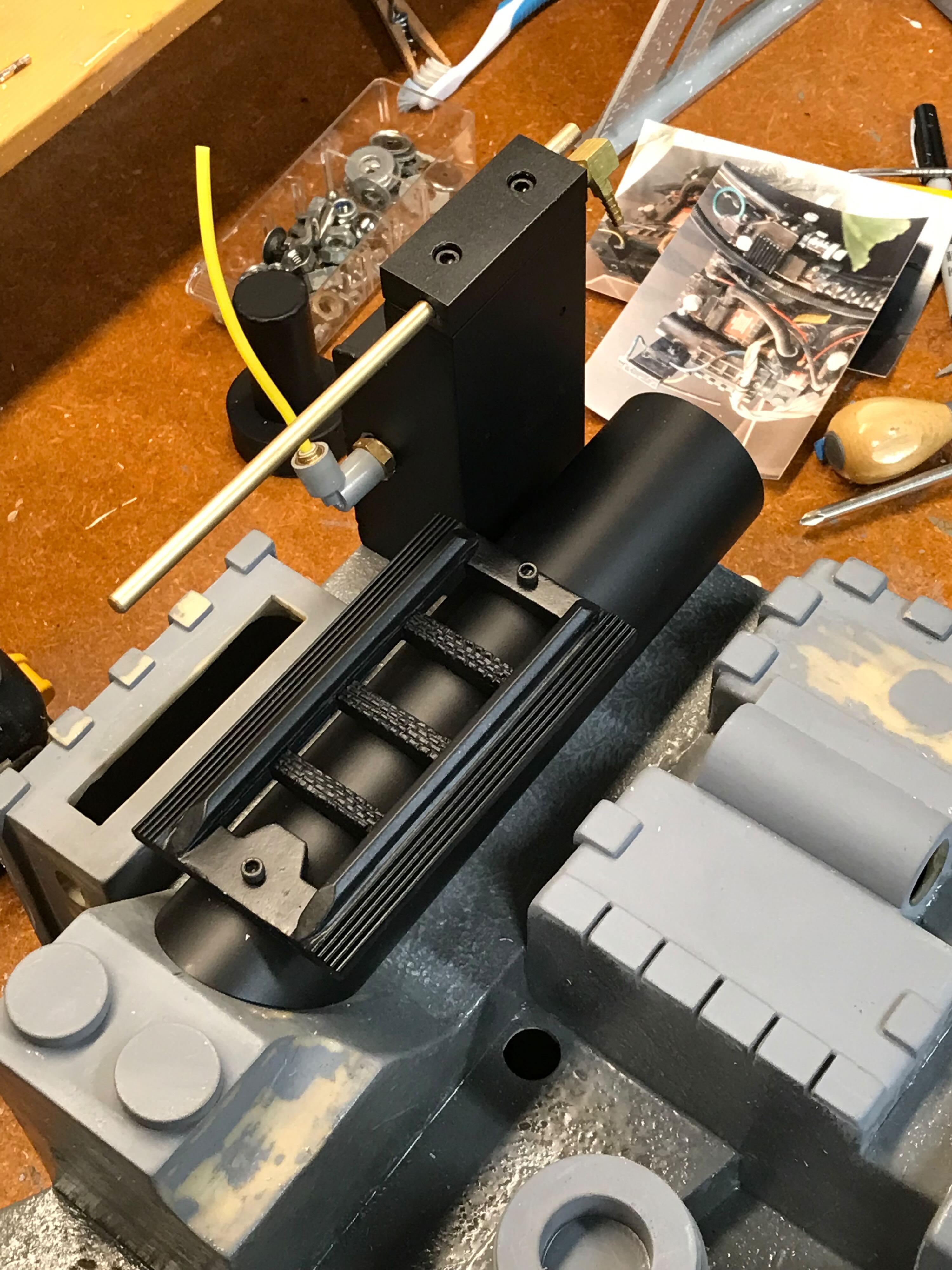
Here’s a thread in which I’ll document the build of a Benofkent Props Proton Pack I’ve decided to build for an acquaintance, Wes Cronin. We’re both members of the Portland Ghostbusters. I scratch-built my Proton Pack in 1984, as documented here Proton Packs-1984 – Shawn Marshall Makes.
Wes bought this kit in 2015 but got stuck. Initially I was just going to help get the Heavy Props electronics sorted out, but as Wes gave me the whole kit back in 2019 I thought it would be a fun distraction from reality to just build the whole thing, pro bono. I hope to get it done in time for a screening of Ghostbusters that the Portland Art Museum film program (PAM CUT) will be holding on July 29. My other goal is to put as little money into completing the prop as possible, so I’ll be using a lot of whatever I have kicking around.
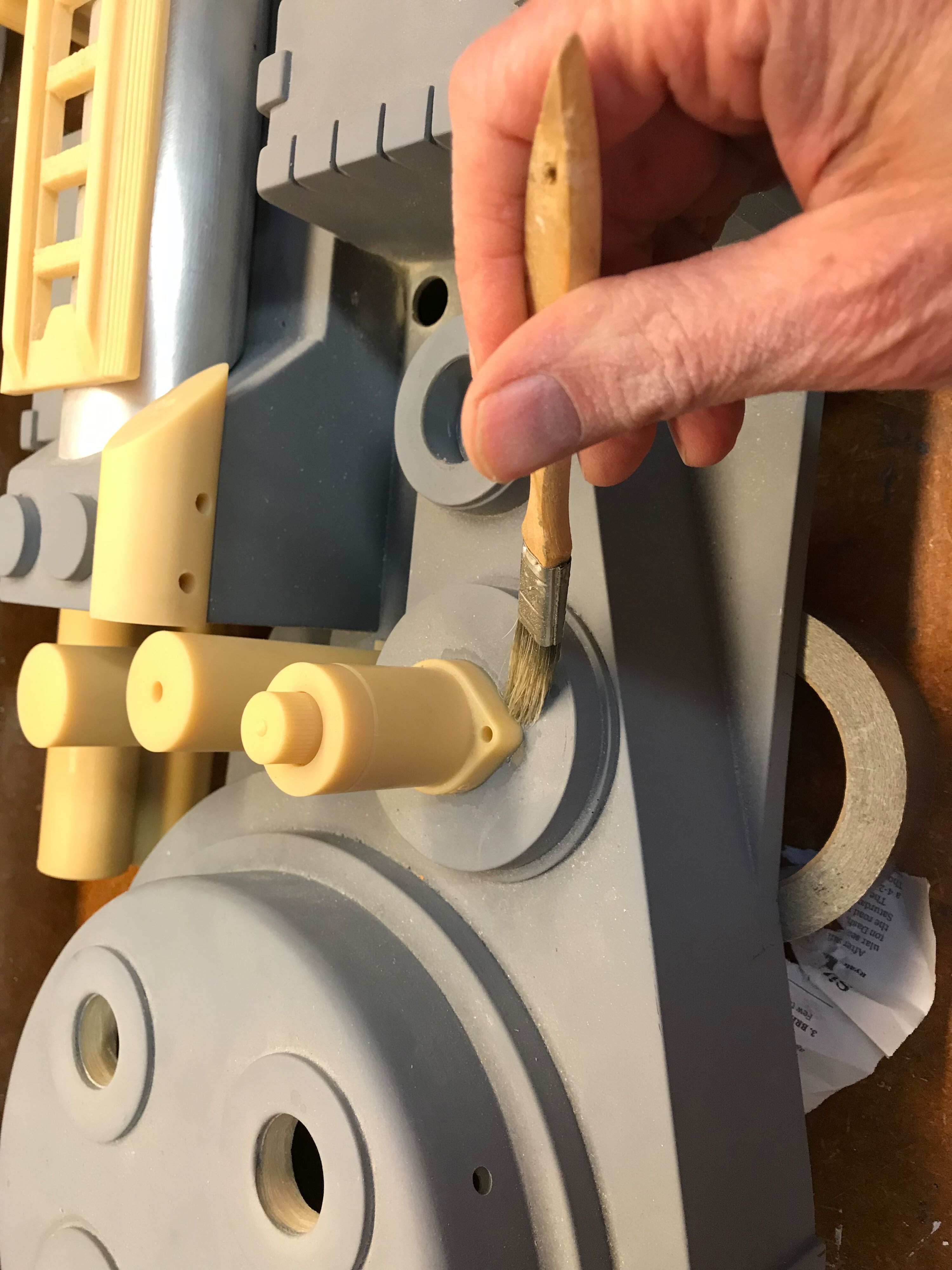
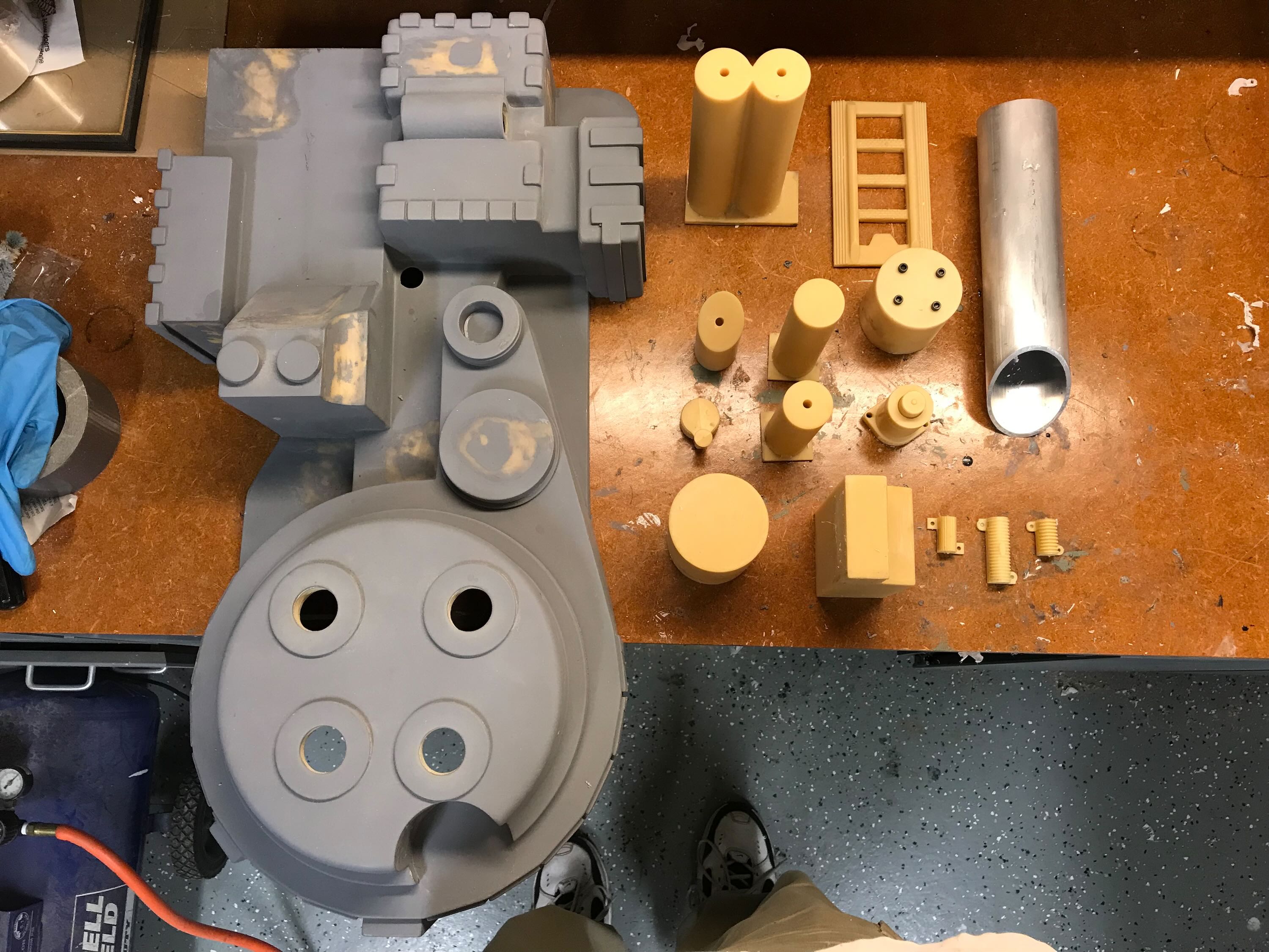
6/14/22 My first task was disassembling the parts Wes had already glued onto the main shell with E6000. It took 2-3 hours using acetone and careful prying with a sharp putty knife to remove all of those parts.
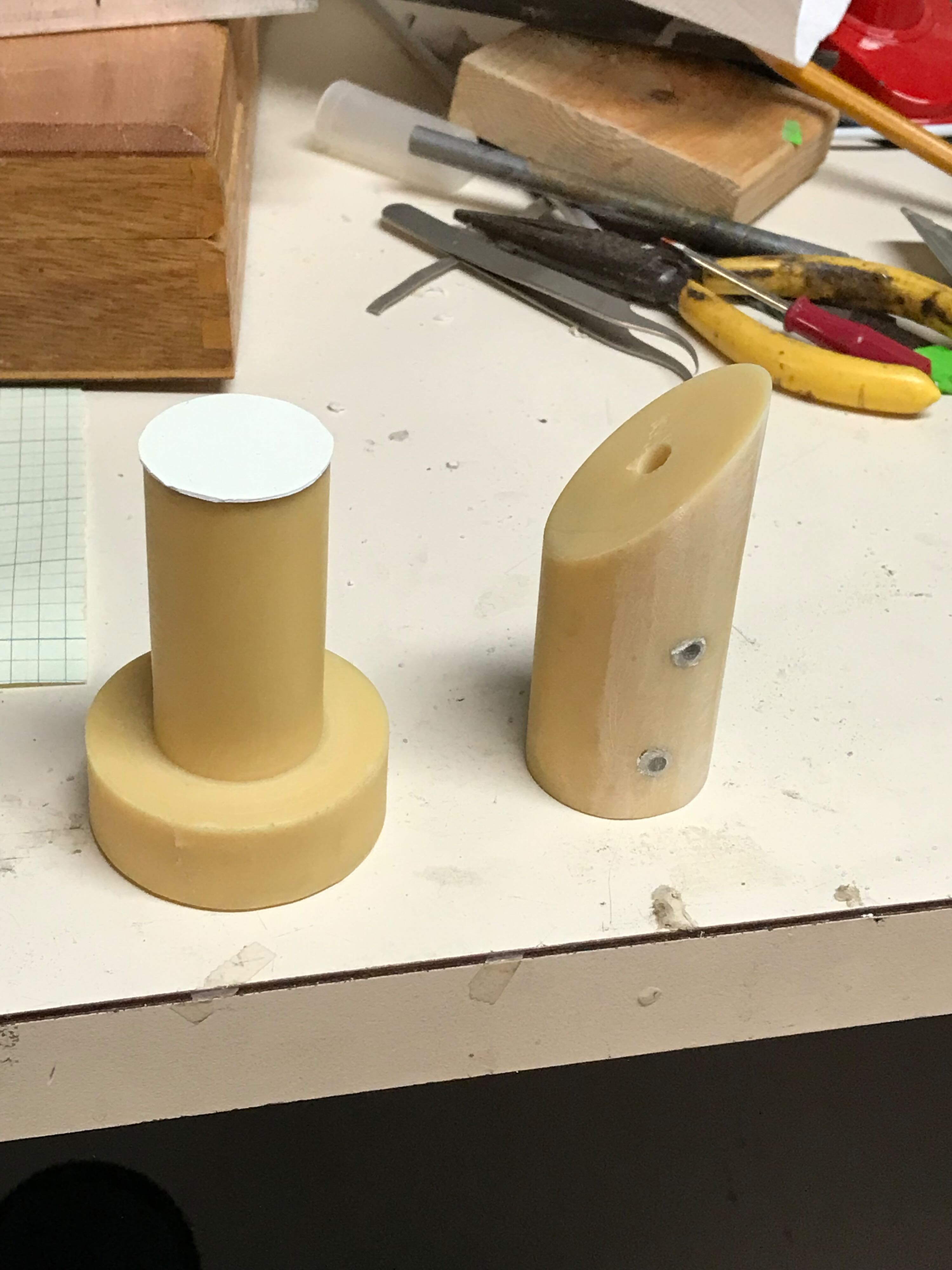
6/15/22 Wes made a few mistakes drilling and modifying some of the resin parts. It wasn’t a huge task to repair those. If you haven’t had much experience building models or props it can be a daunting task to build a Proton Pack kit like this. I give Wes a lot of credit for investing in a Benofkent kit that will yield a full-scale and accurate replica of the movie prop. This should be a LOT more accurate than my build from 38 years ago.
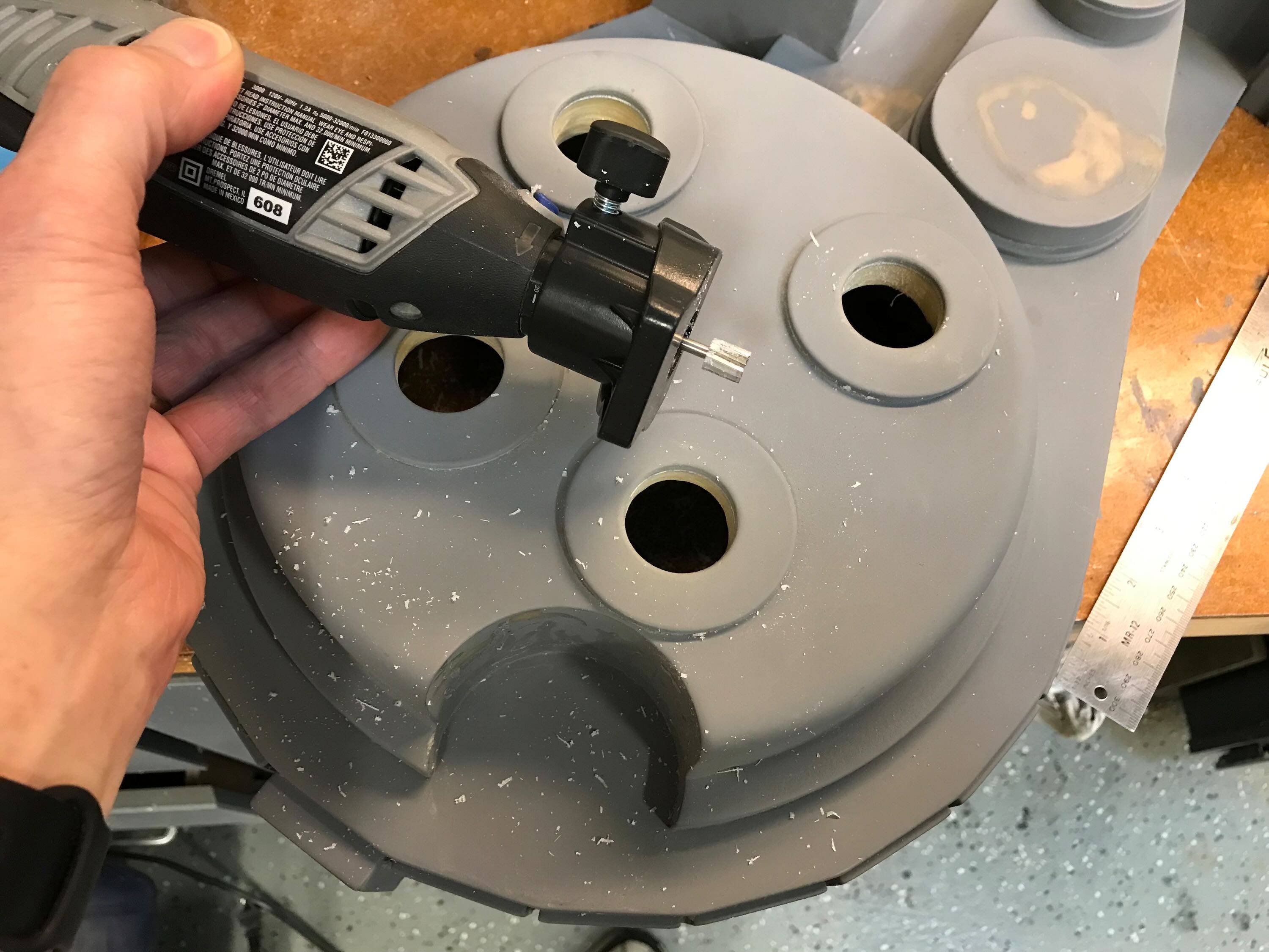
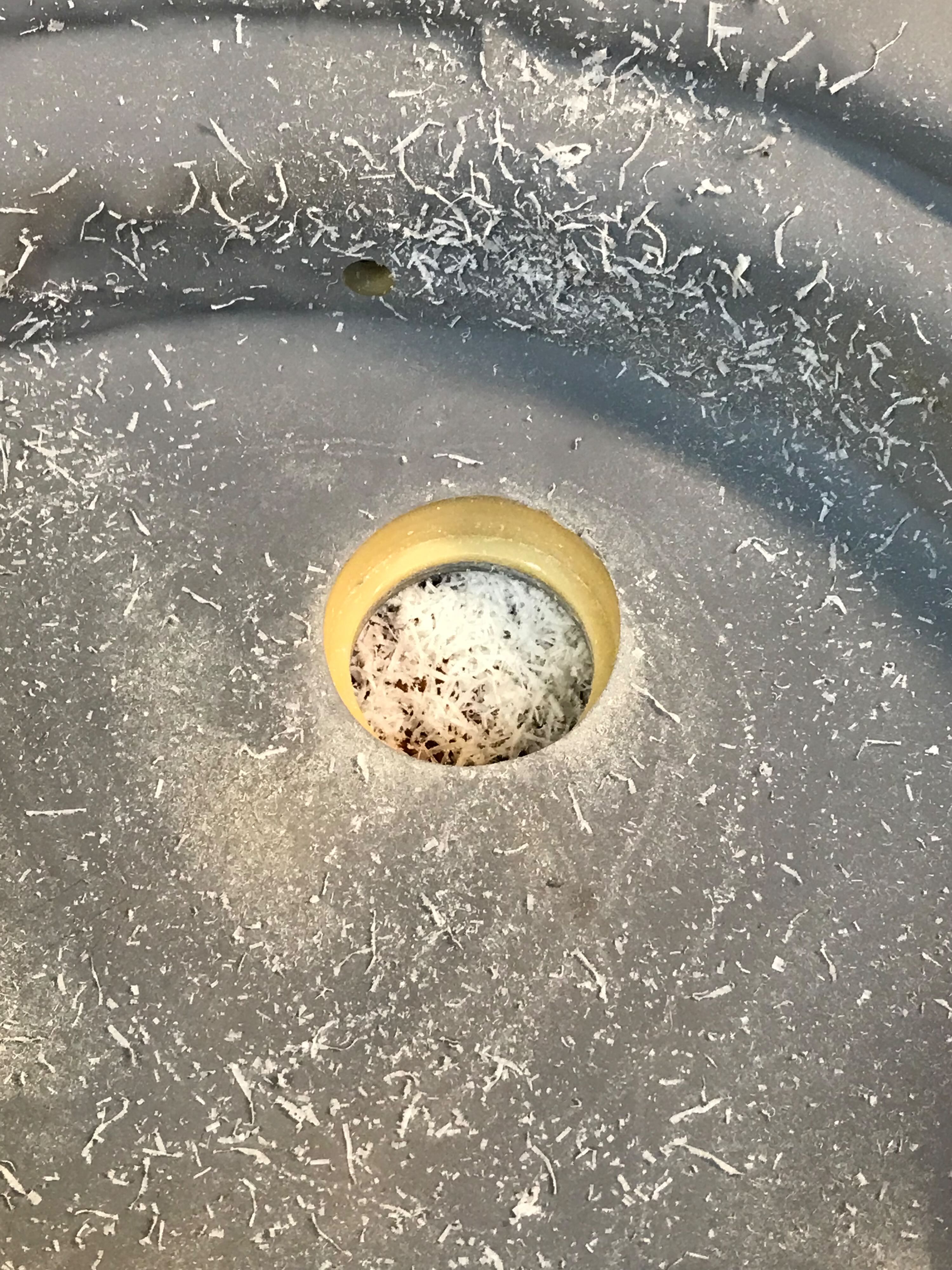
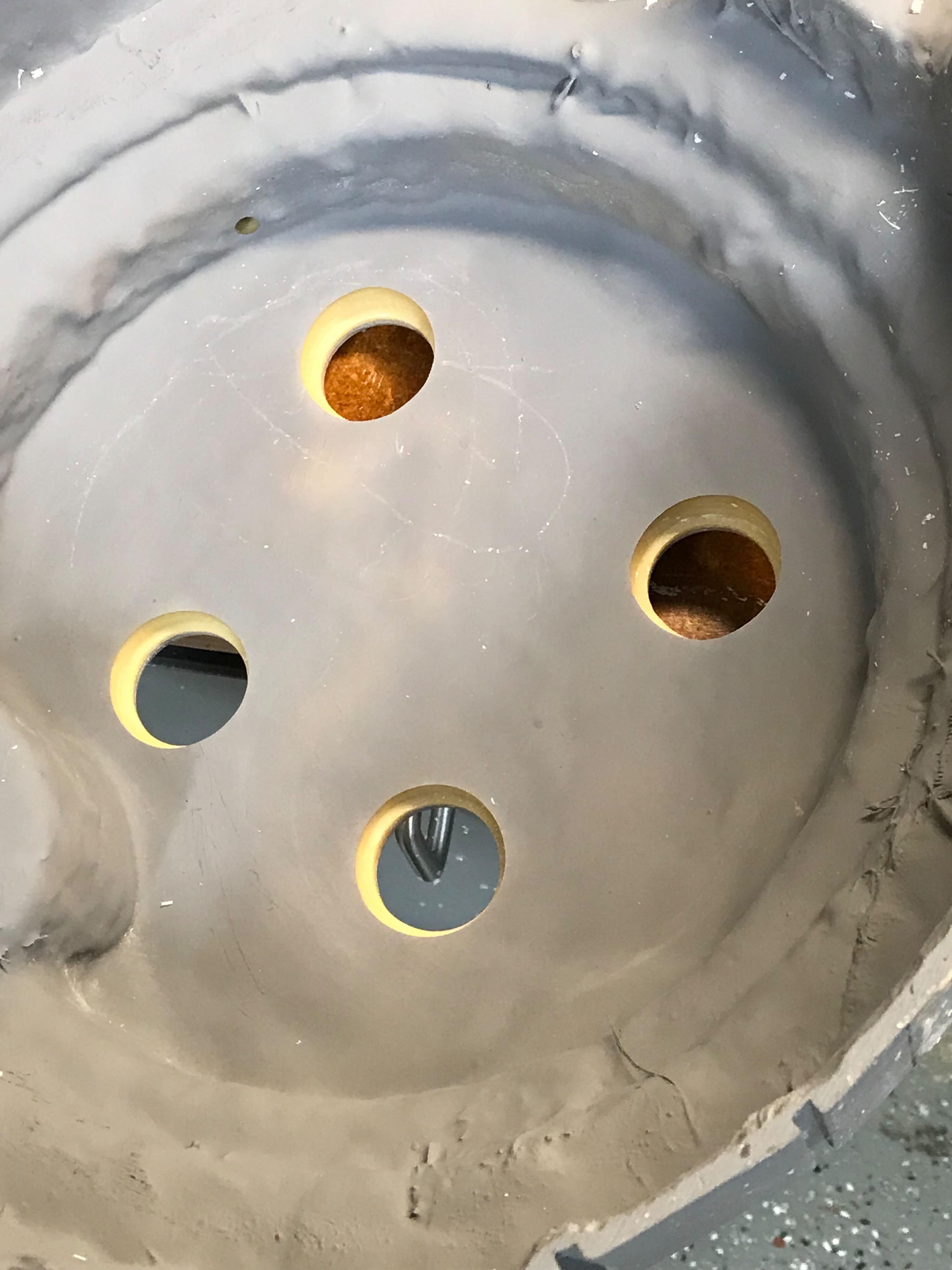
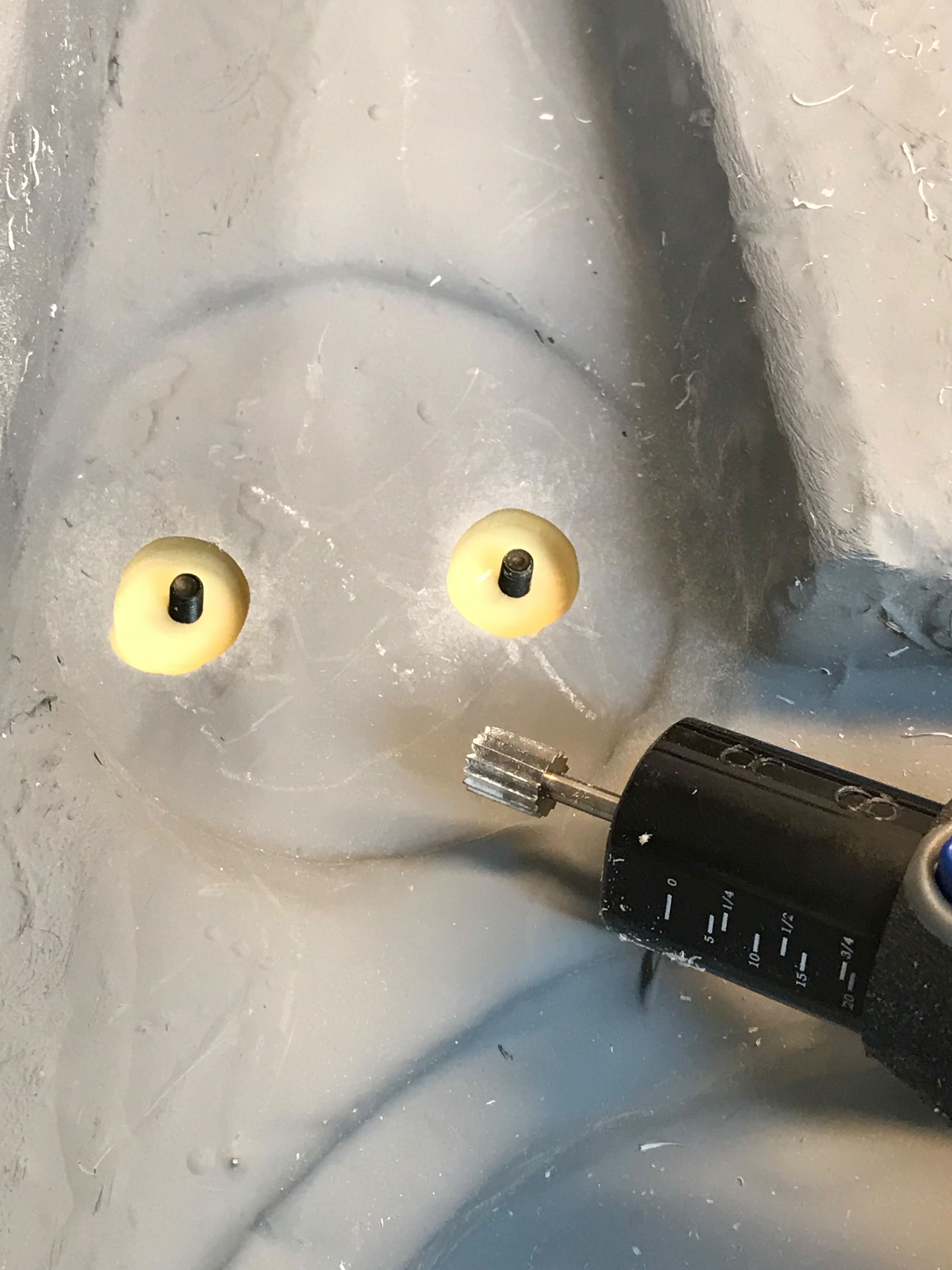
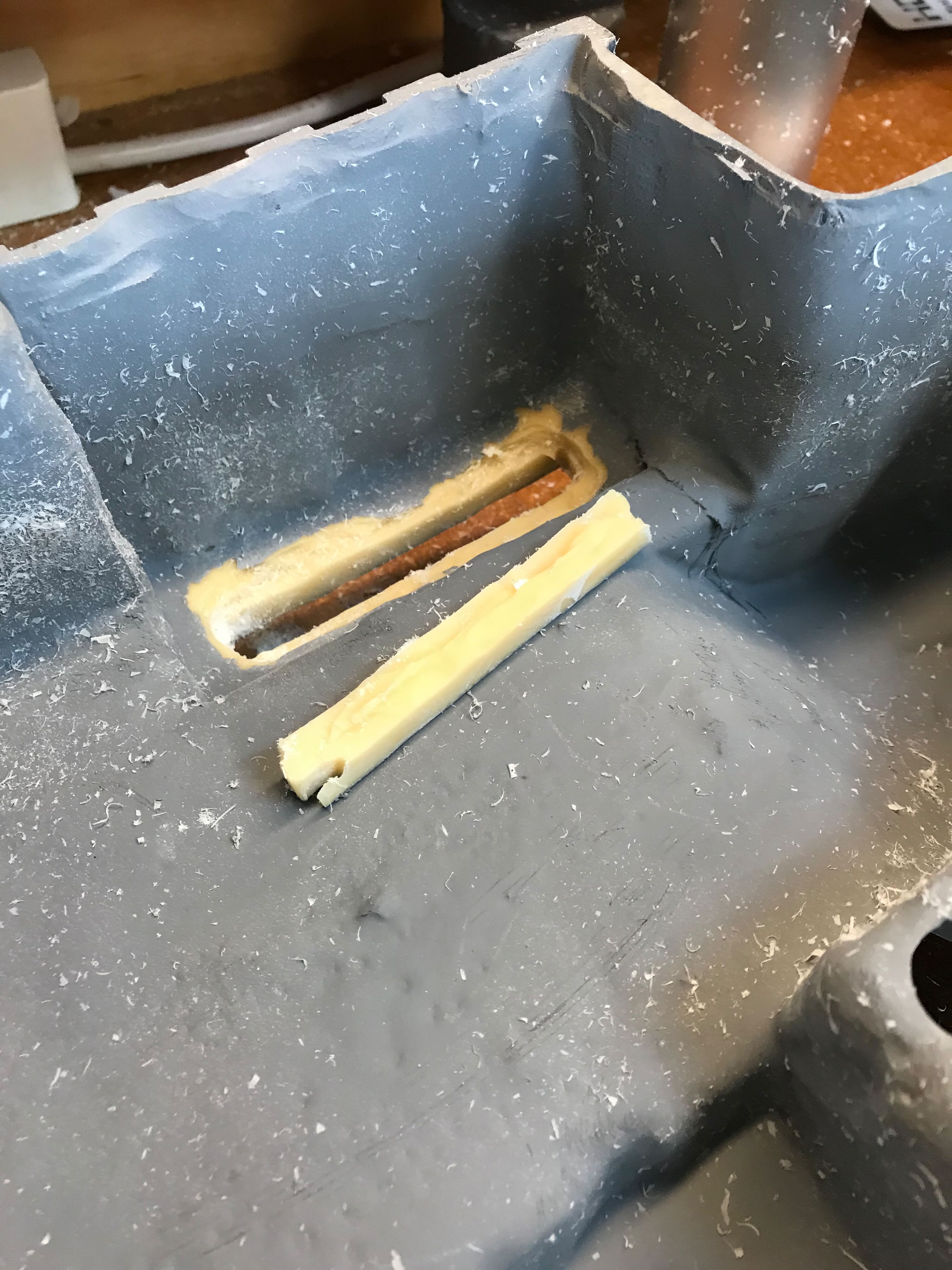
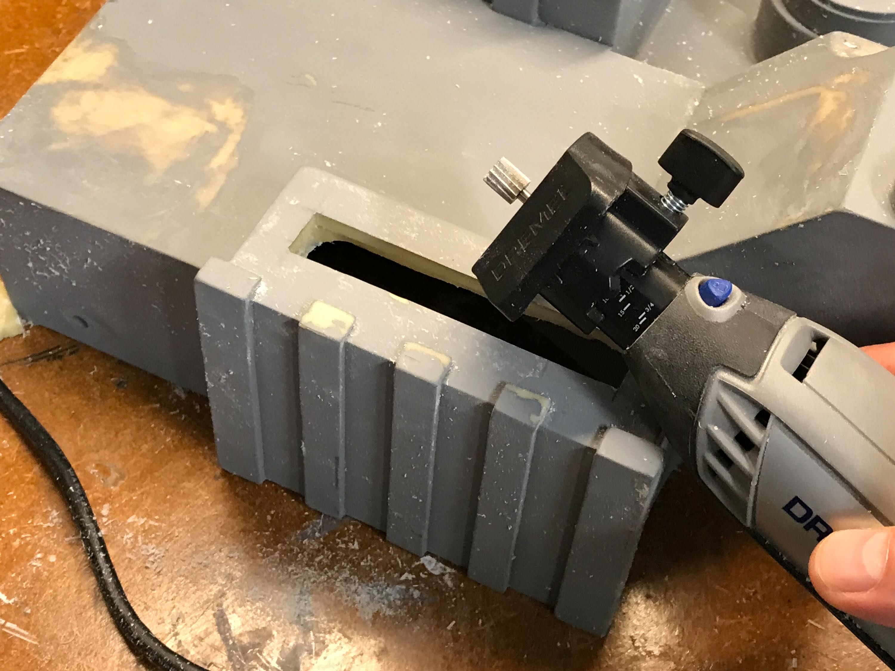
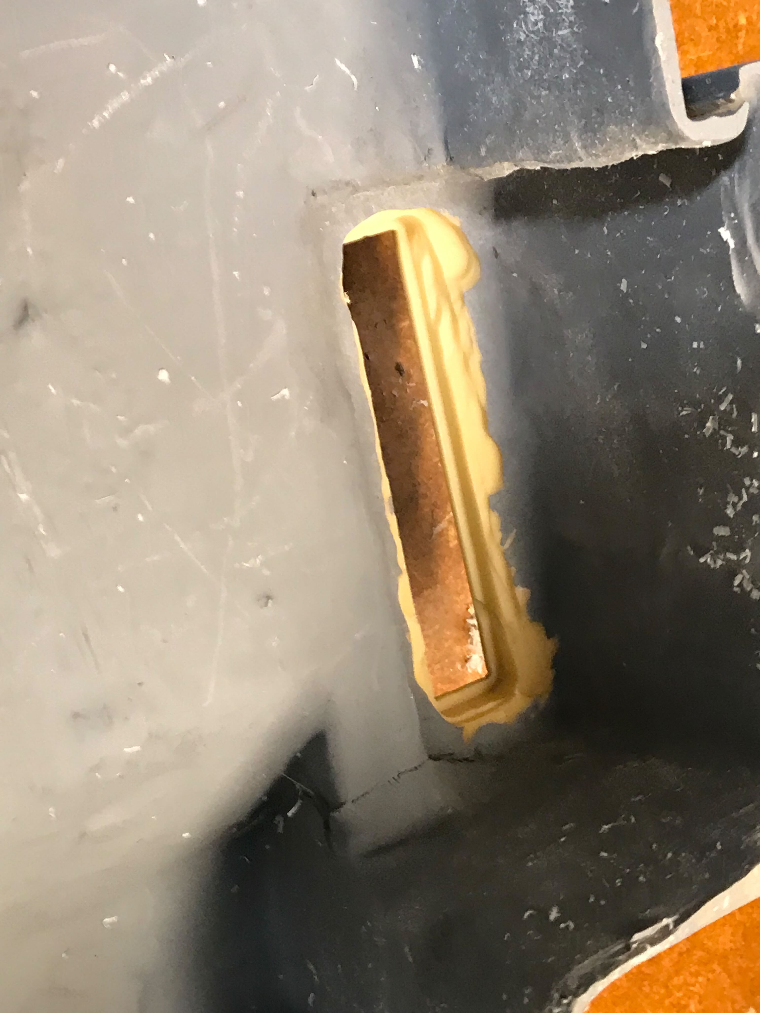
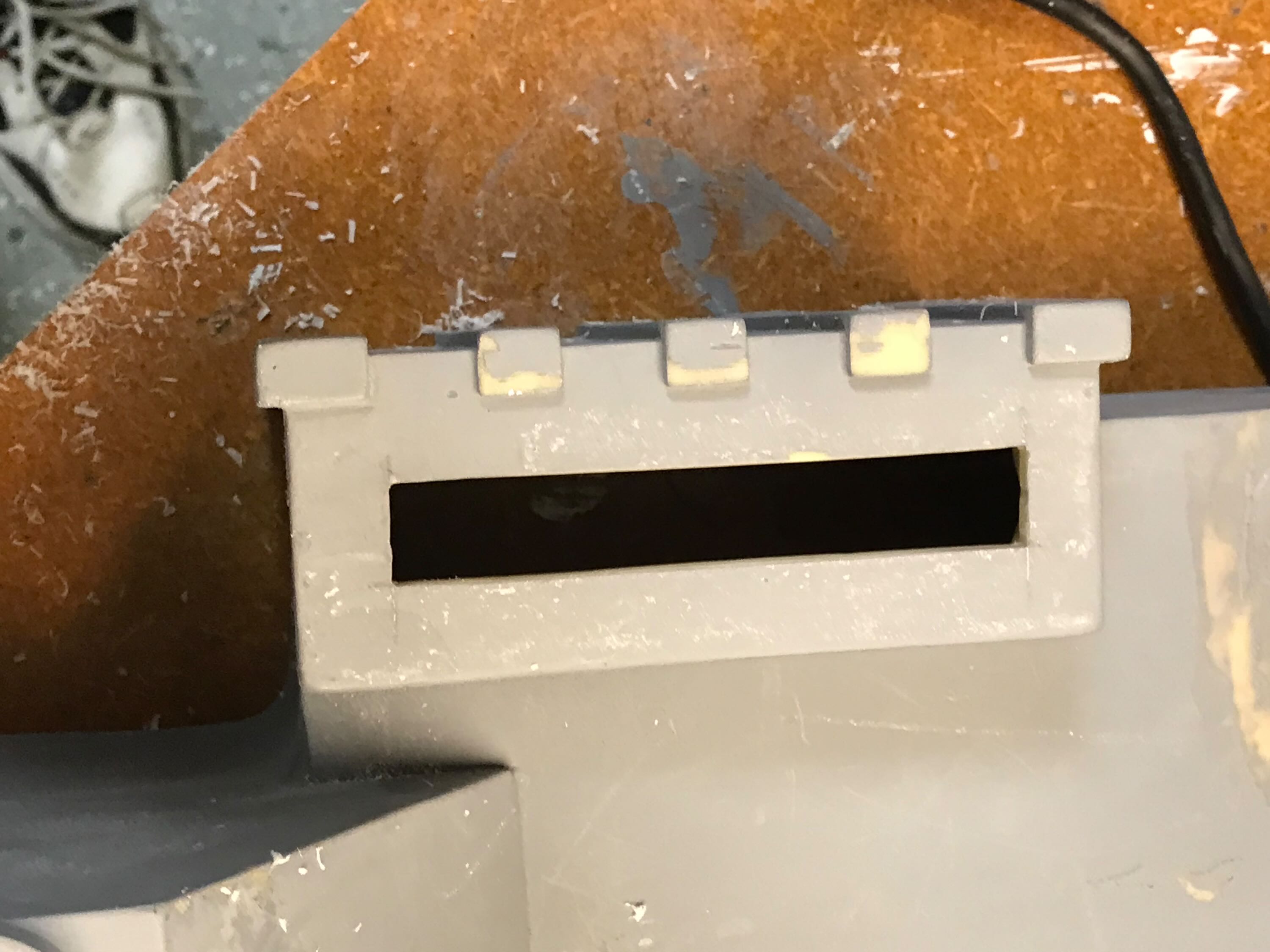
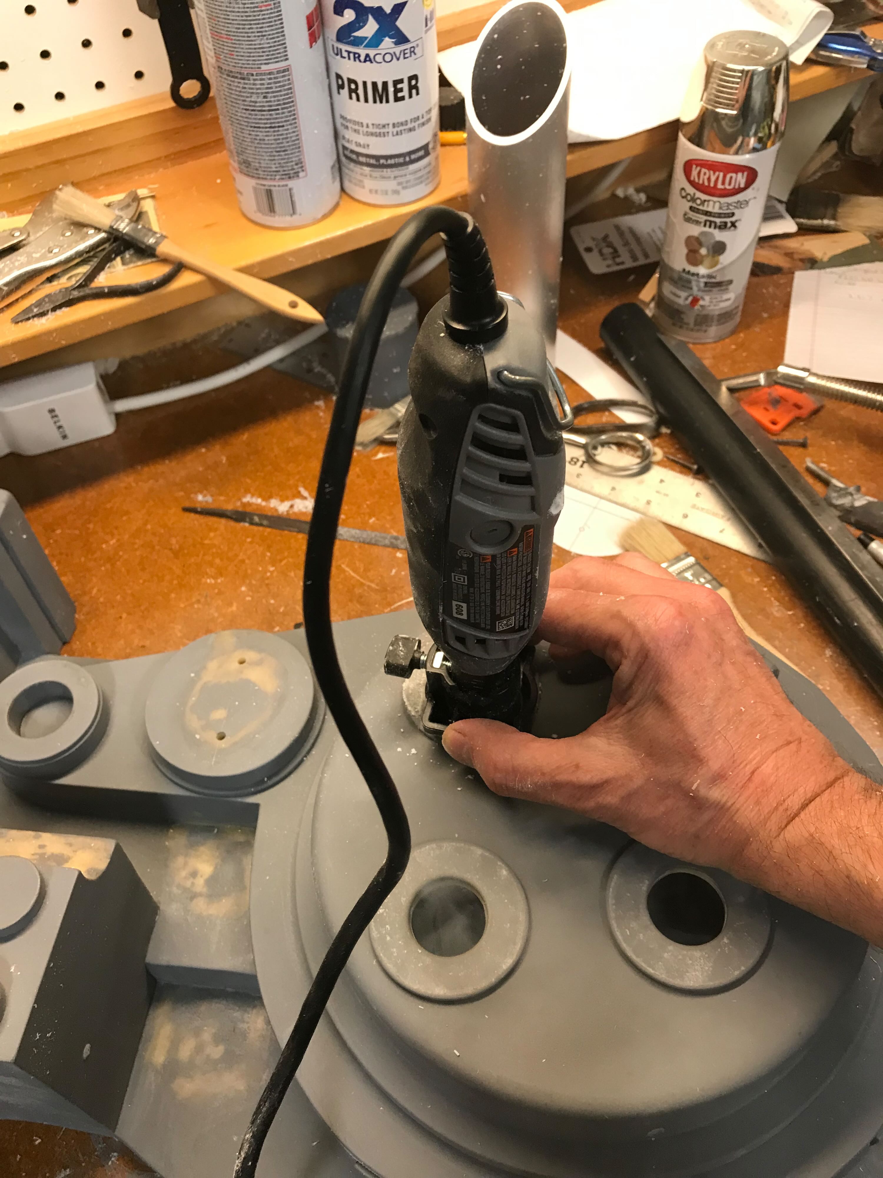
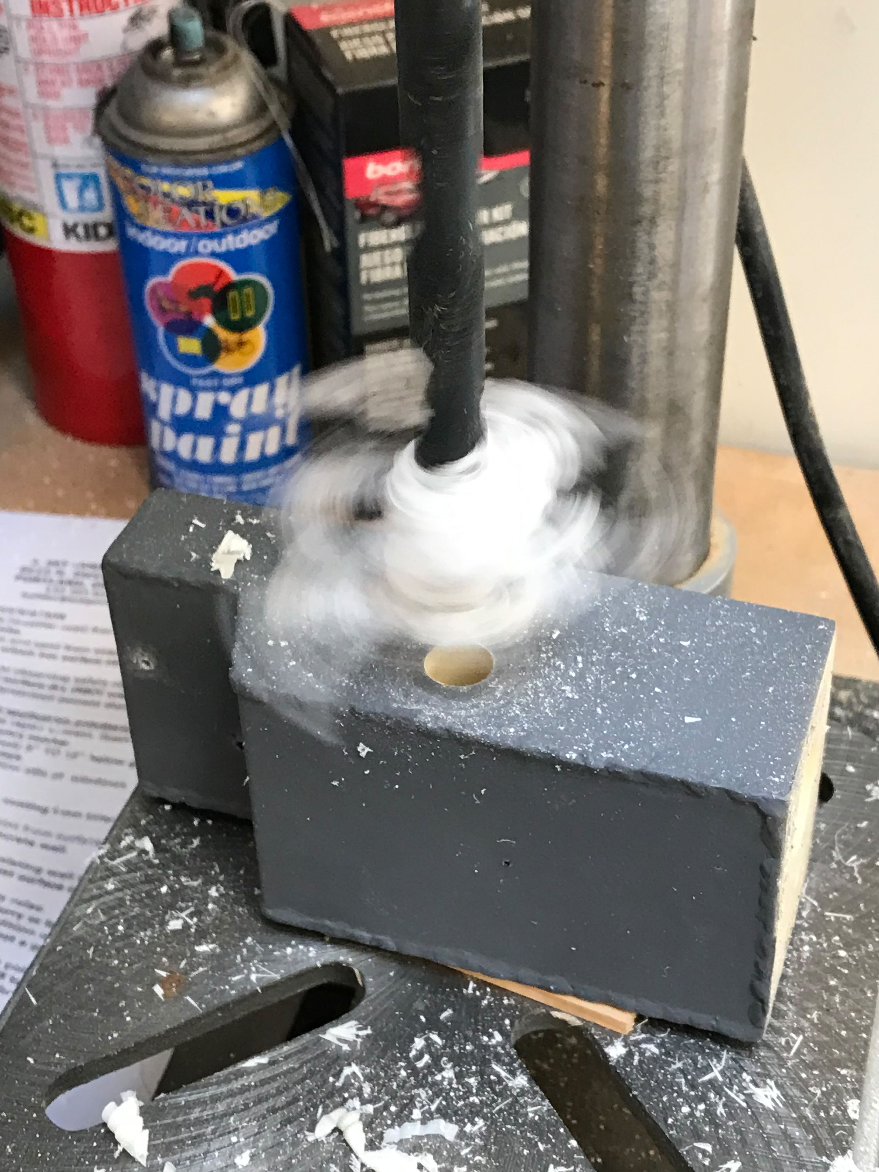
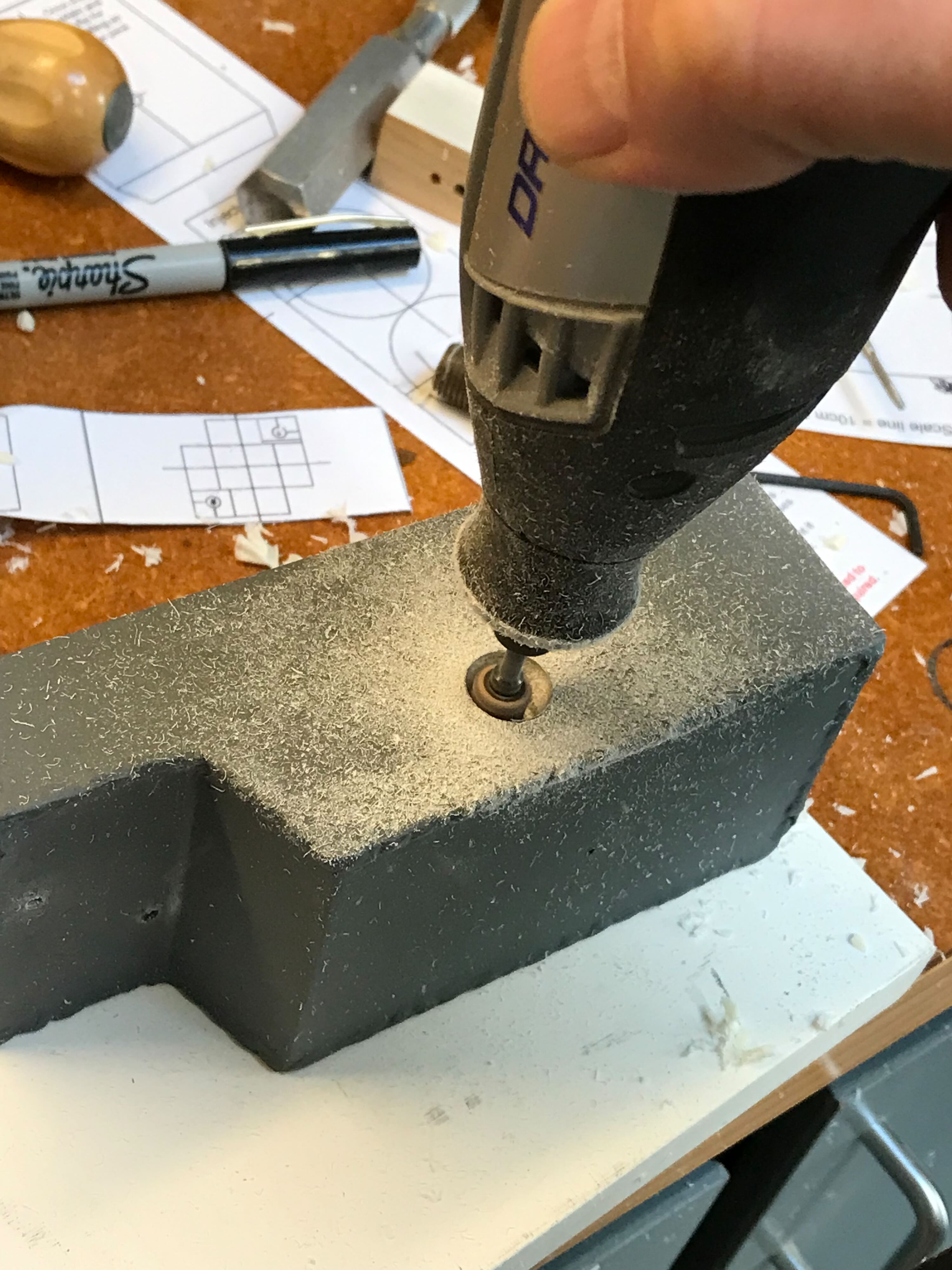
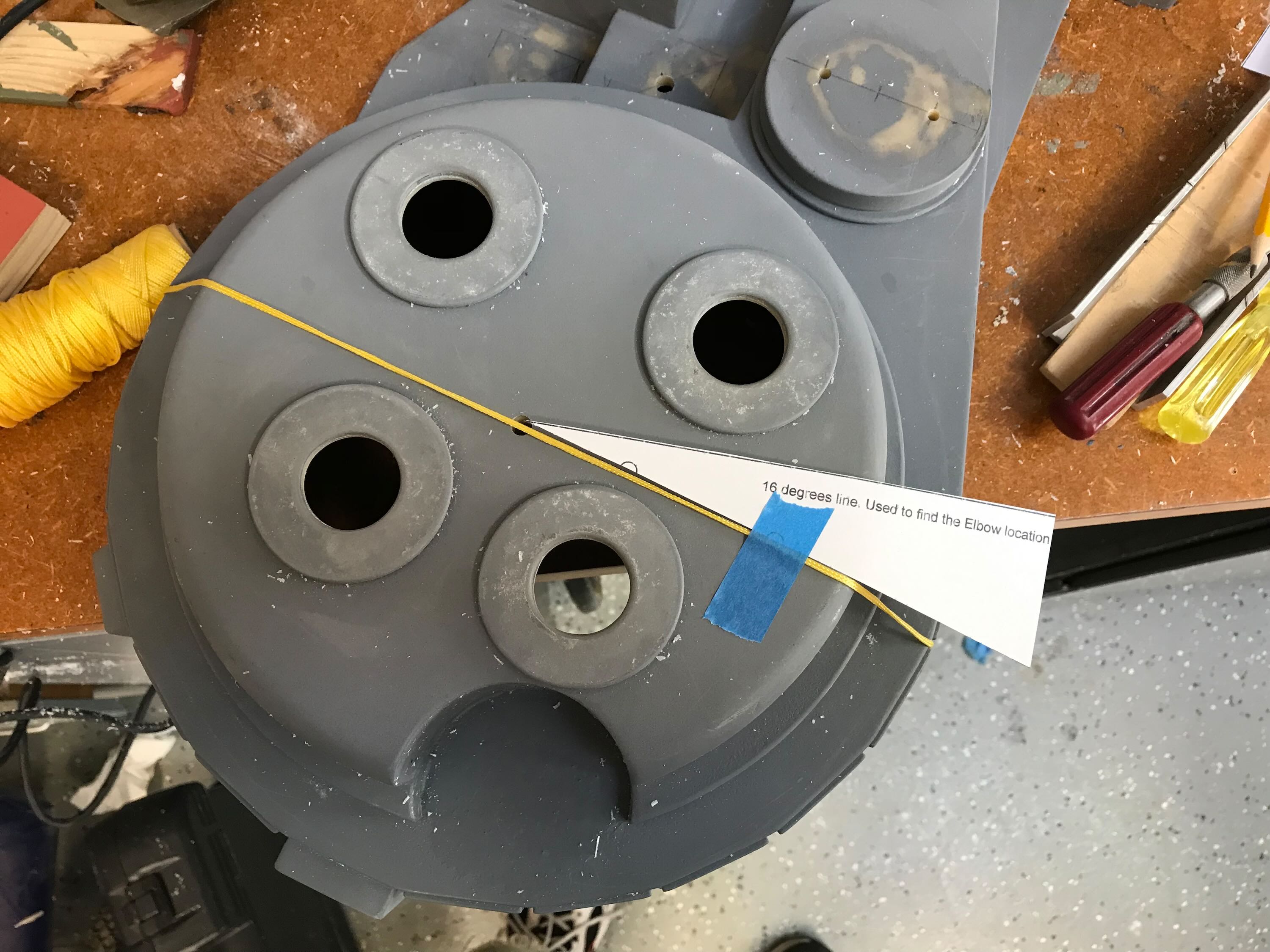
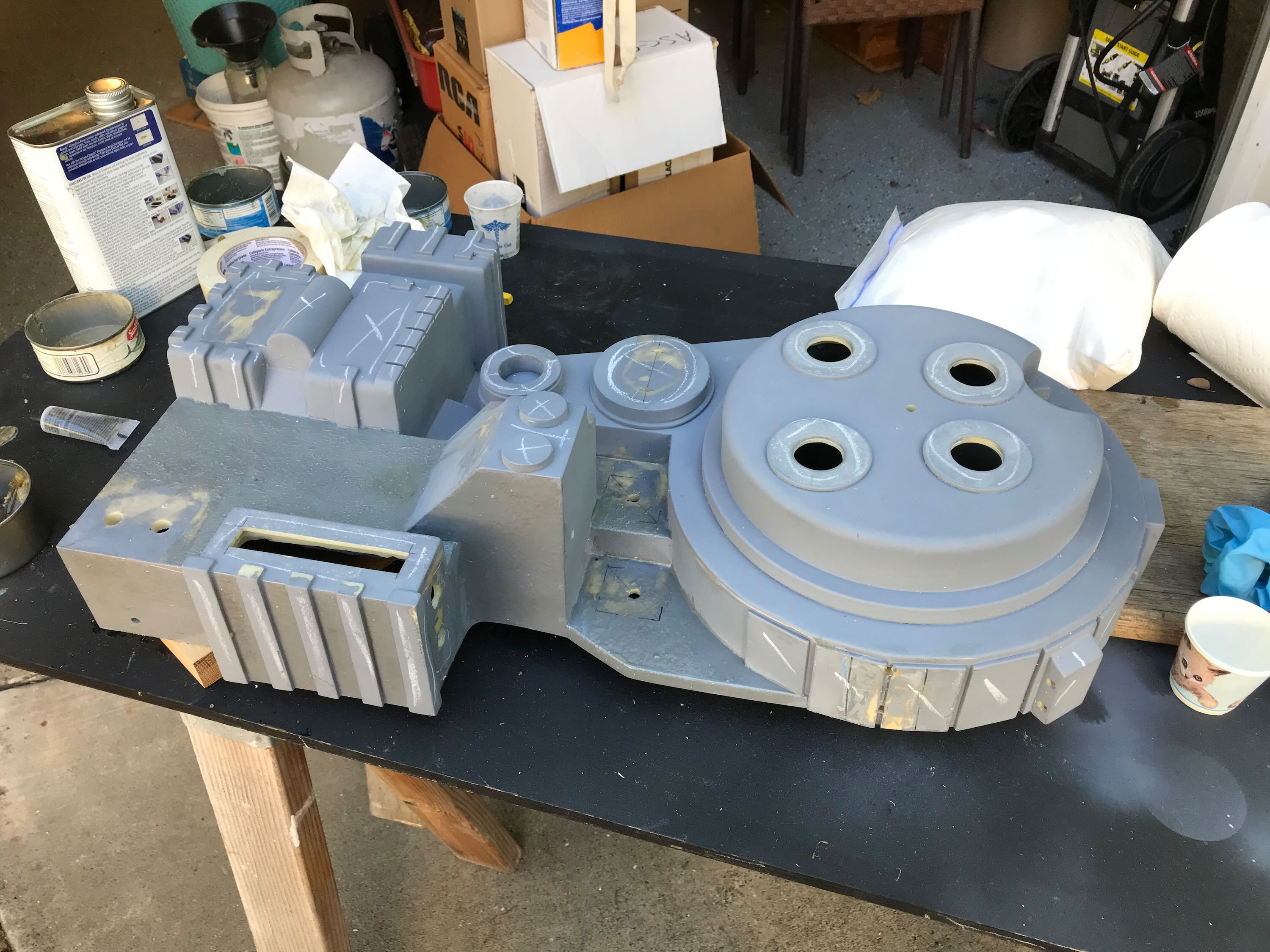
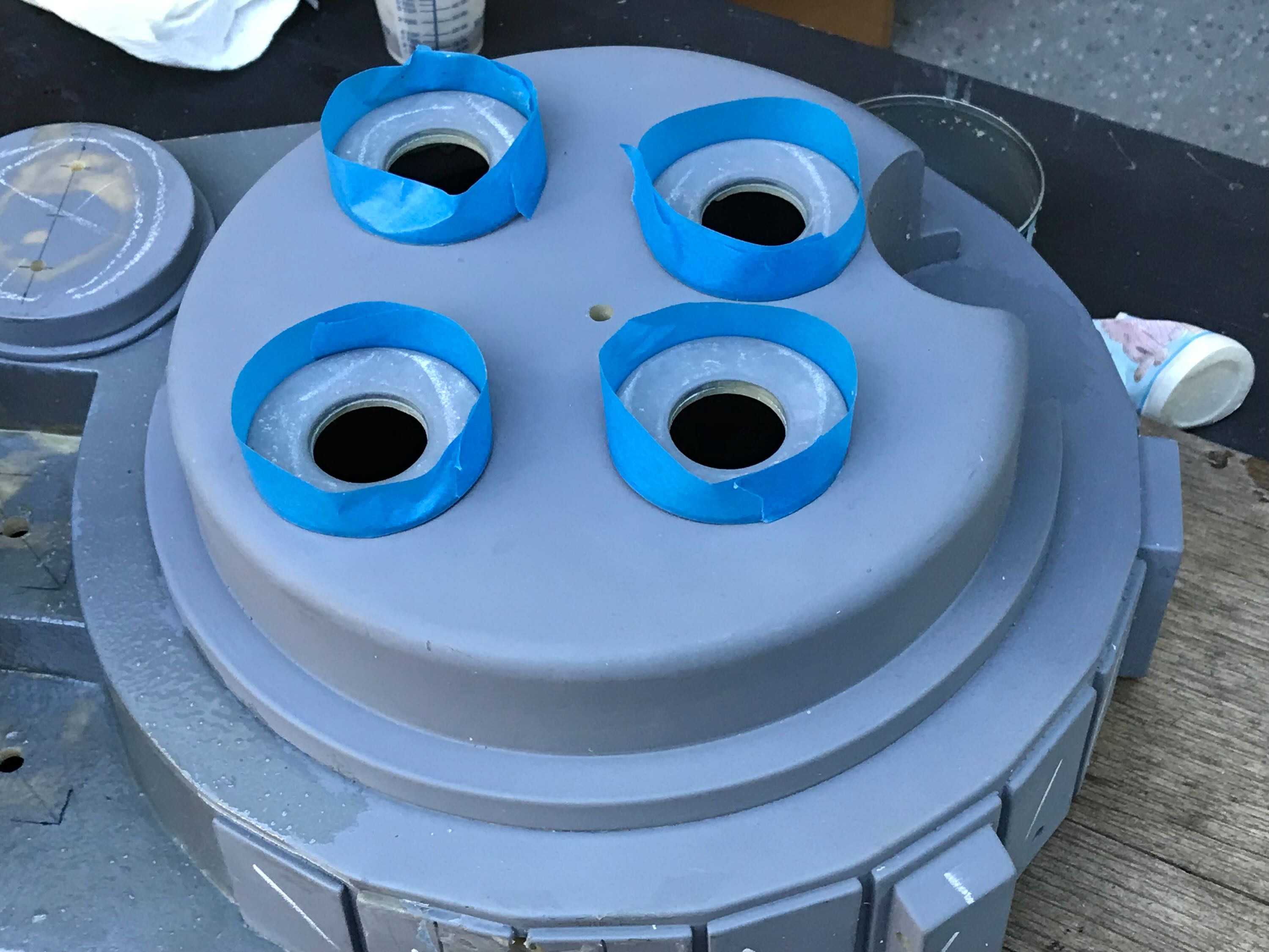
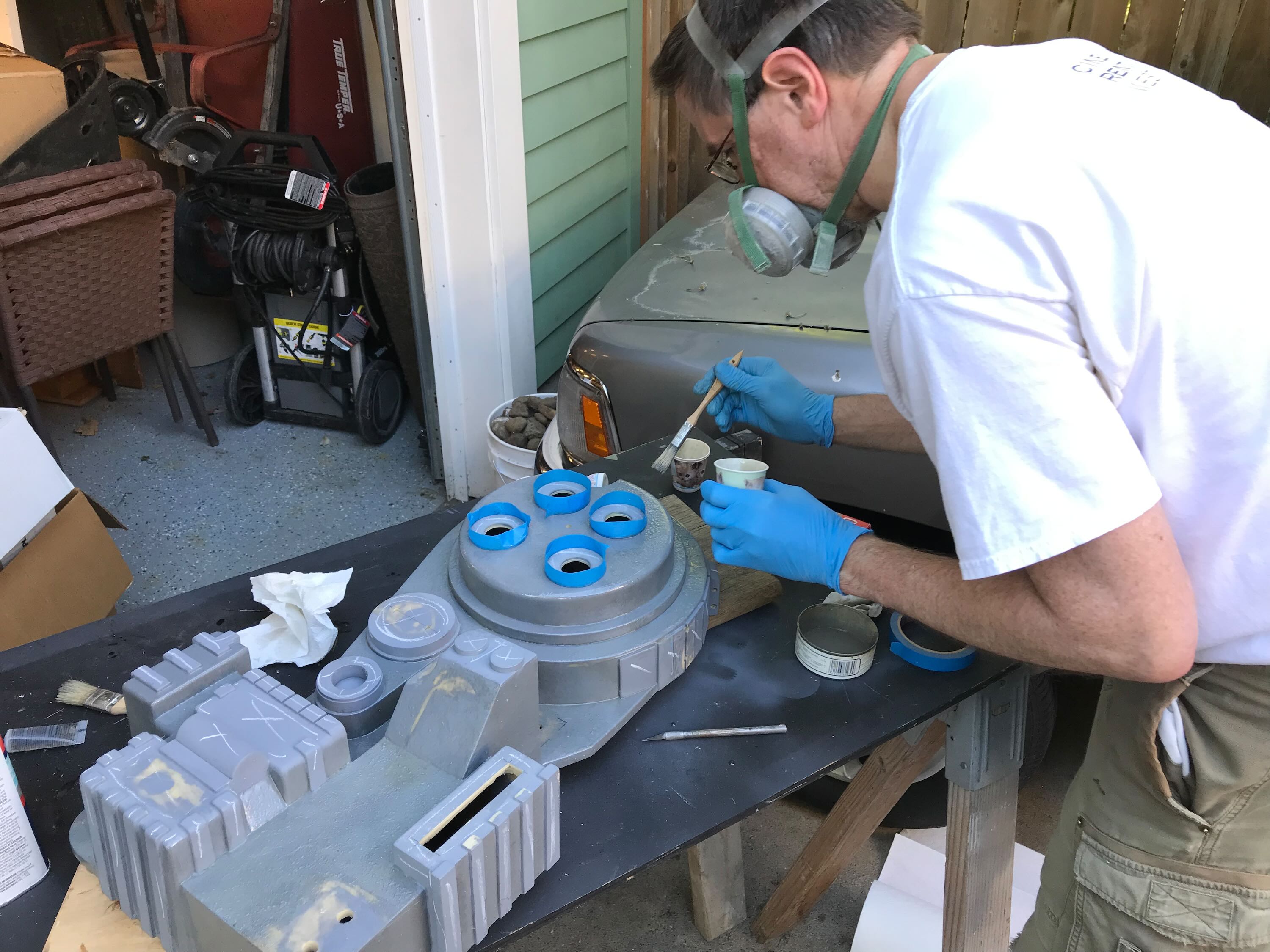
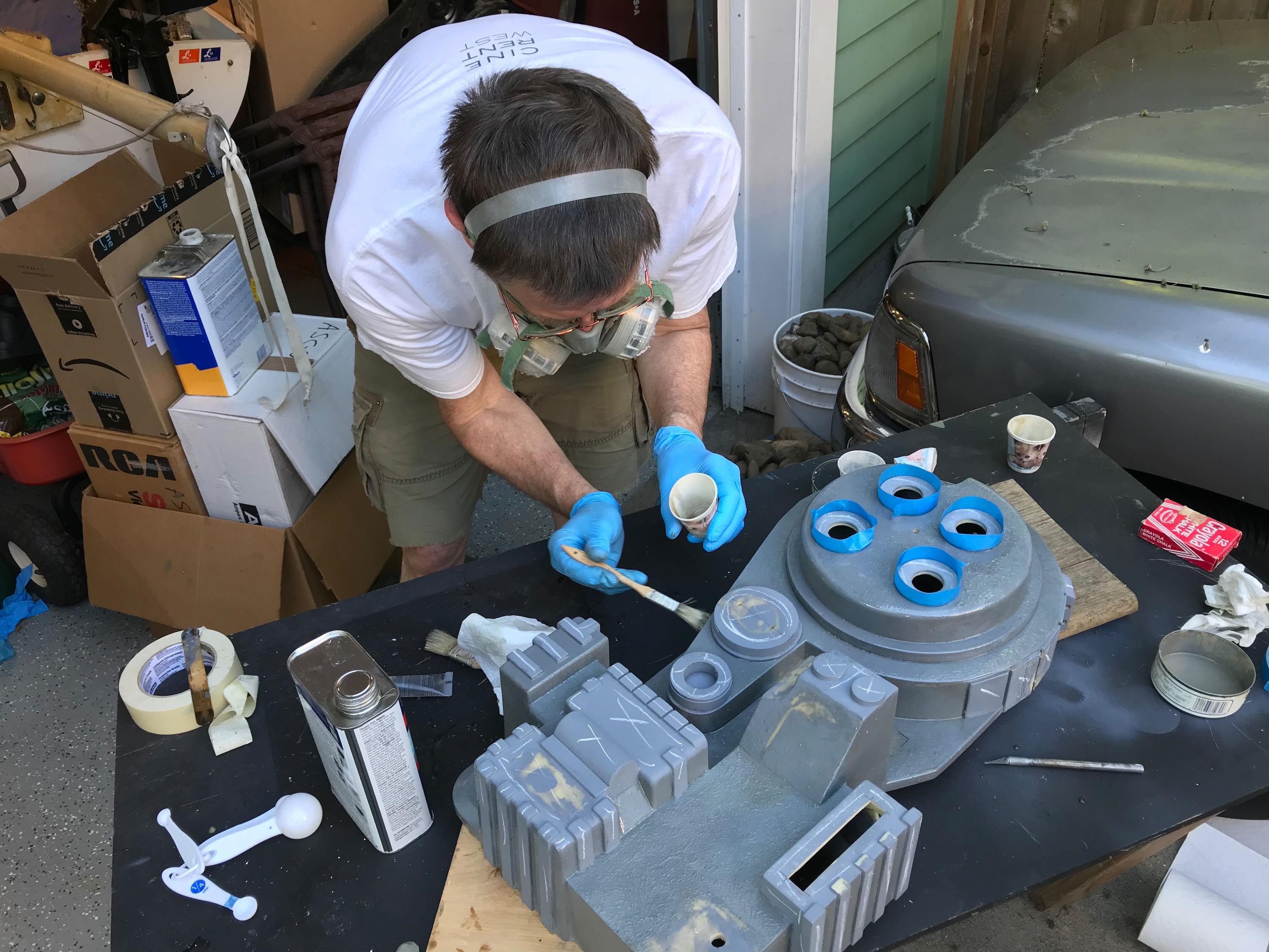
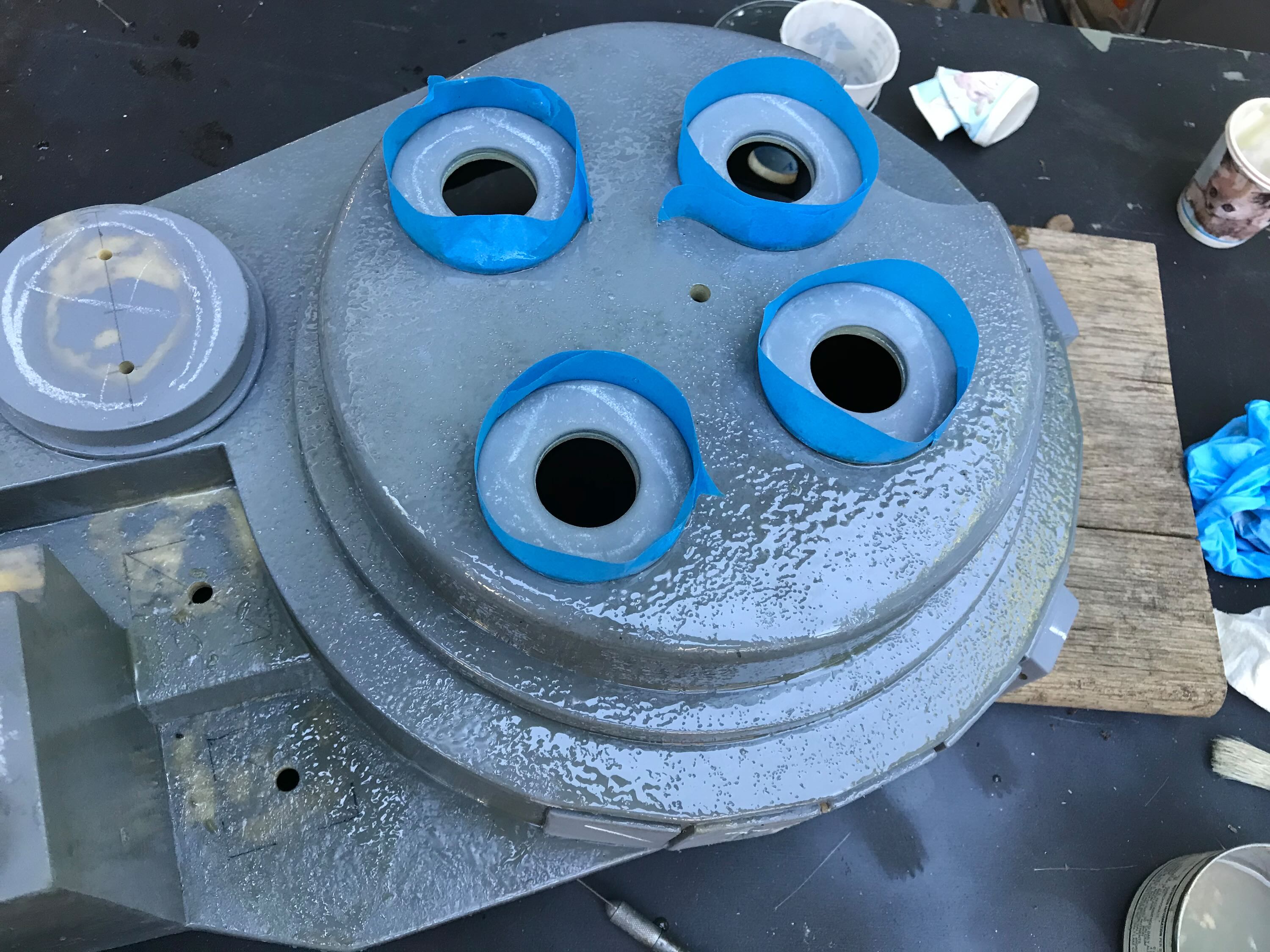
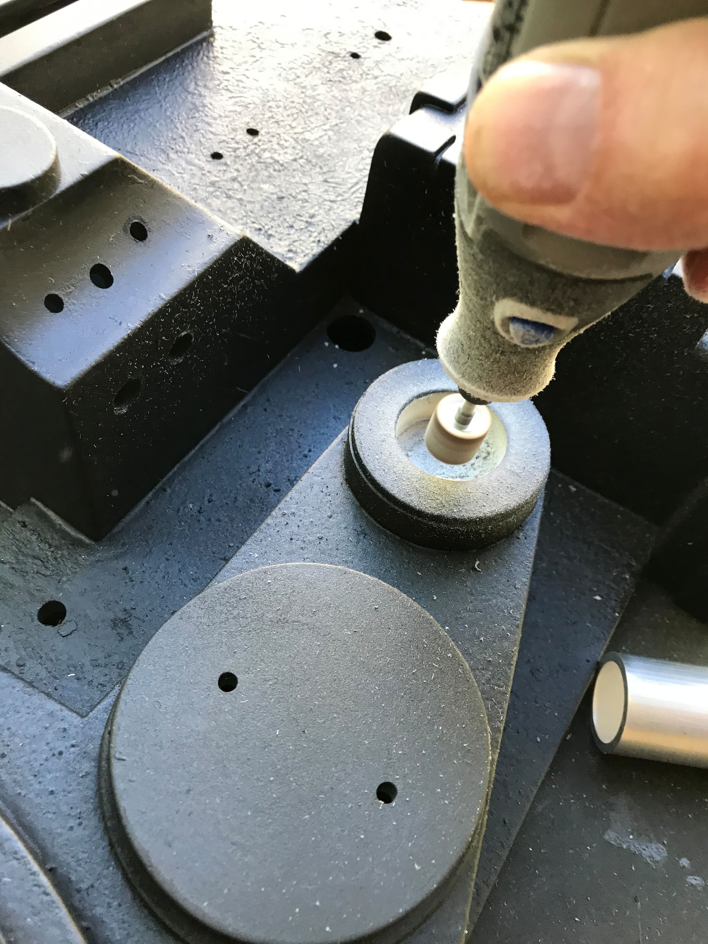
This BoK Props kit has a lot of variation in the thickness of the resin. This variation will be visible in openings, so I have to thin out the material around those openings to create an even, machined look. For the holes in the cyclotron I used a sanding/grinding attachment that came with my Dremel tool to keep a carving bit an even distance from the face of the holes.
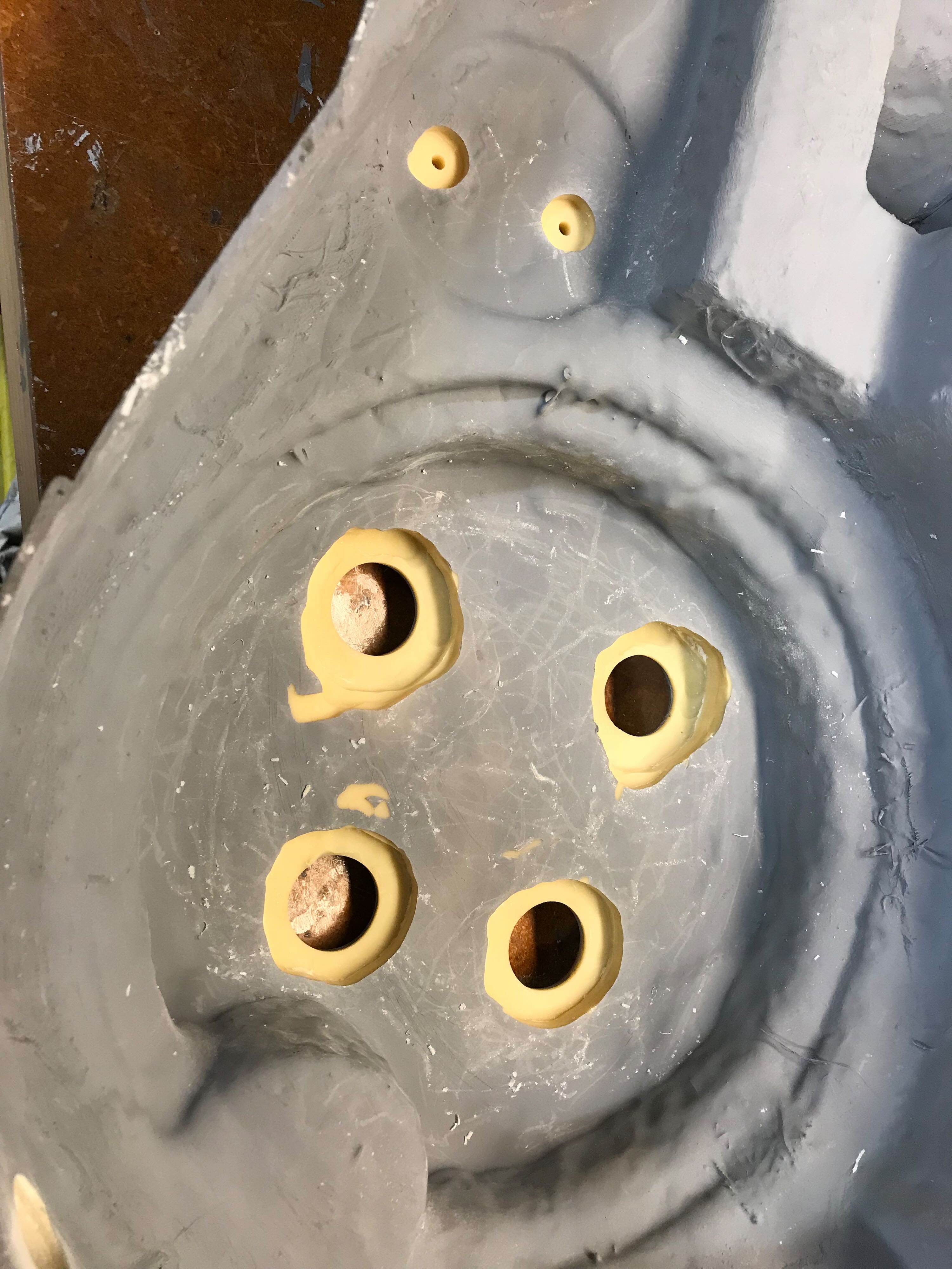
That carving bit only gives me a clean edge of around 1/8". I’ll decide later whether I need to route out more resin from the inside to accommodate the lenses.
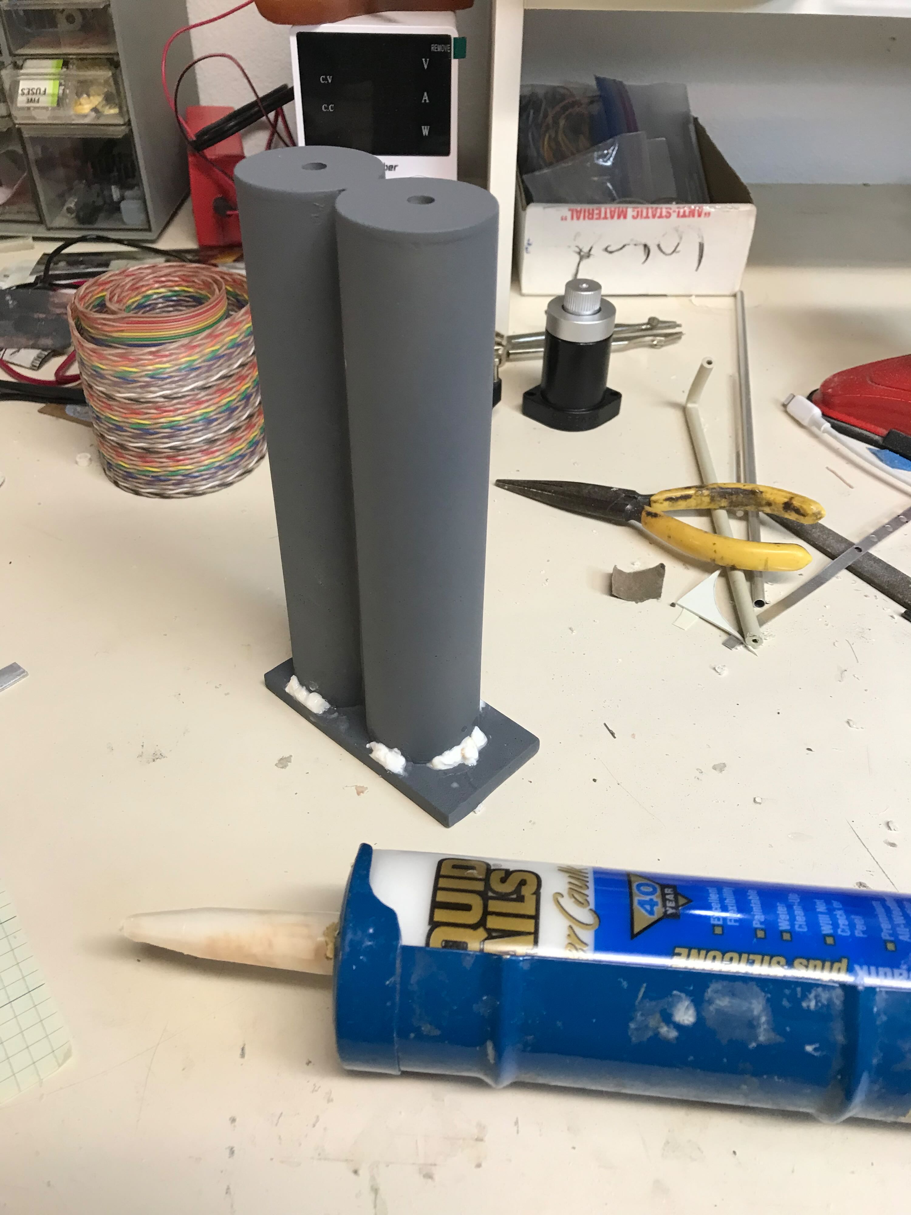
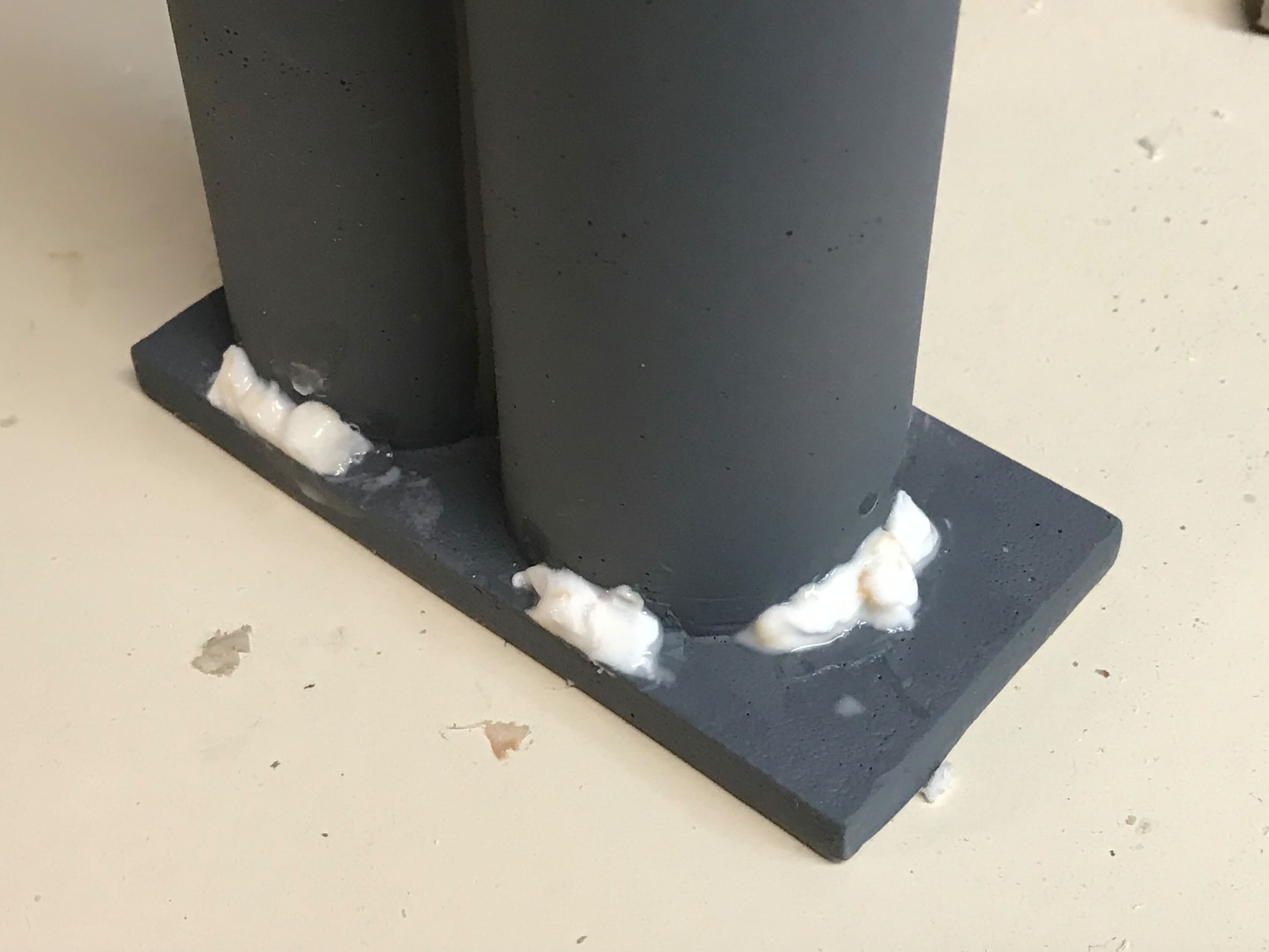
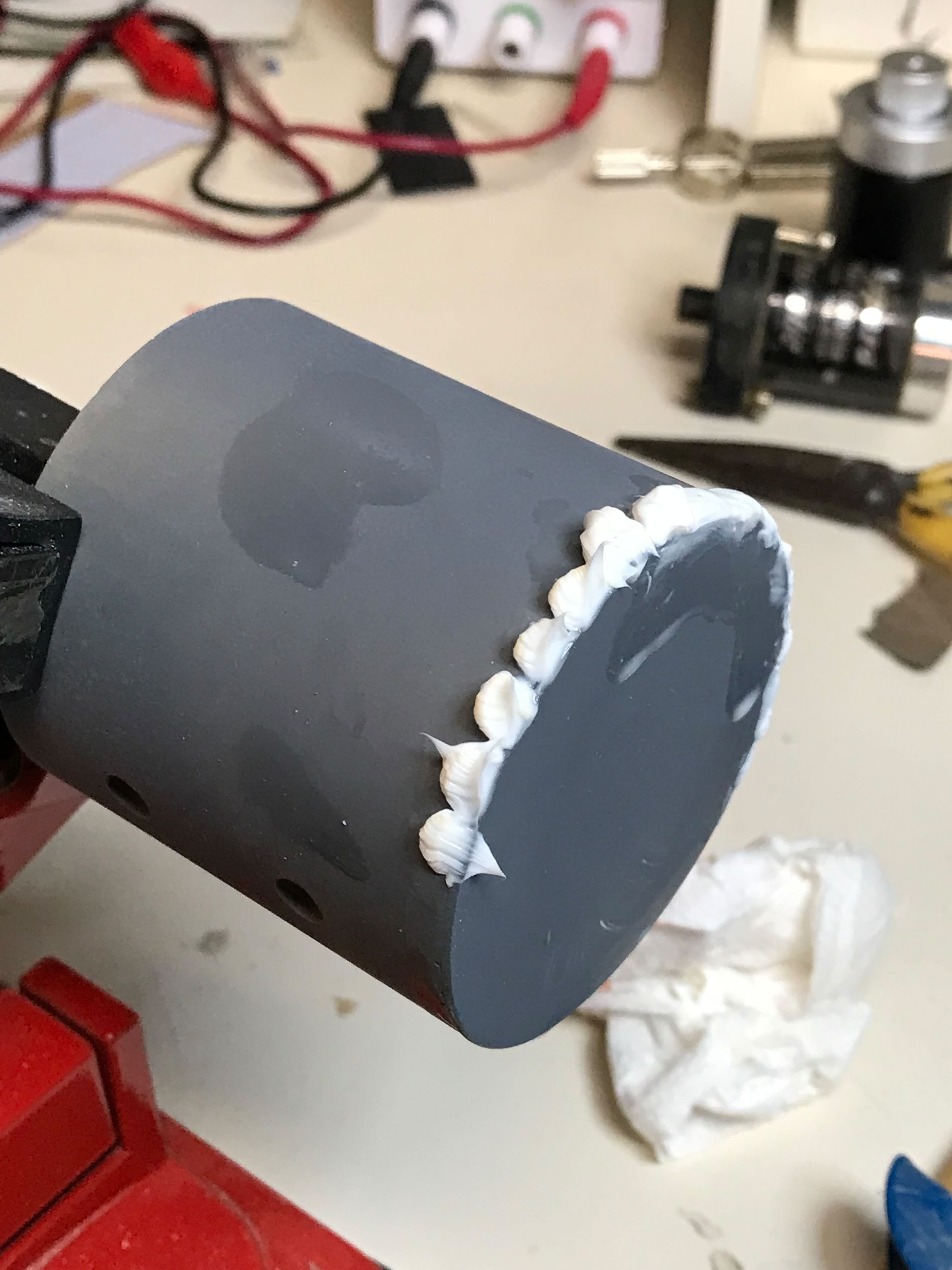
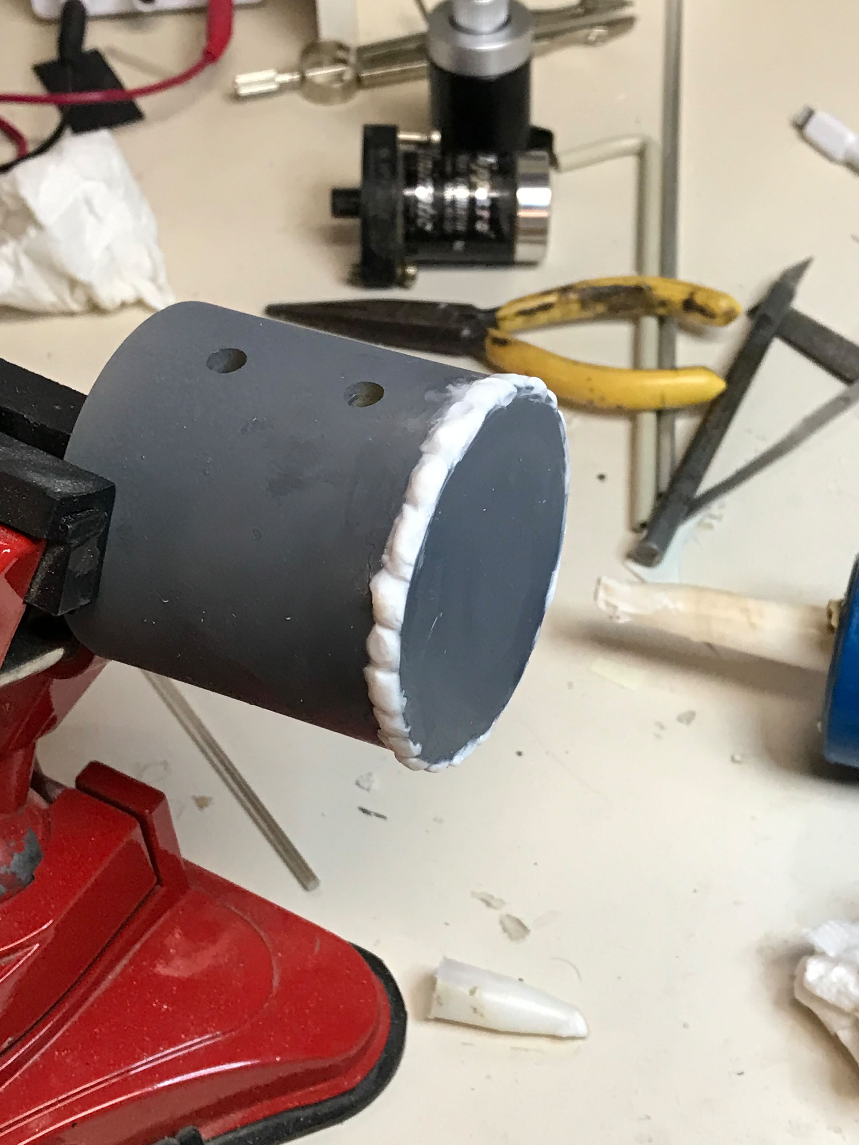
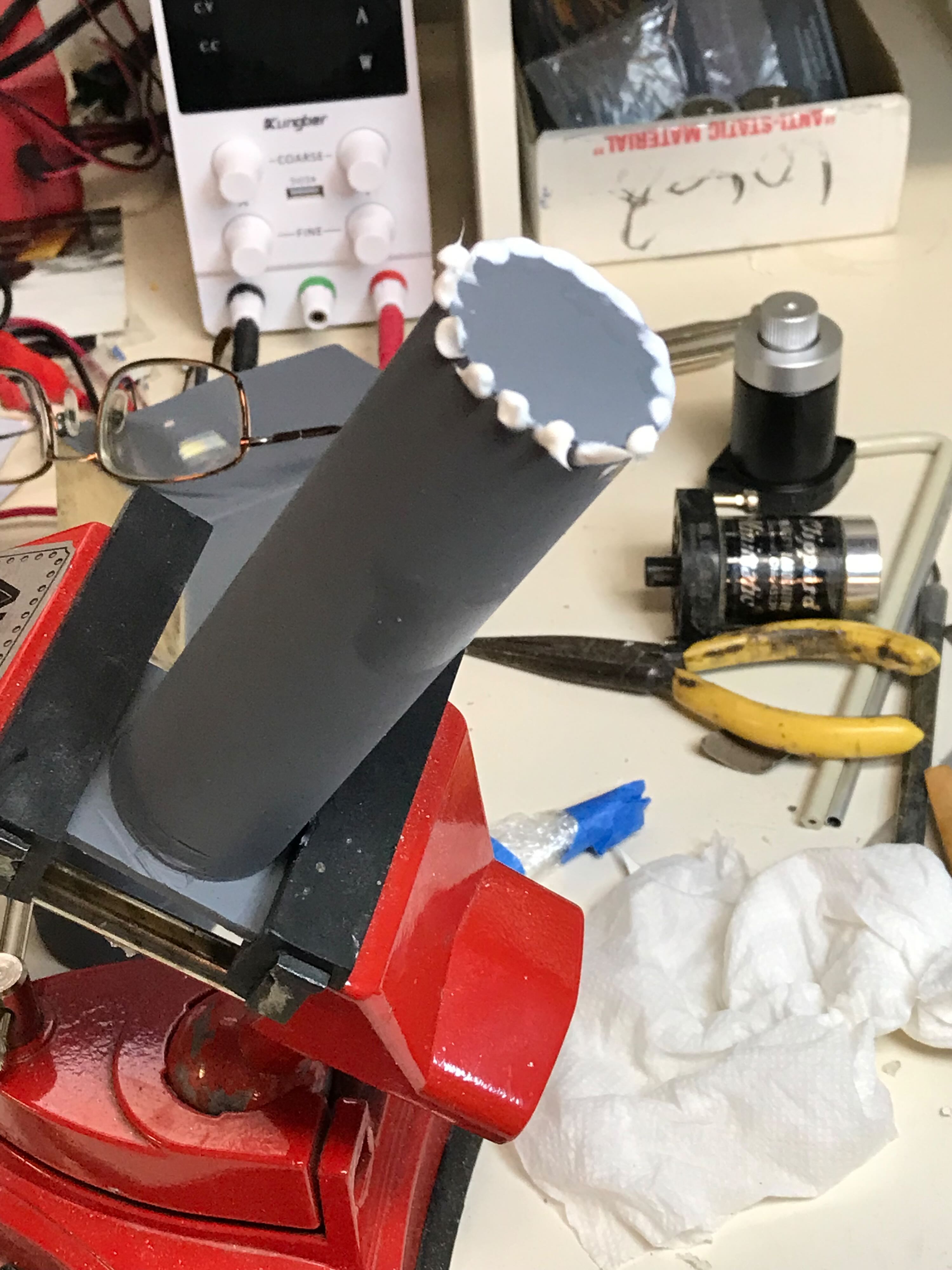
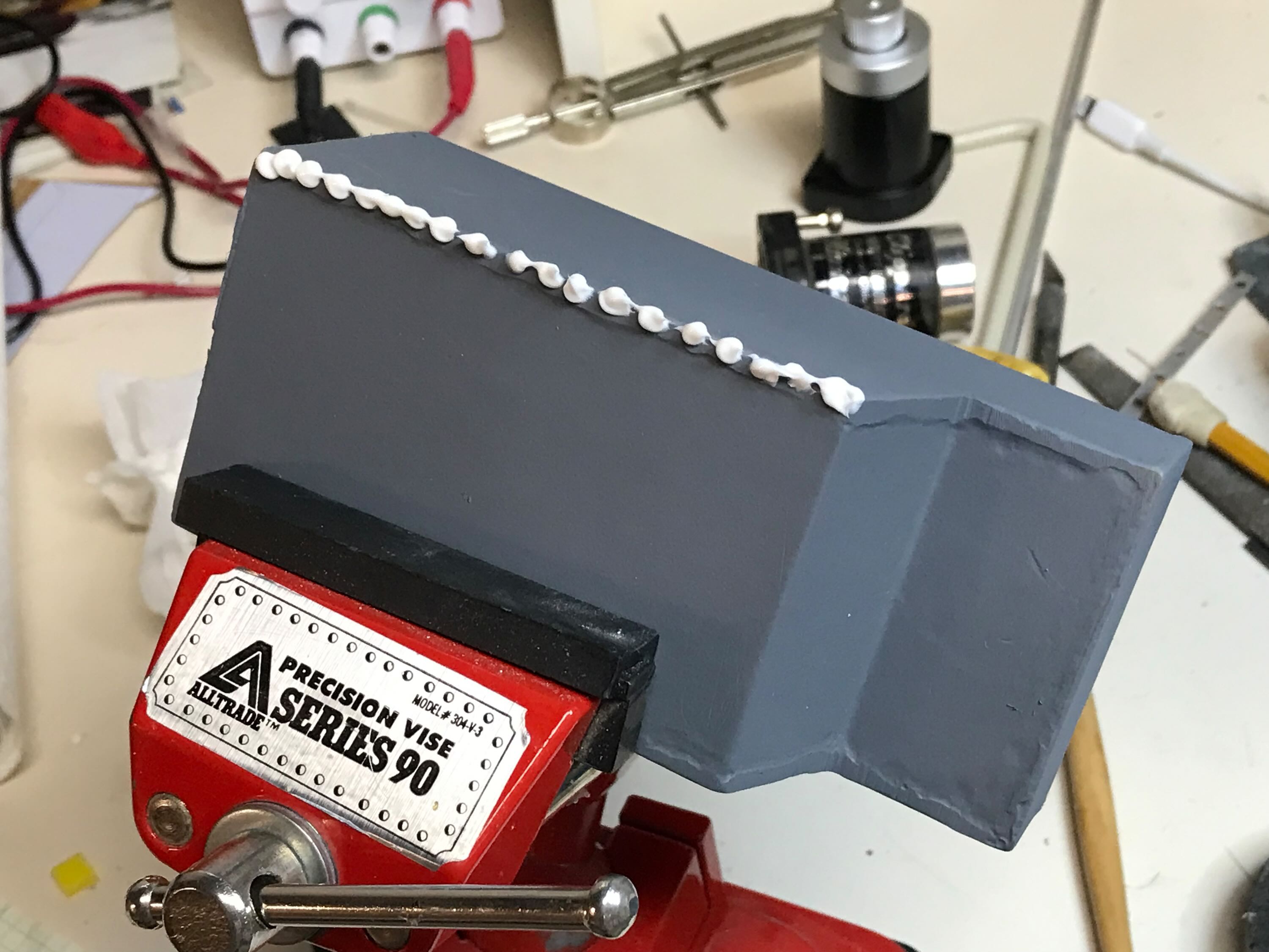
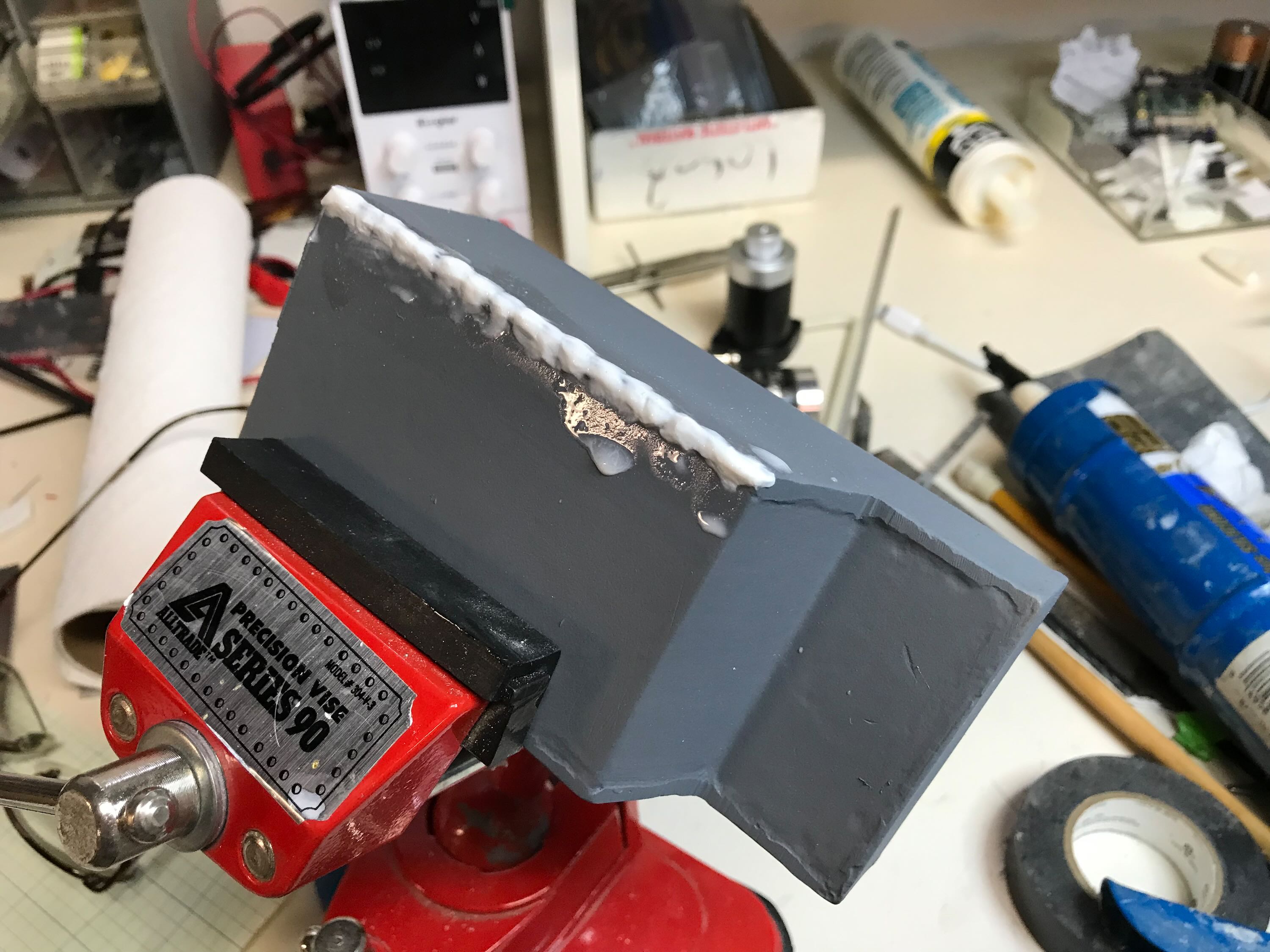
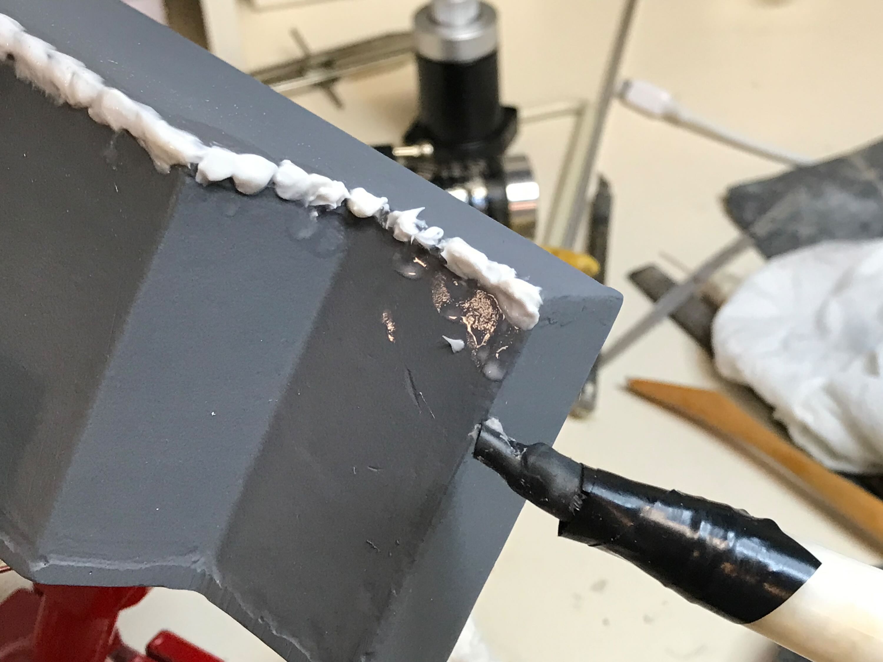
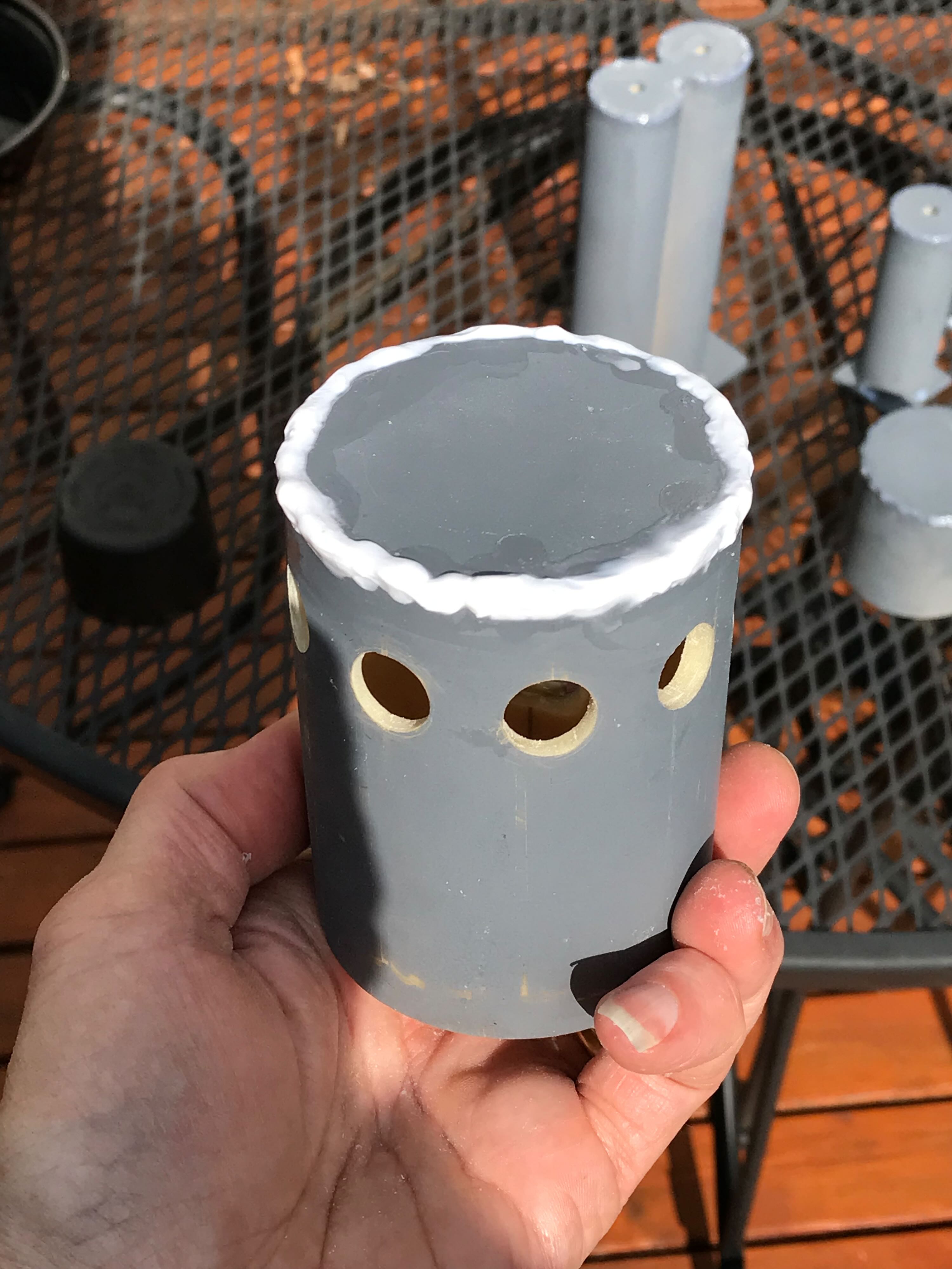
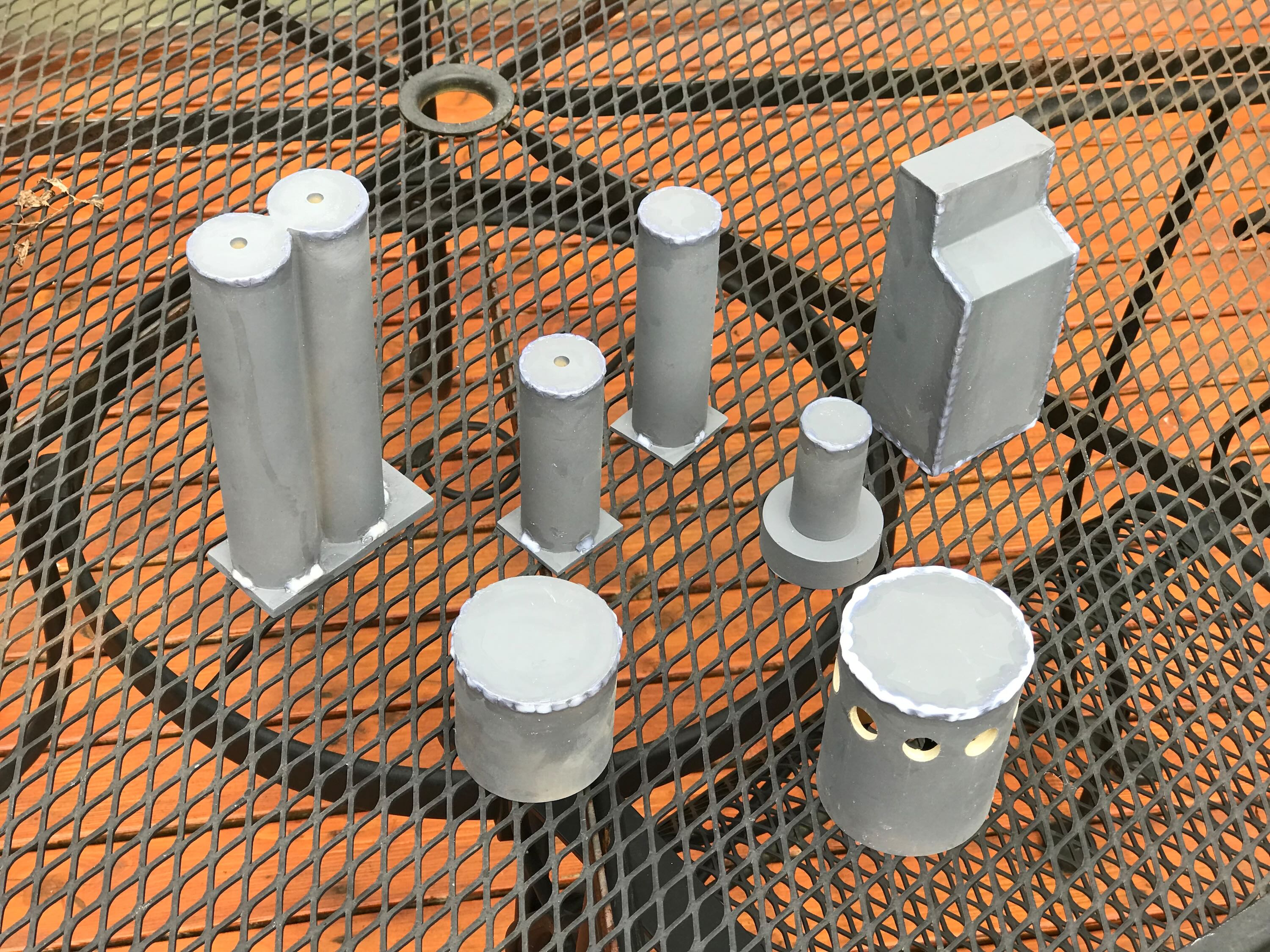
6/16/22 AFAIK this BoK Props kit had welds incorporated into the resin parts, but for whatever reason those had been removed before I got it. So I set out to quickly create decent facsimiles. I didn’t think putty would give me the look of flowing metal I wanted, and the filaments created by hot glue wouldn’t look good. I opted to go with a paintable silicone/latex caulk. I could apply it in dabs and use my wet finger to coax it into a something that could pass for a weld. I used some clear caulk I already had open. It’s white when wet and dries clear.
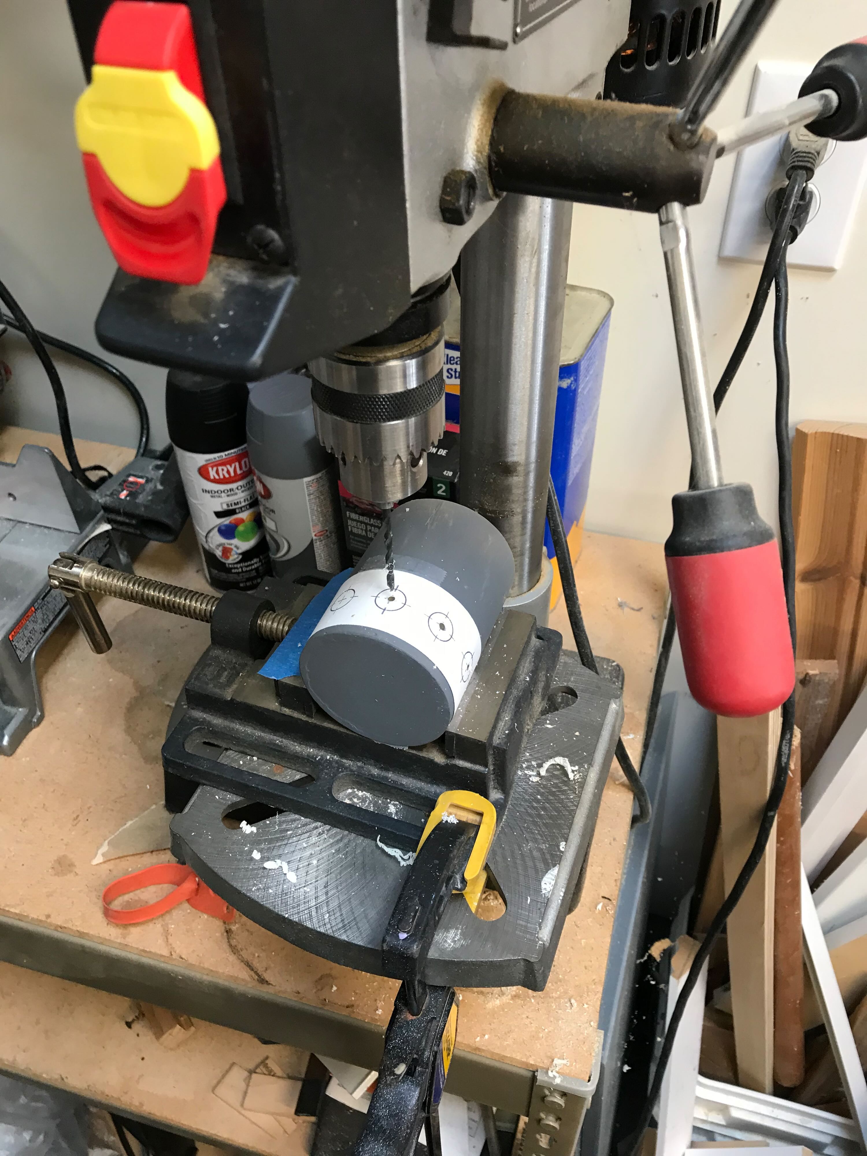
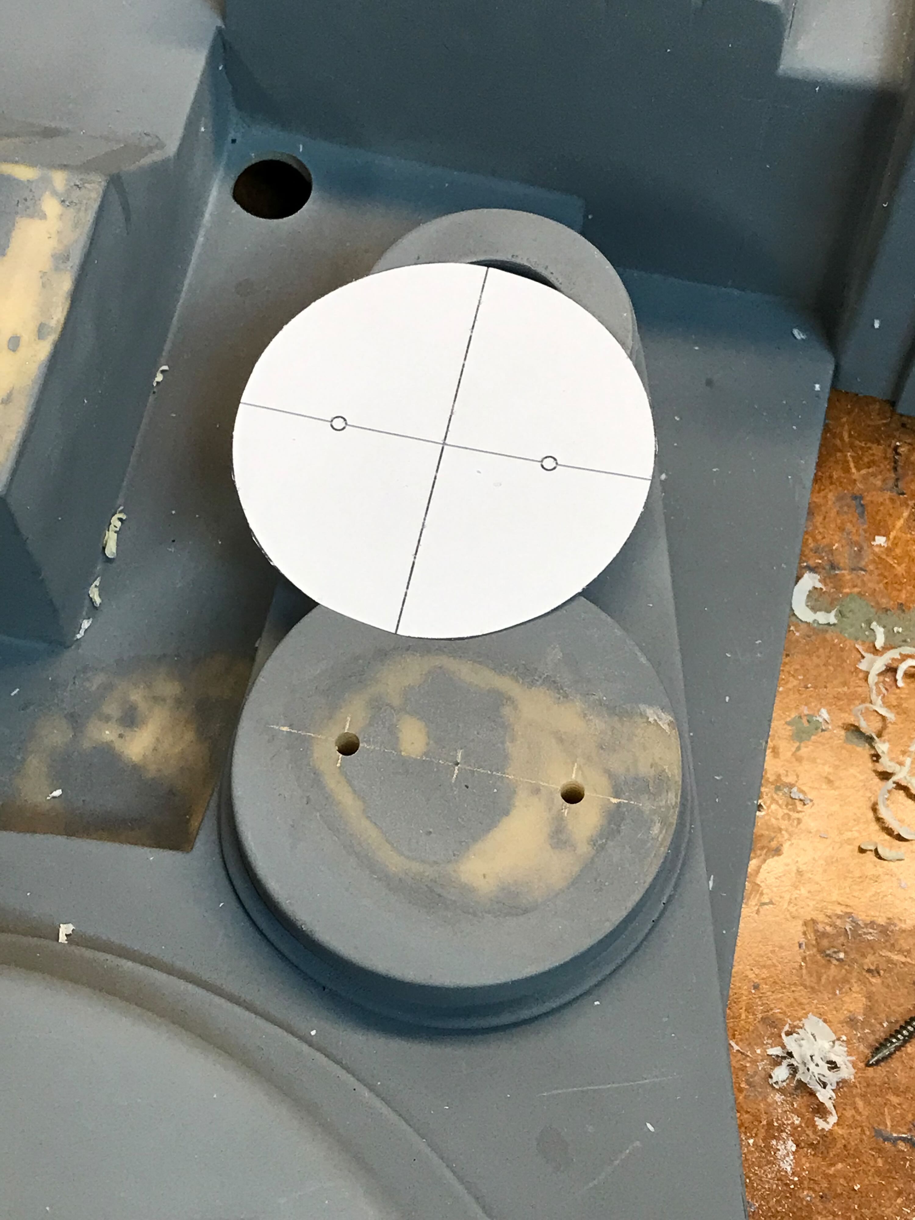
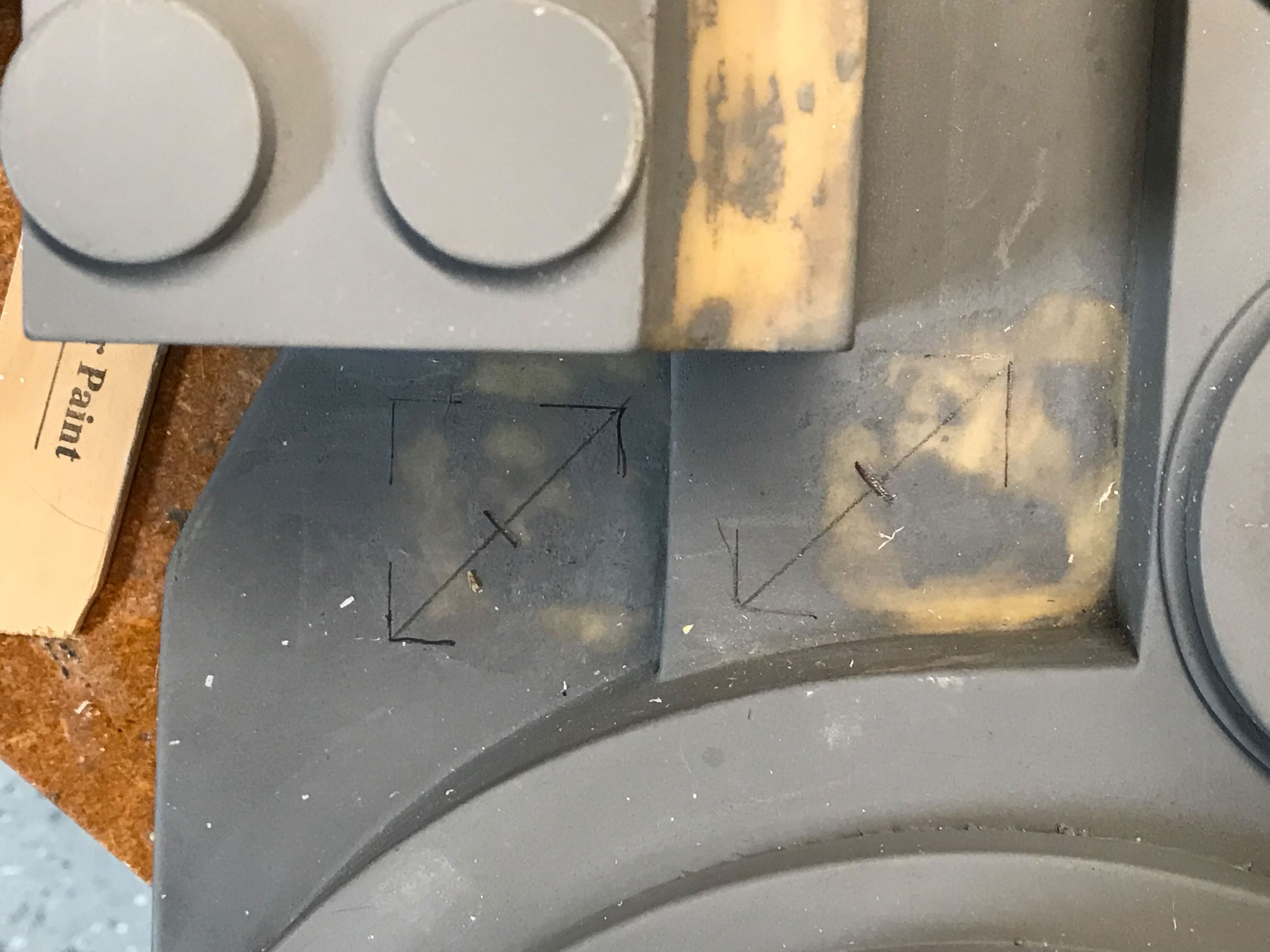
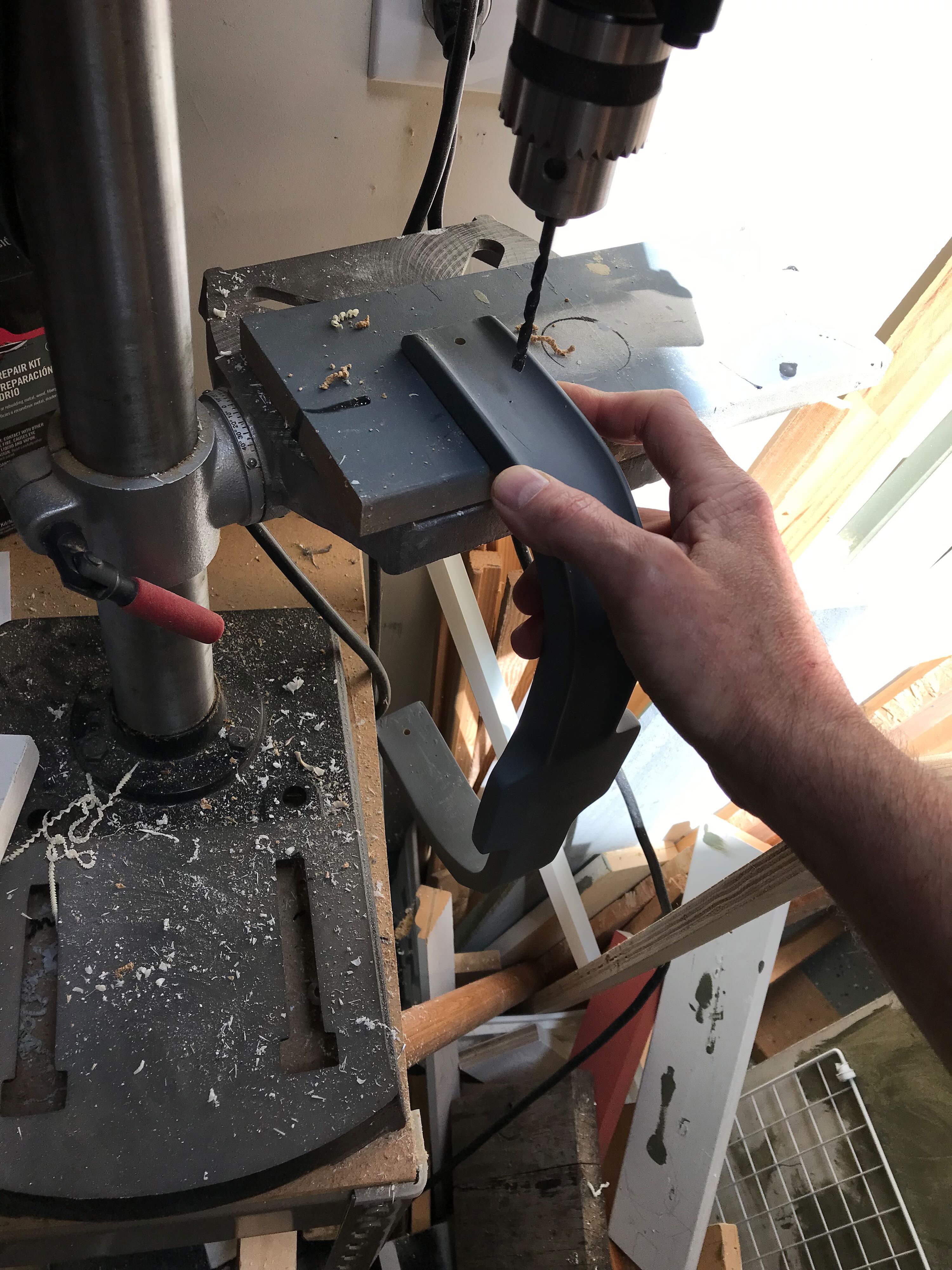
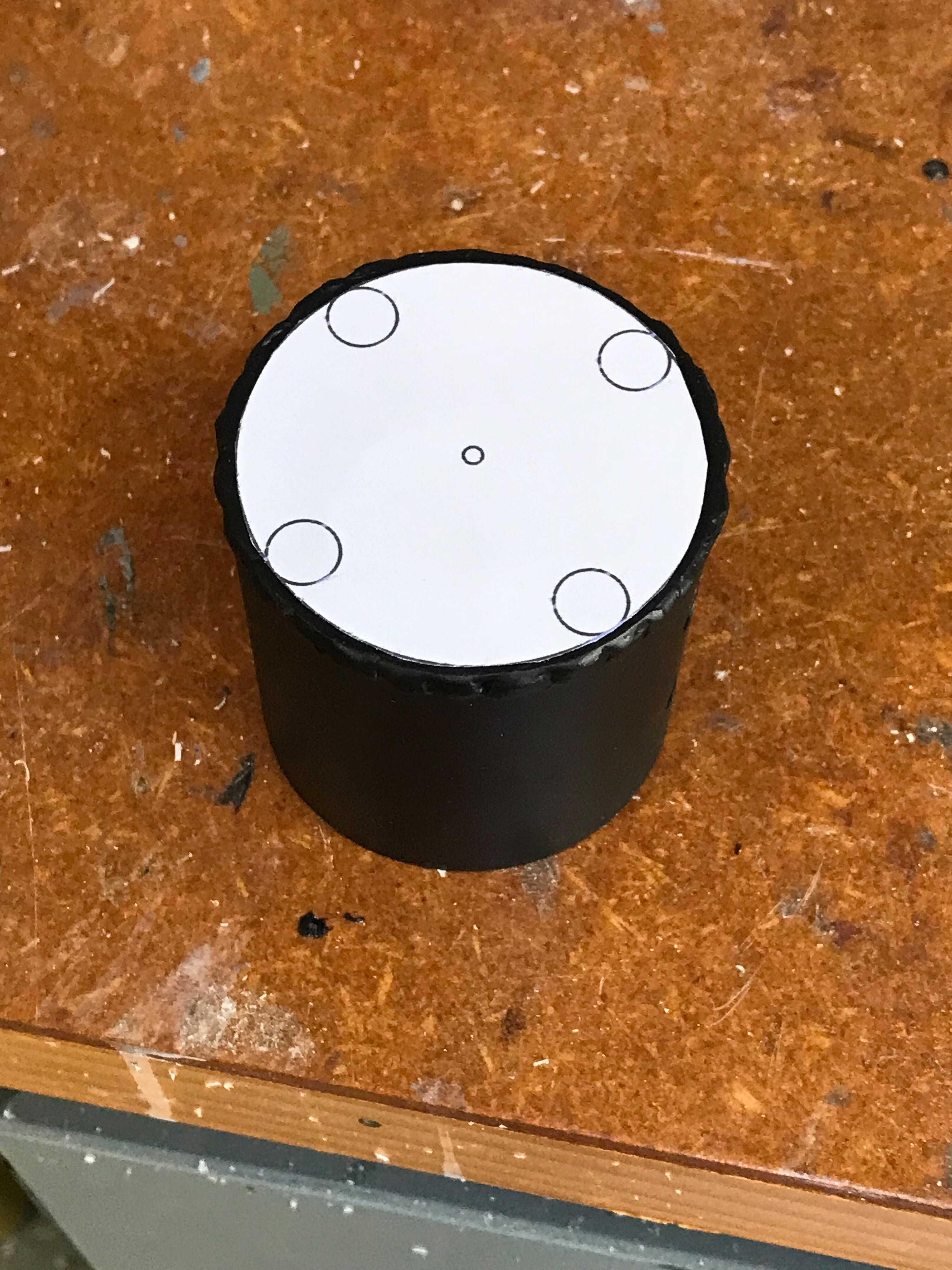
6/22/22 I made a simple template in Adobe Illustrator to mark and drill the holes for the pack Clippard. I routed out the resin inside to accommodate the nuts.
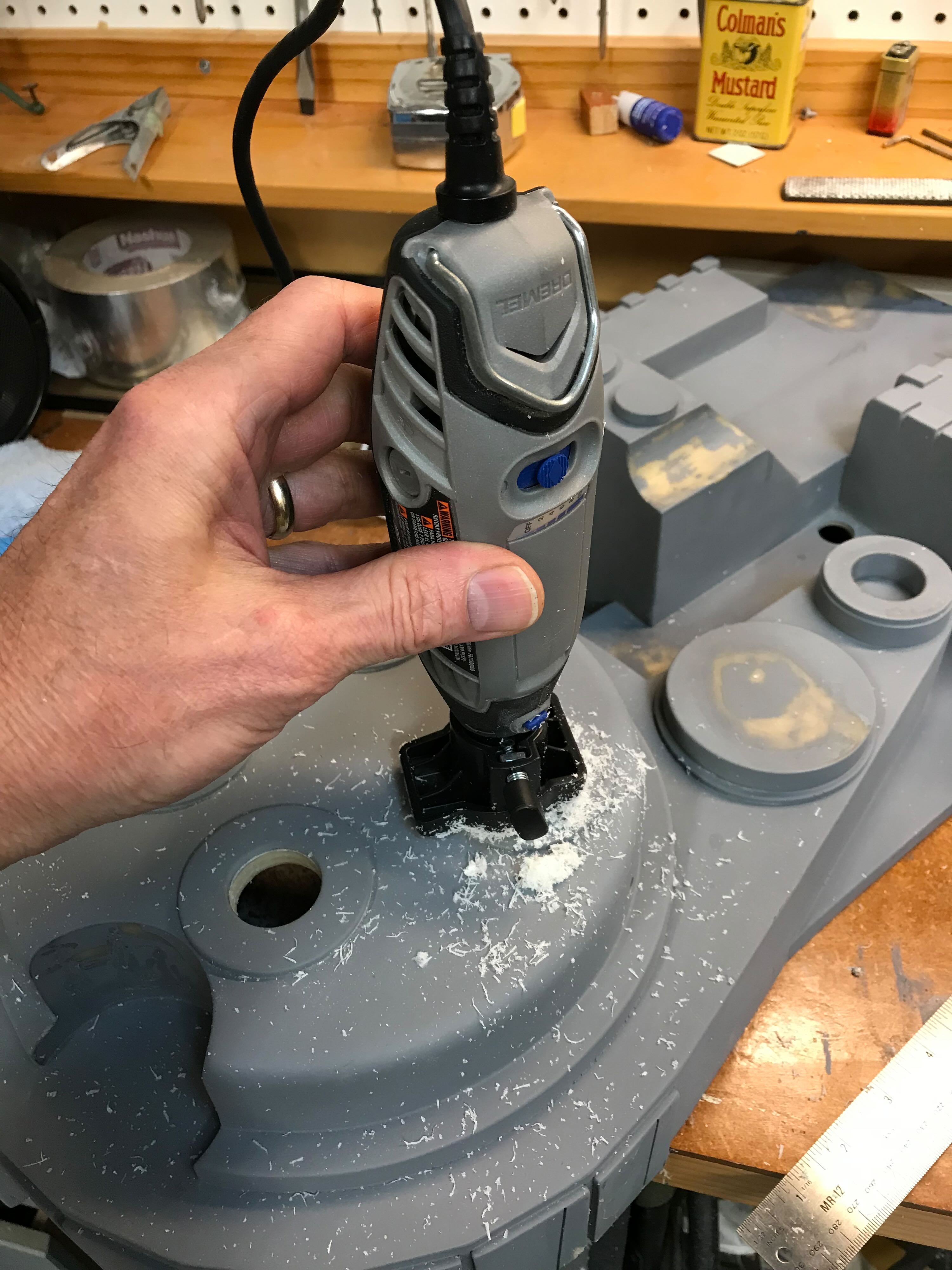
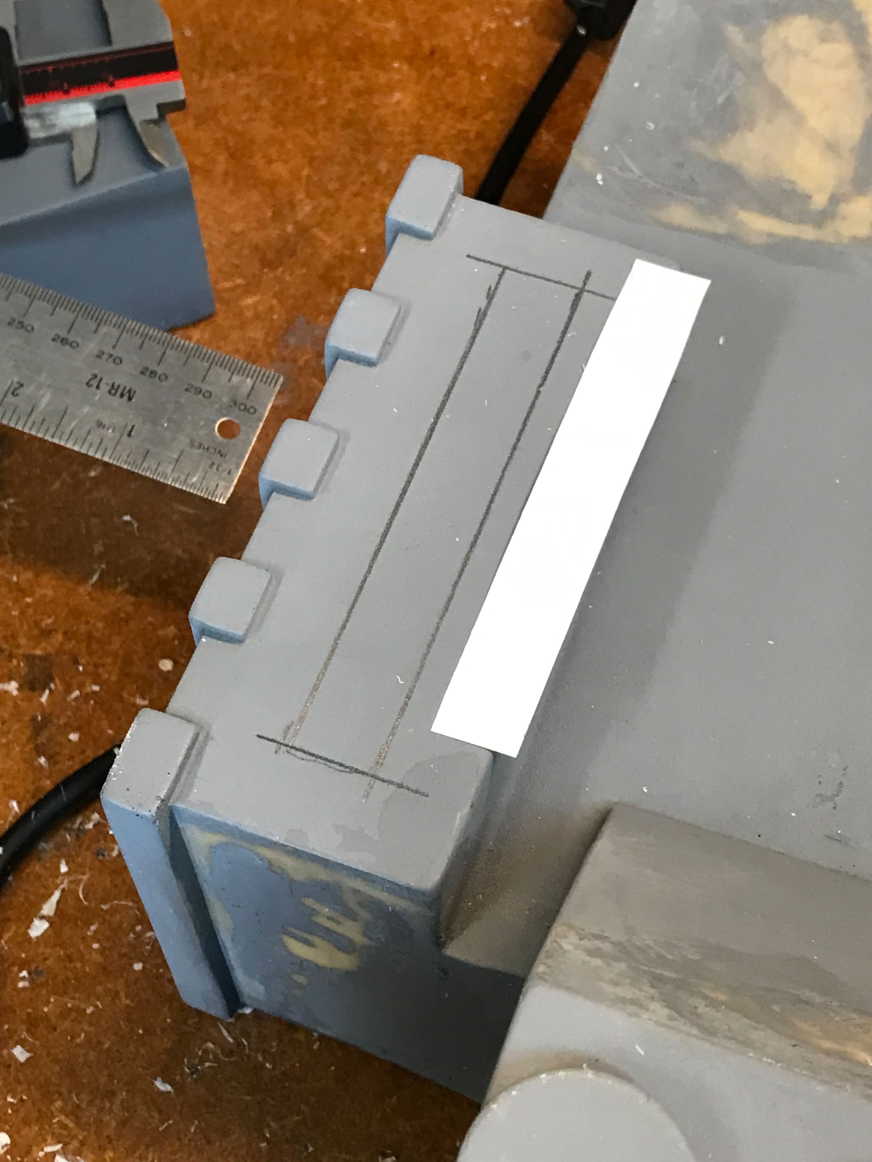
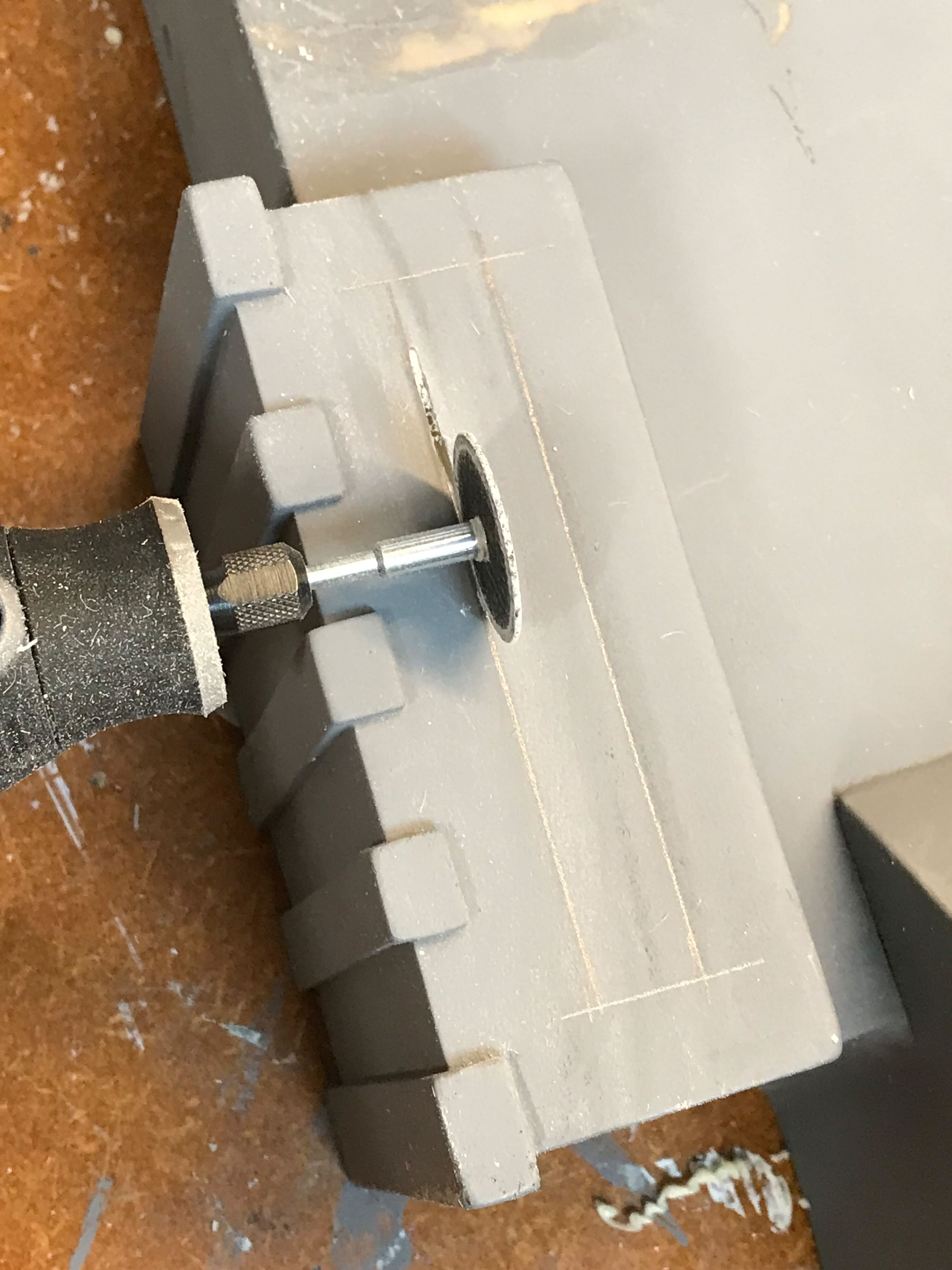
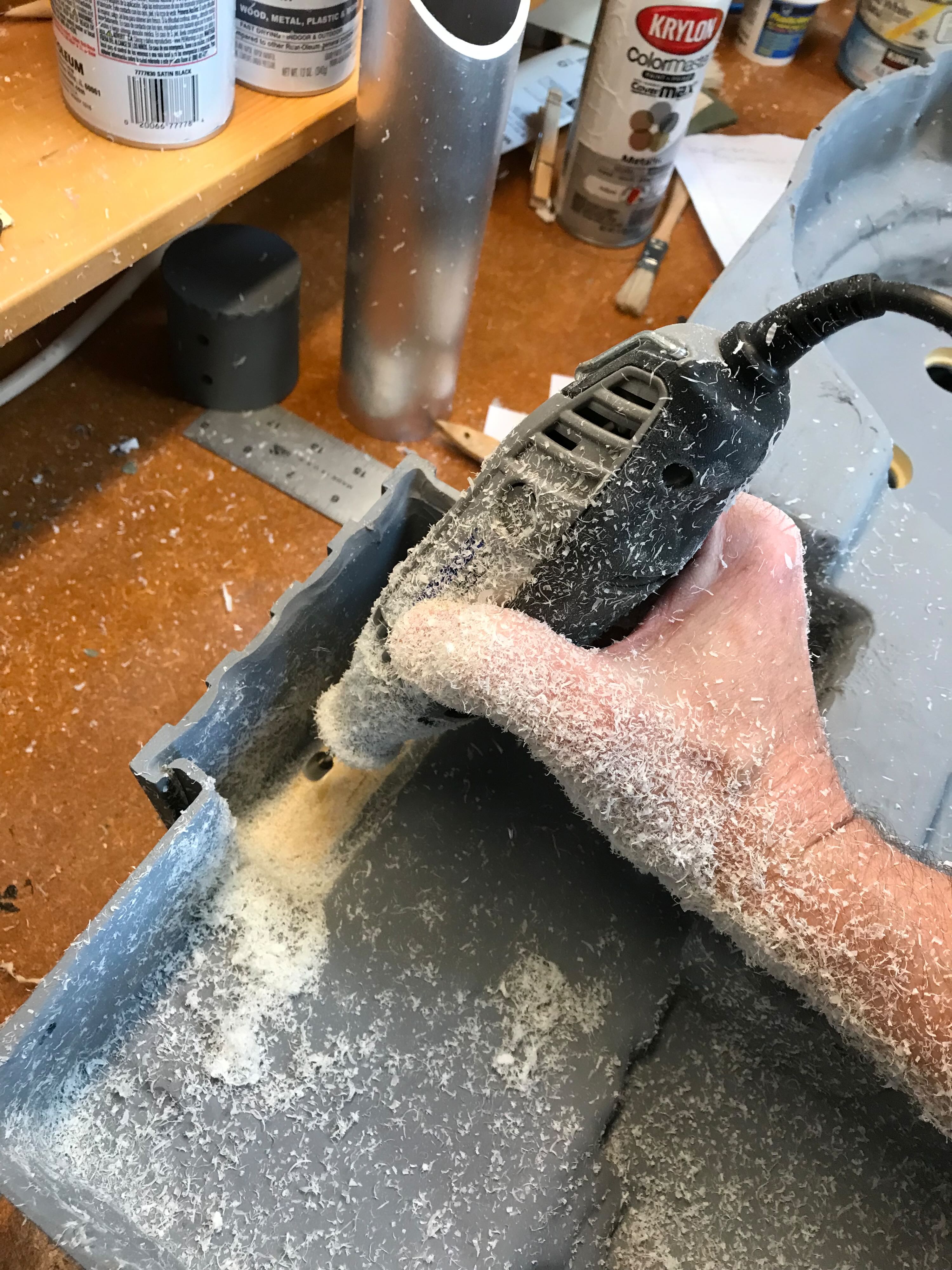
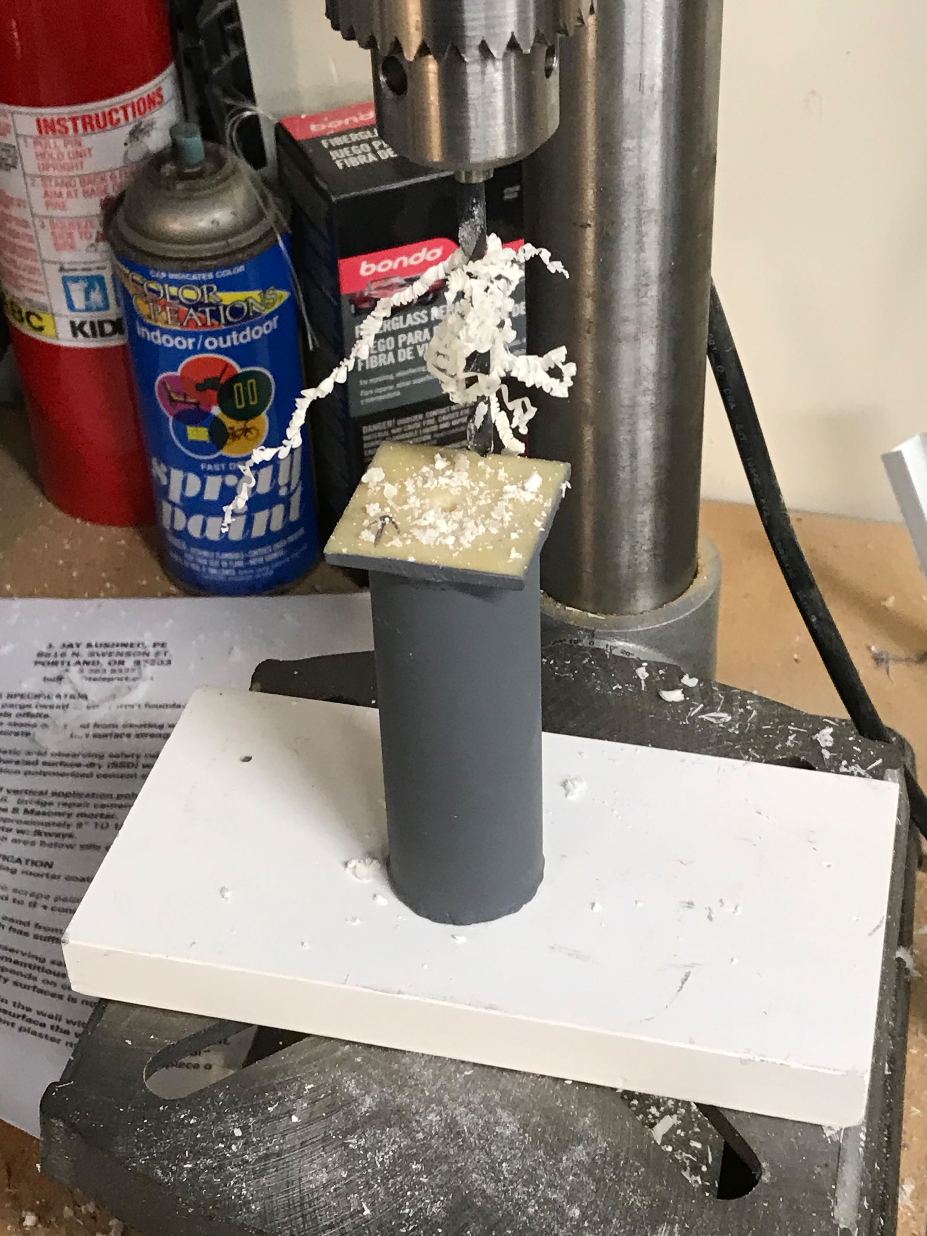
I traced out the shape of the power cell lights window and used a cutting wheel to open it up. The resin was too deep for the wheel to penetrate, so I used a carving bit to thin out that area. A LOT of resin shavings. I wore a respirator.
I wanted to even out more of the area inside around the cyclotron holes, so I used the wheel cutter and my guide attachment to extend a clean edge around the holes. This created shavings AND smoke. Using the carving bit I routed out the resin down to those slots I’d cut.
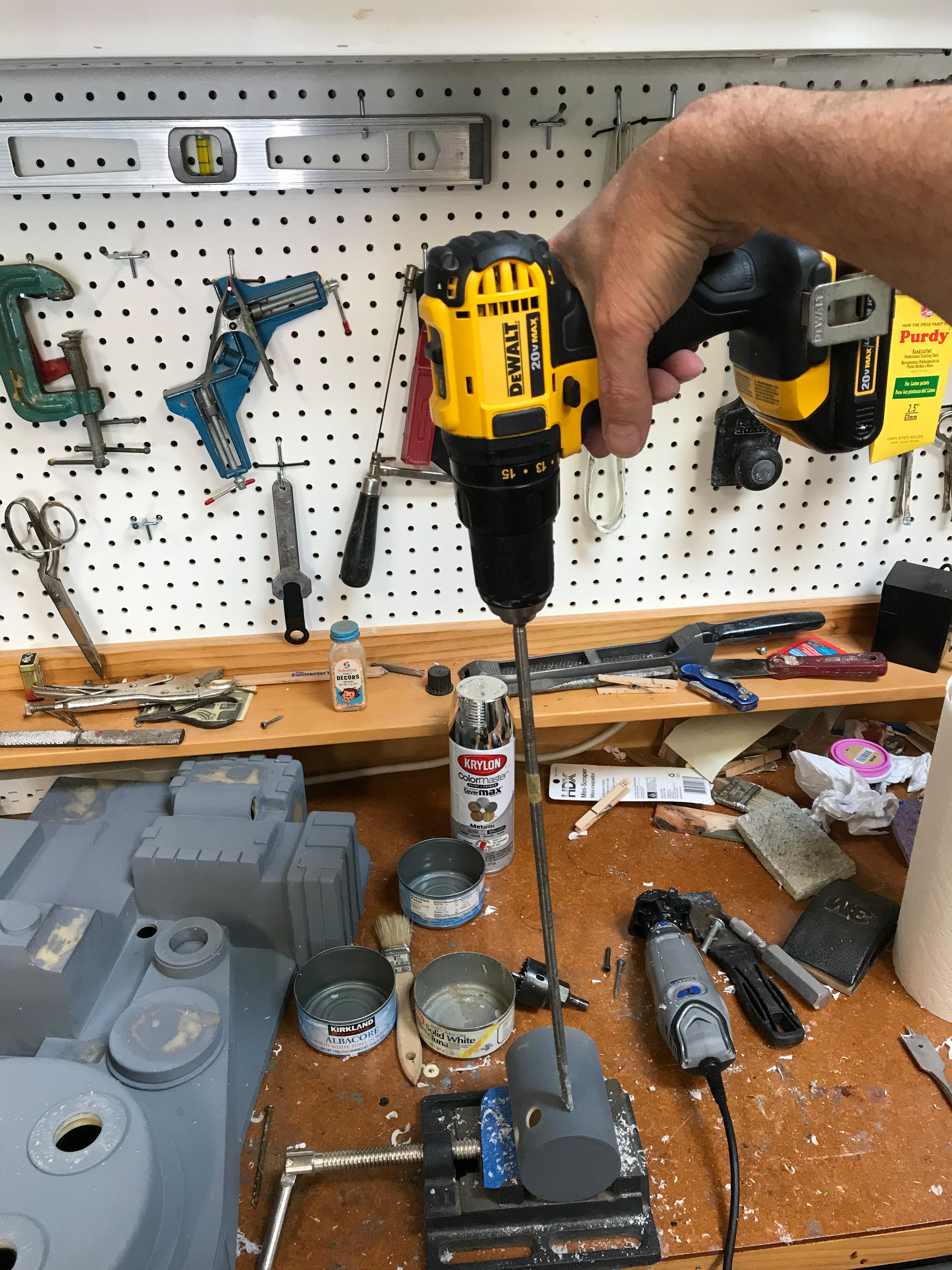
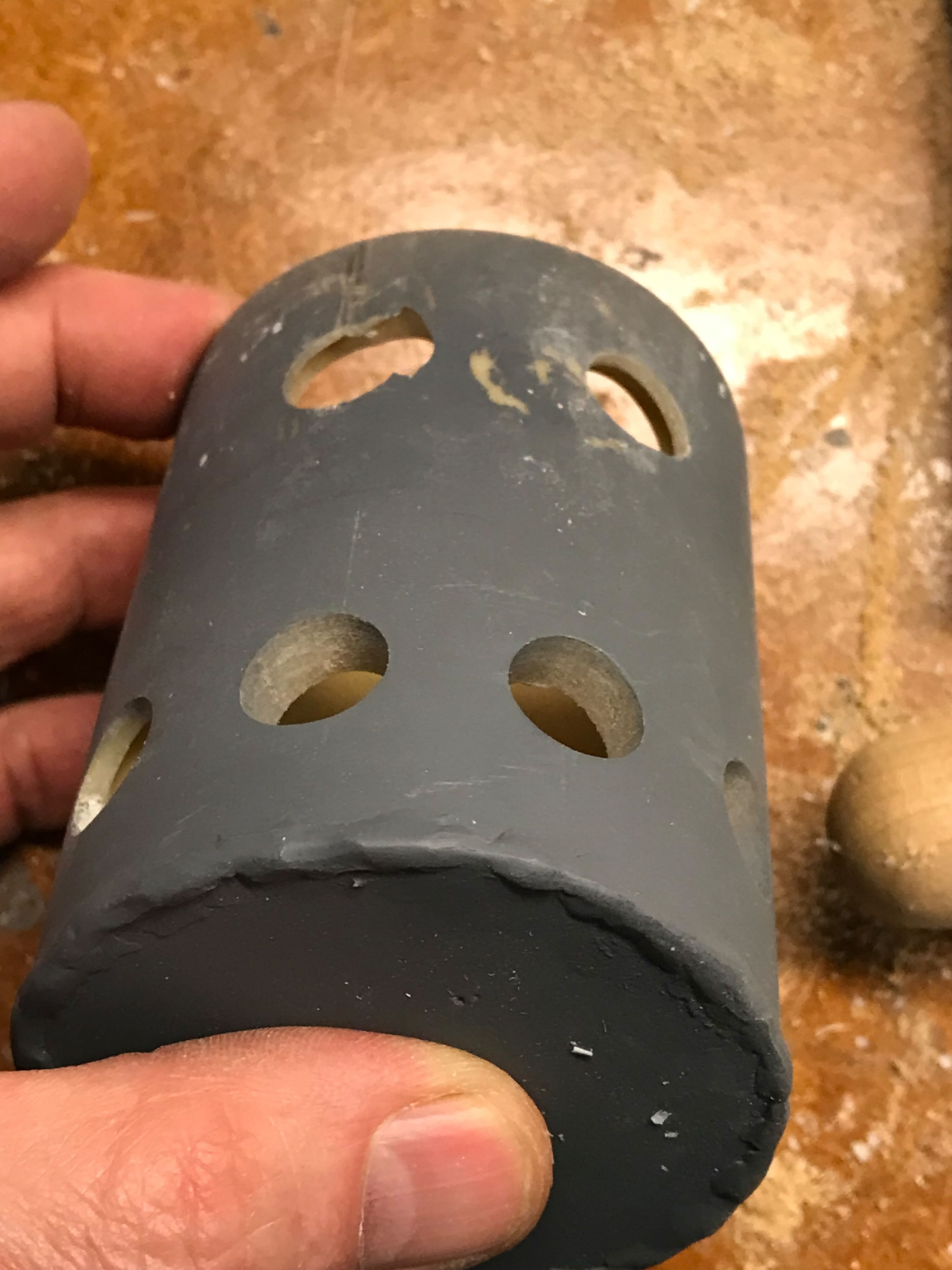
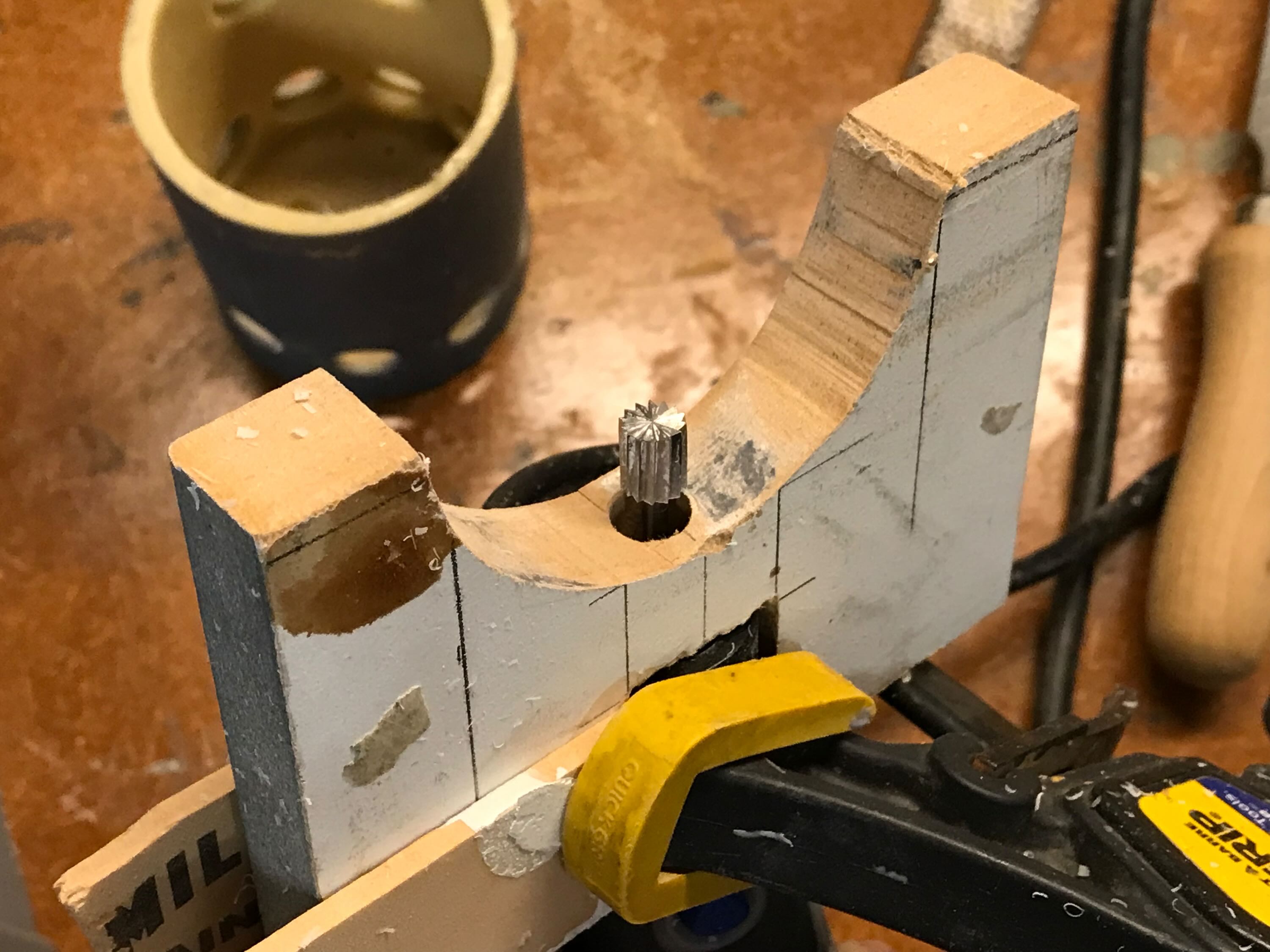
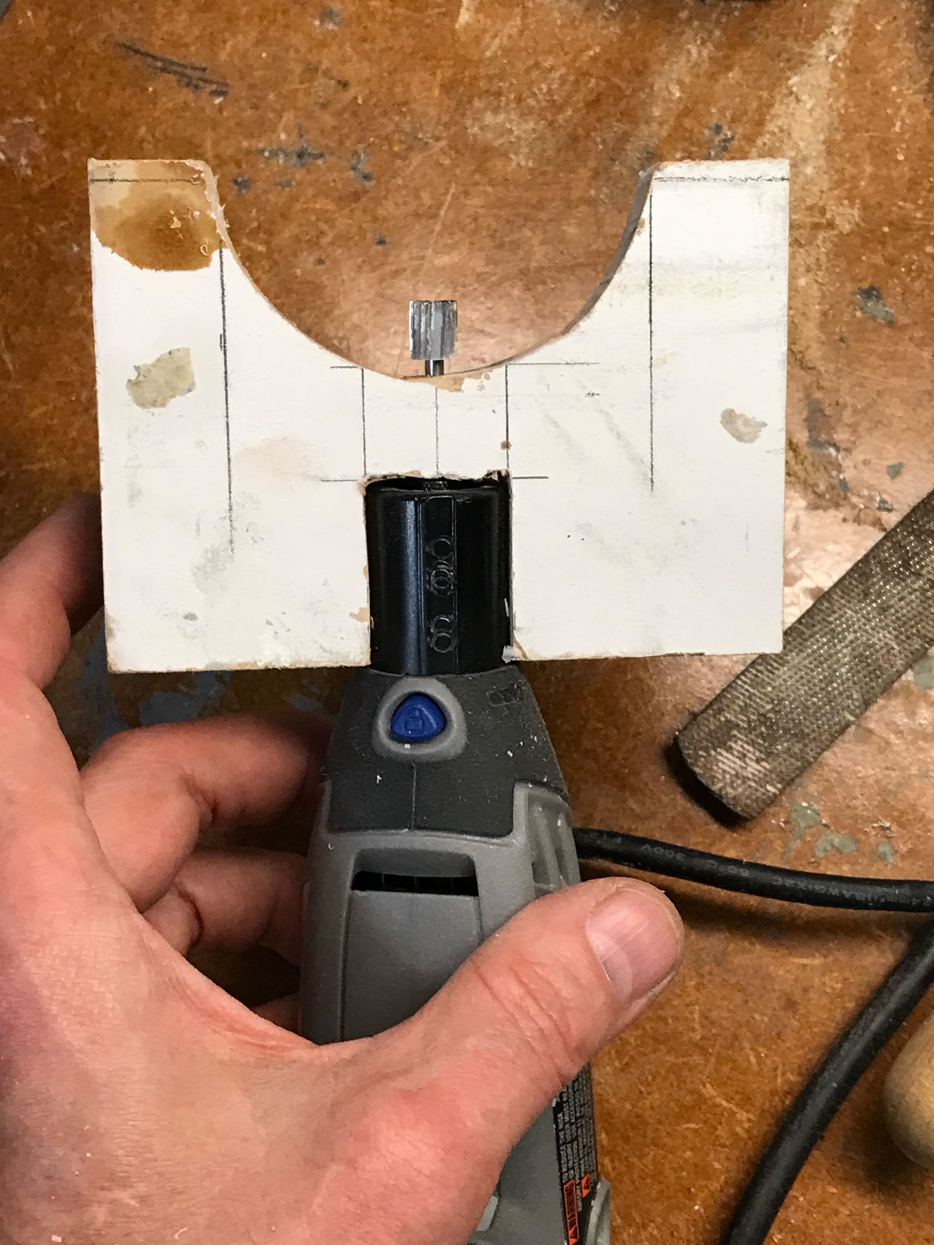
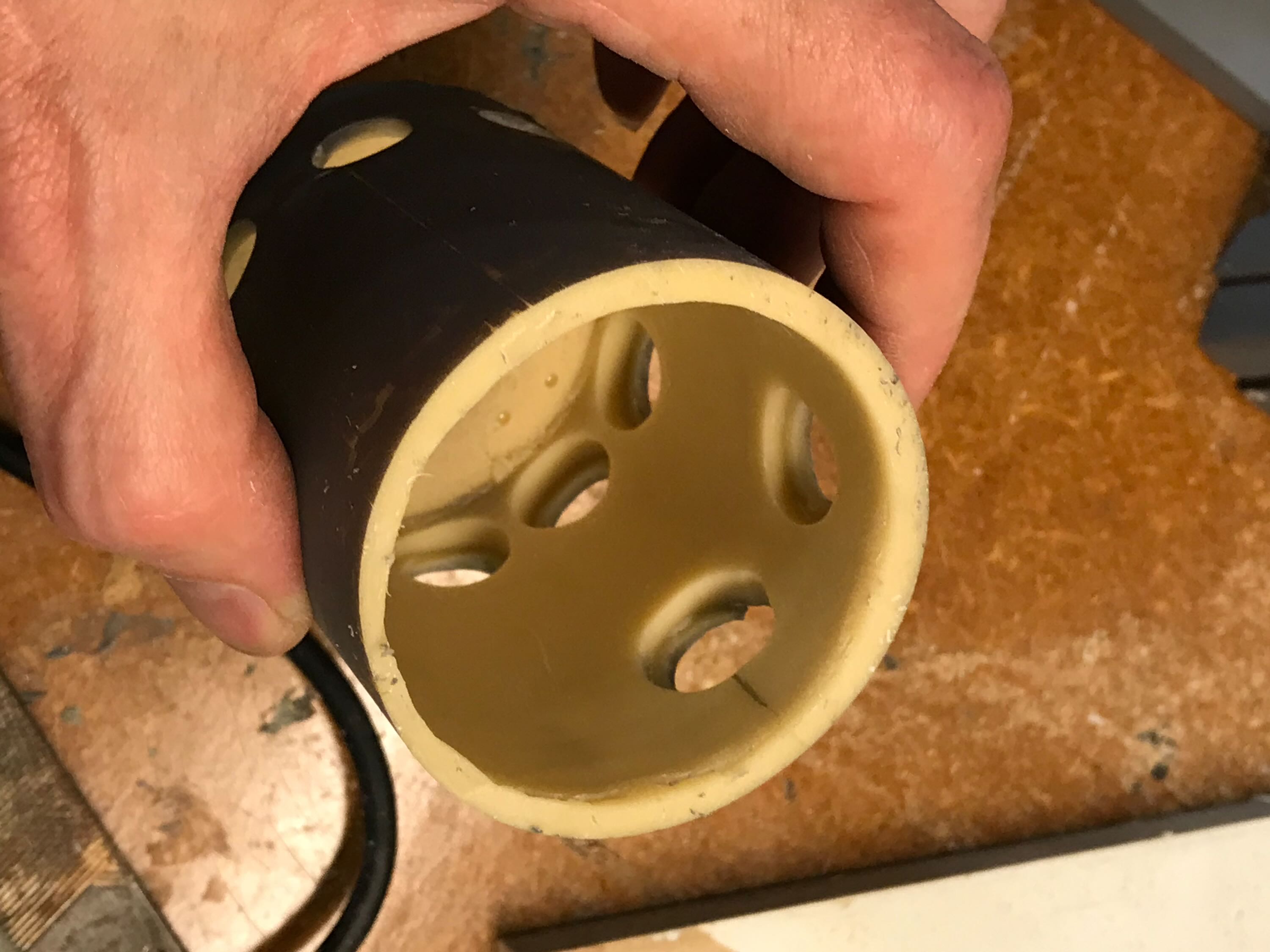
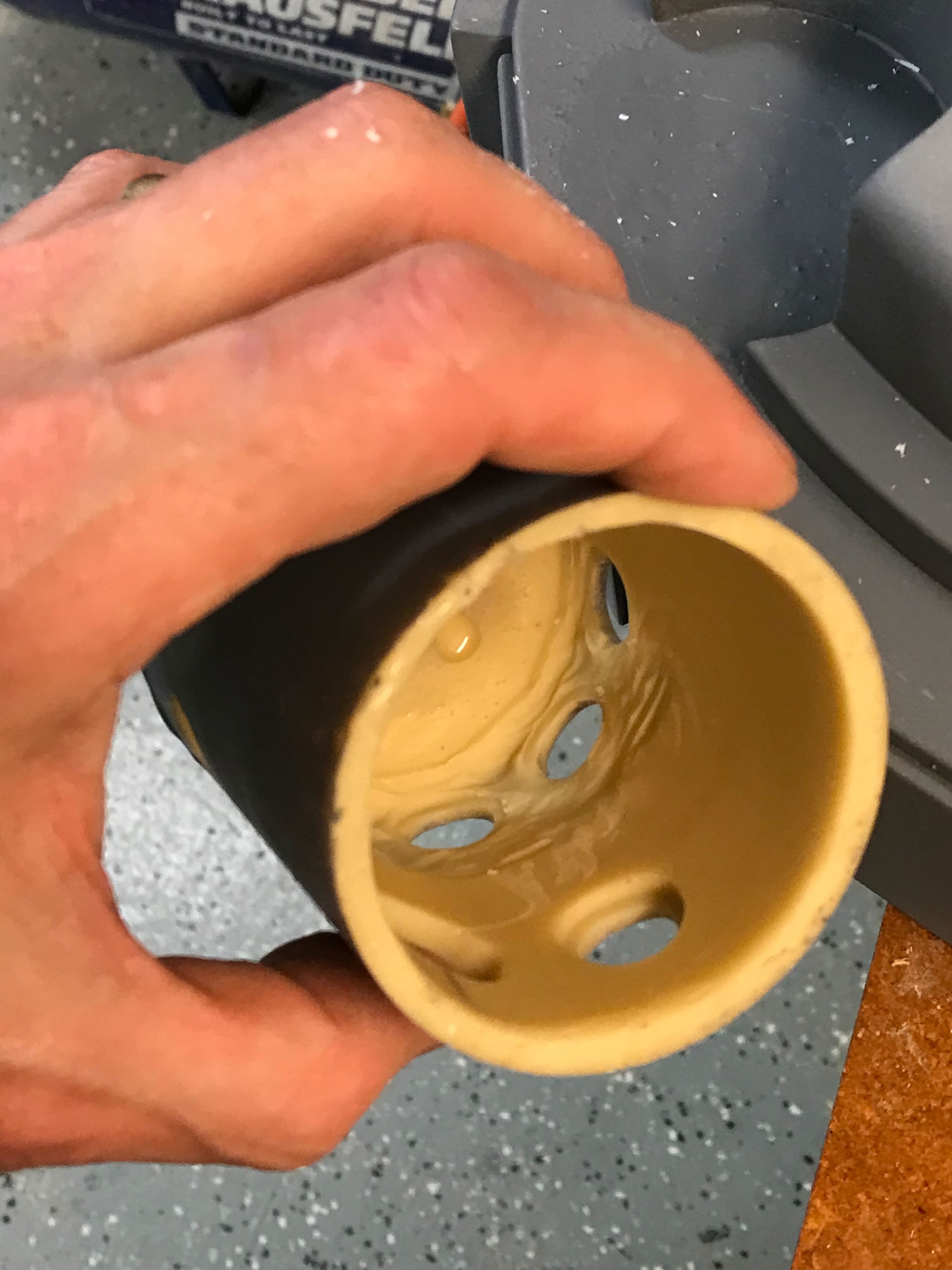
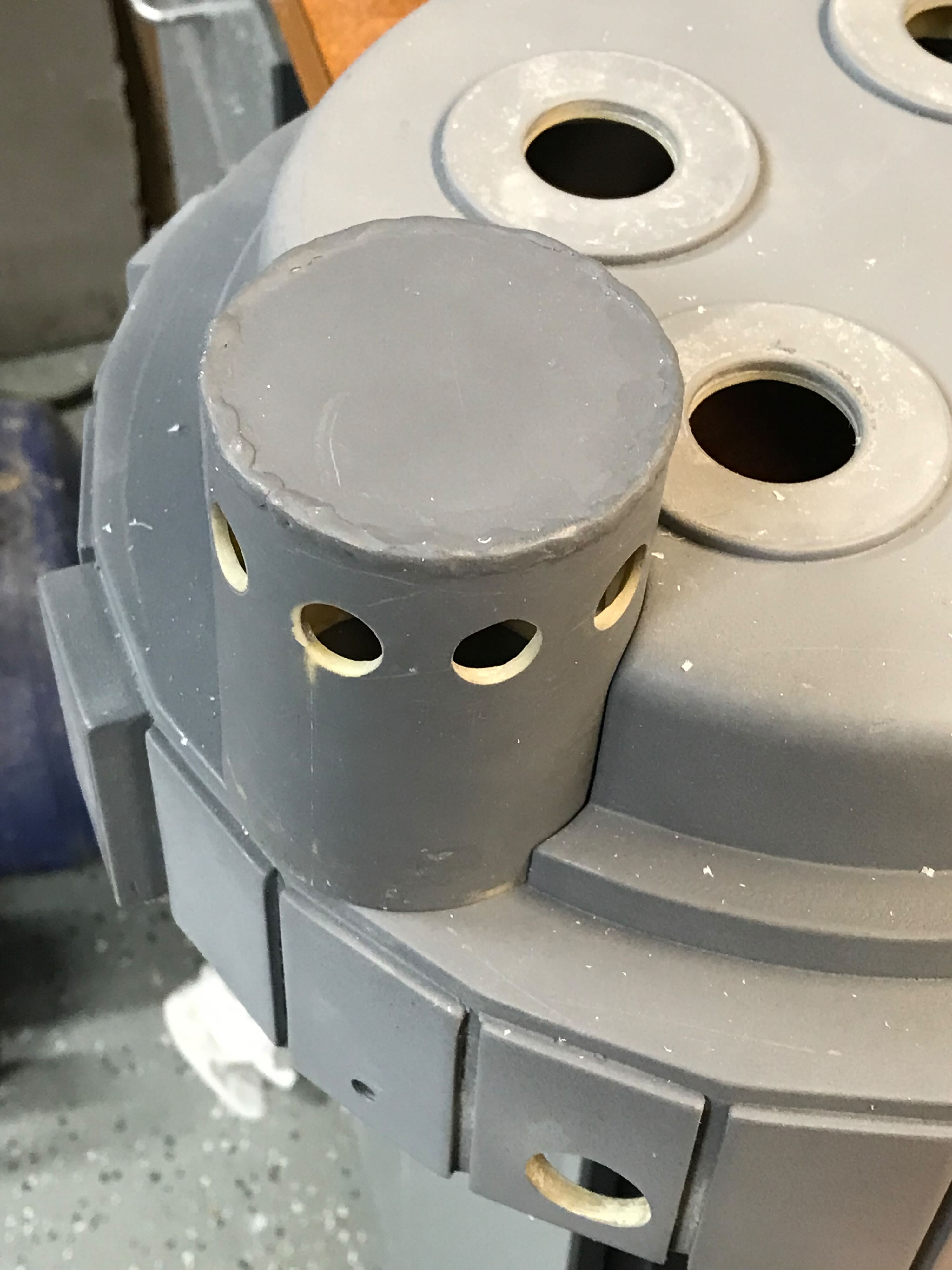
The resin in the N-Filter was very uneven, so the lips of the holes I cut earlier ranged from 3/8" thick to 1/8" thick. I initially tried to use my grinding attachment to guide the carving bit around a test hole (that would be hidden) to create an even lip, but the bit cut outside of my hole. I worked up a jig with a piece of scrap wood that would keep the bit at a tangent to the N-filter, cradling the part and creating a nice even lip around each hole. With those clean lips done I then went in with the carving bit to eat away more resin to get it all down to an acceptable width to accommodate the screen mesh I’d install later.
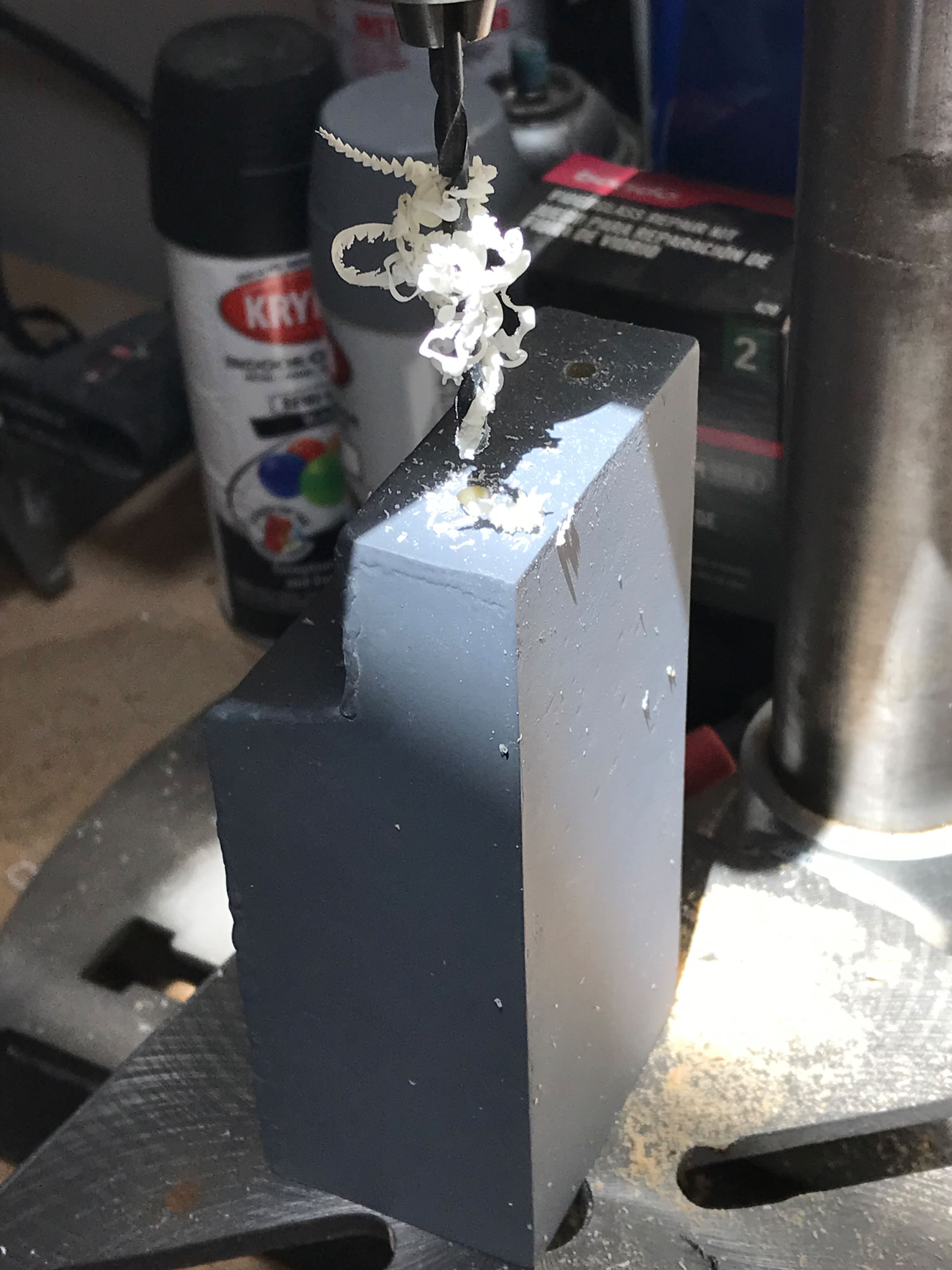
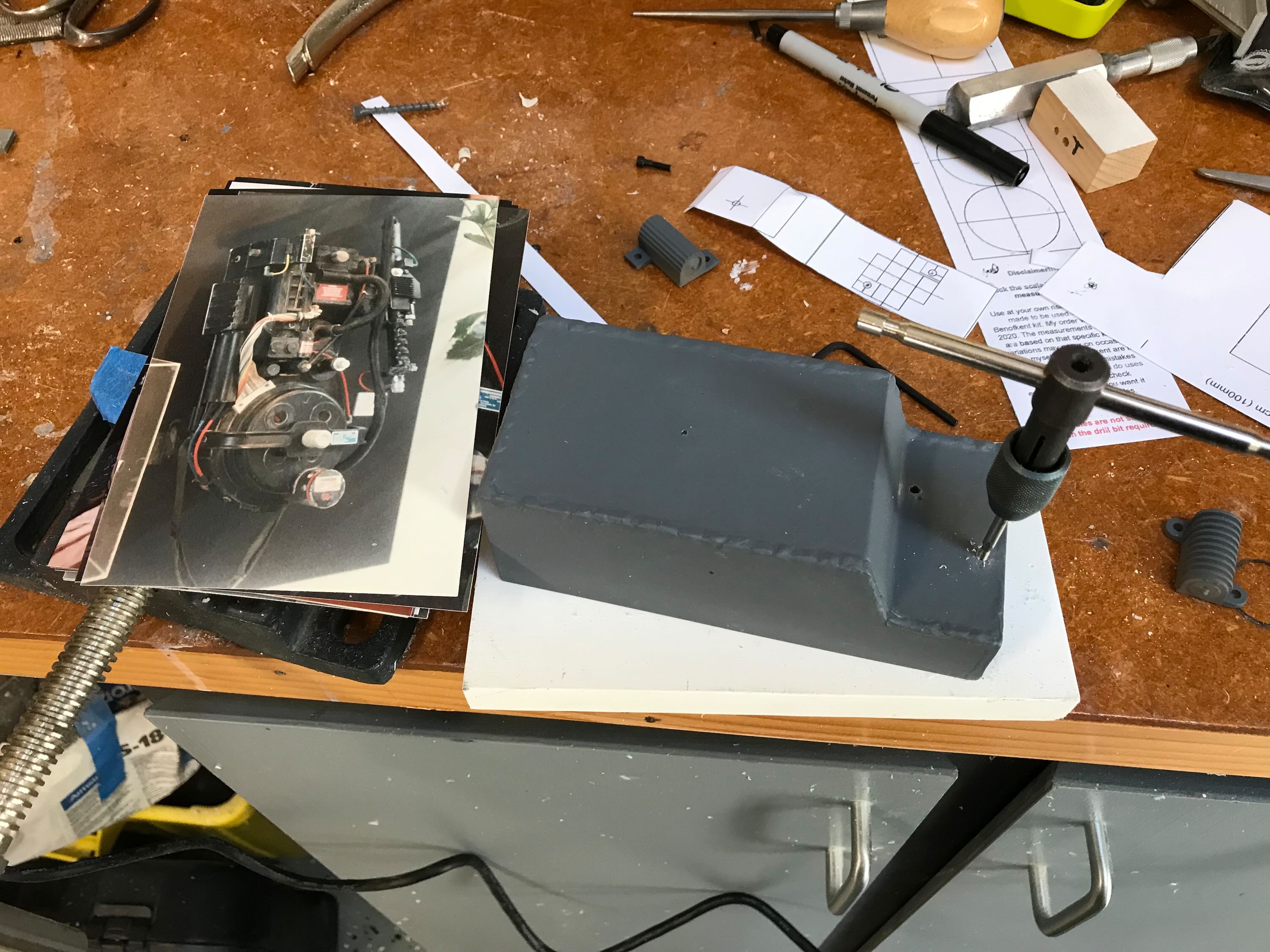
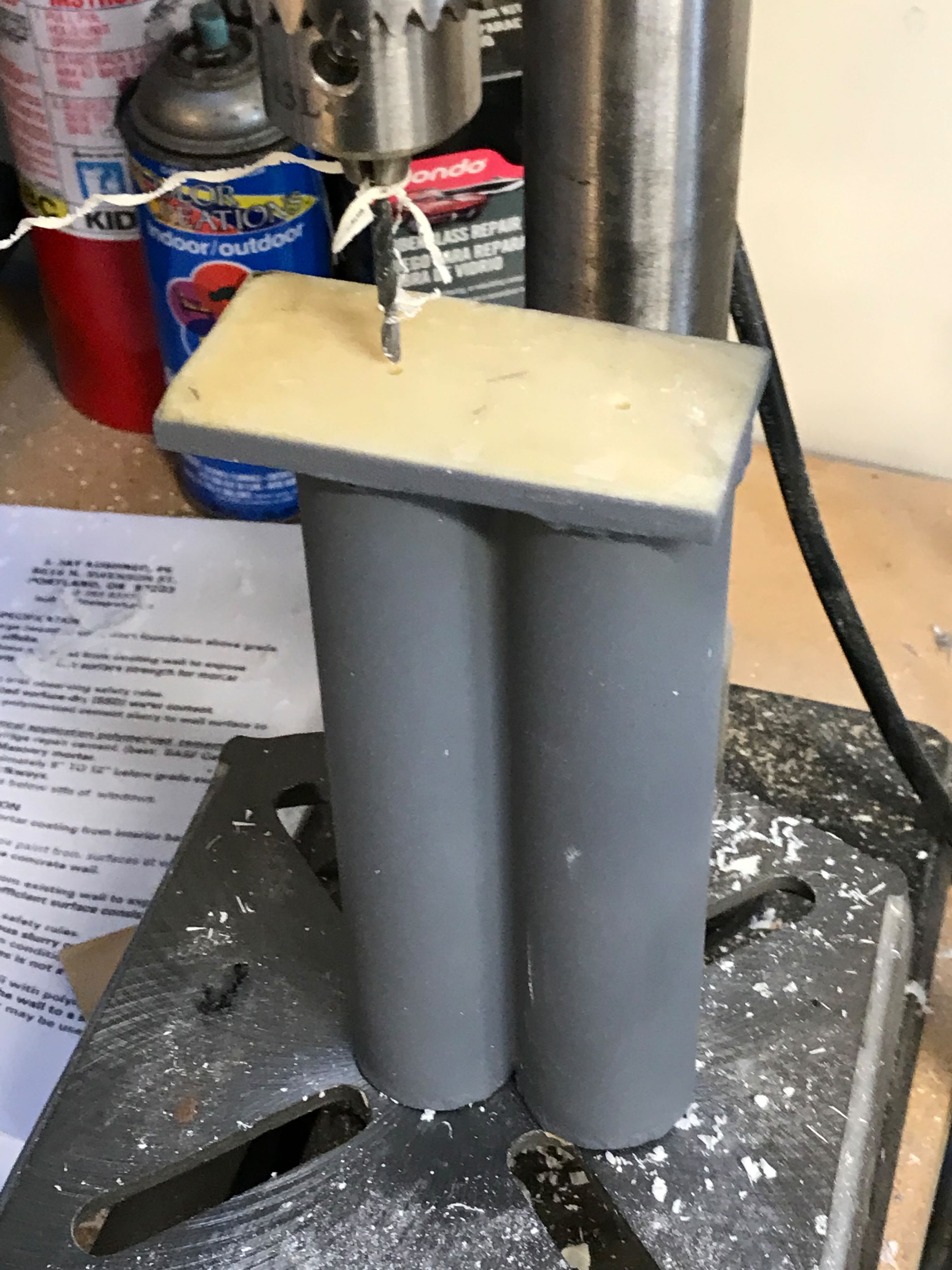
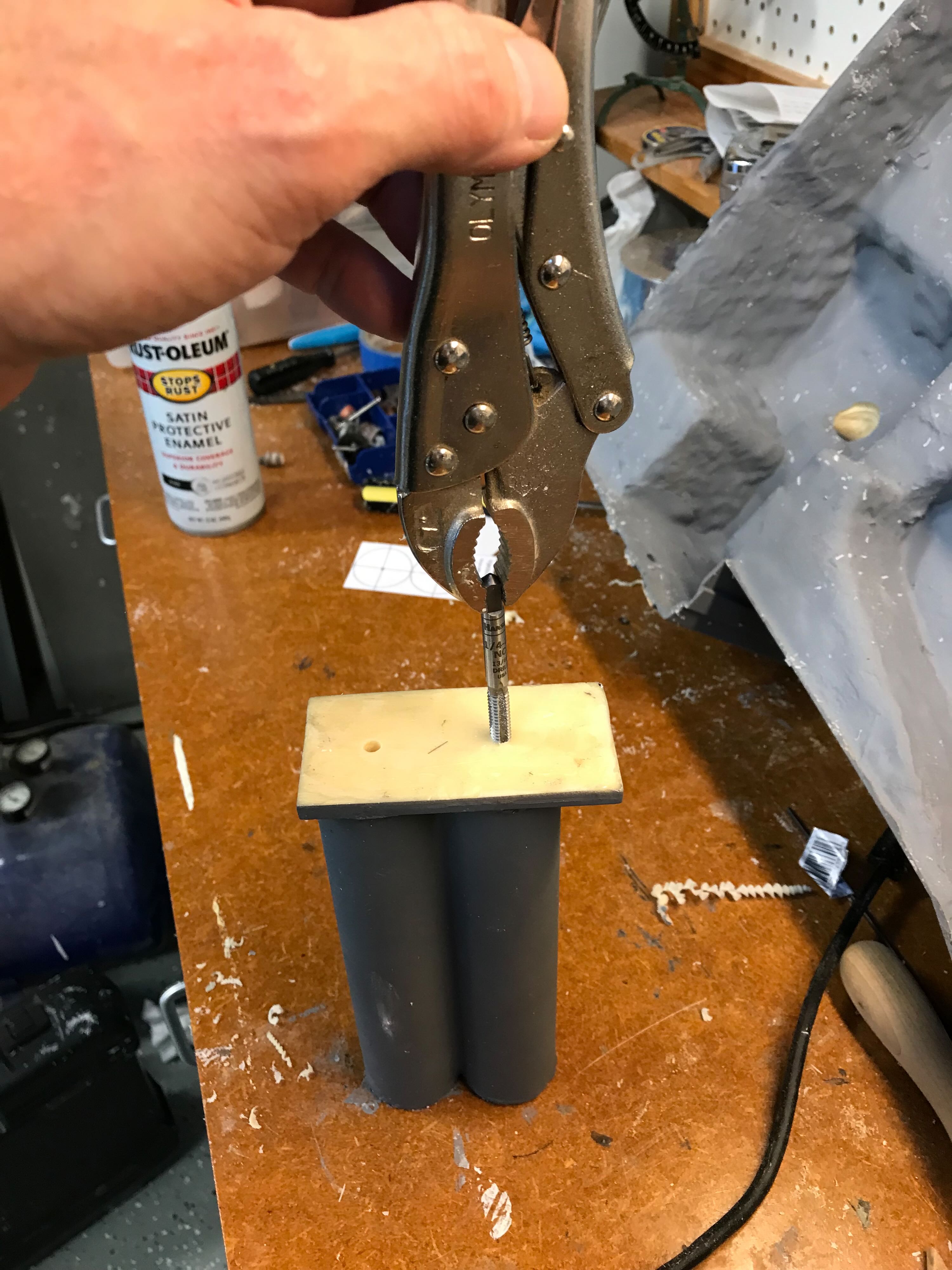
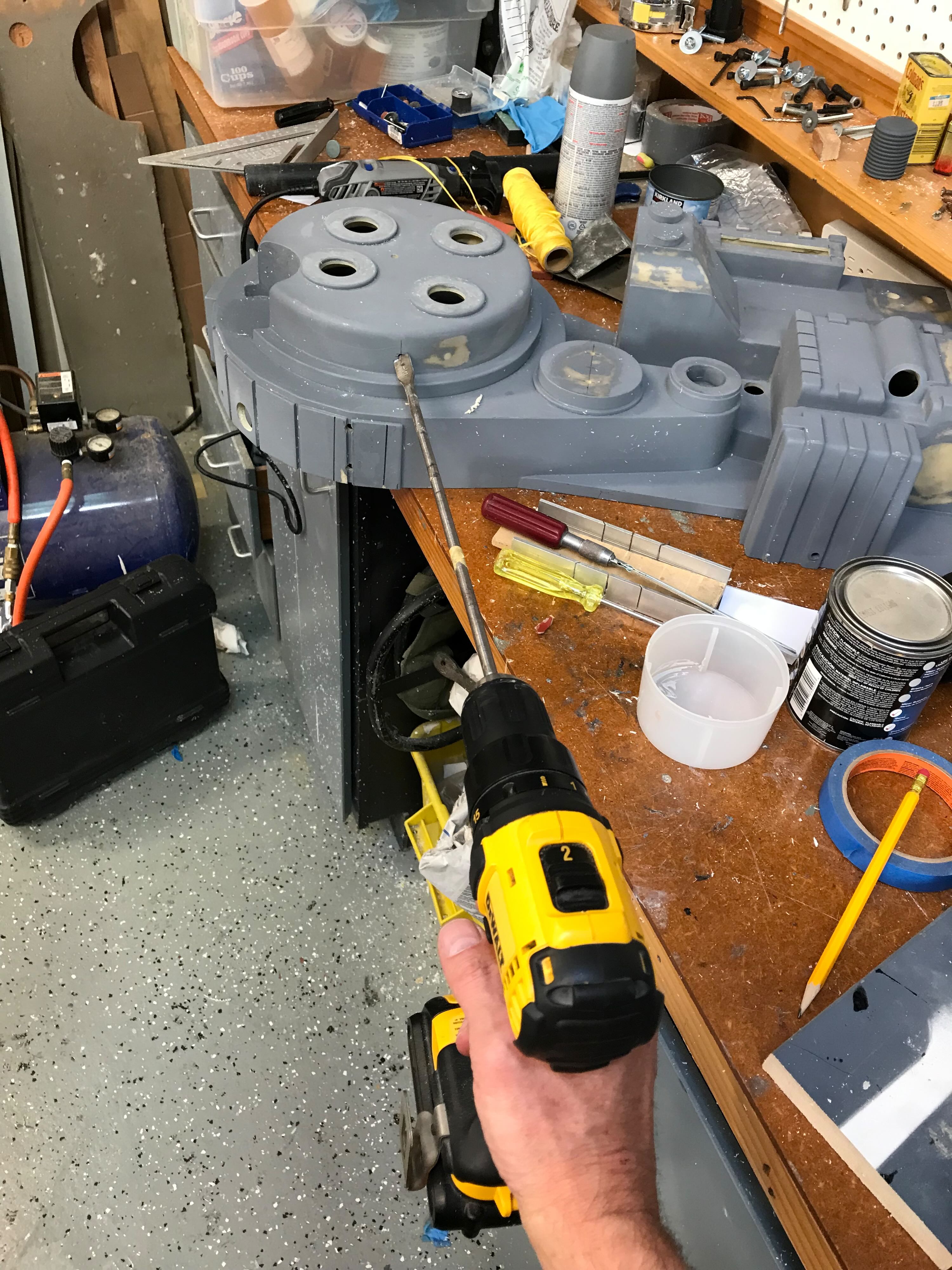
I wanted most every part possible to have a mechanical attachment in addition to epoxy, so I drilled and tapped 1/4" threads to bolt the resin Ion Arm to the shell. I had to route around the holes.
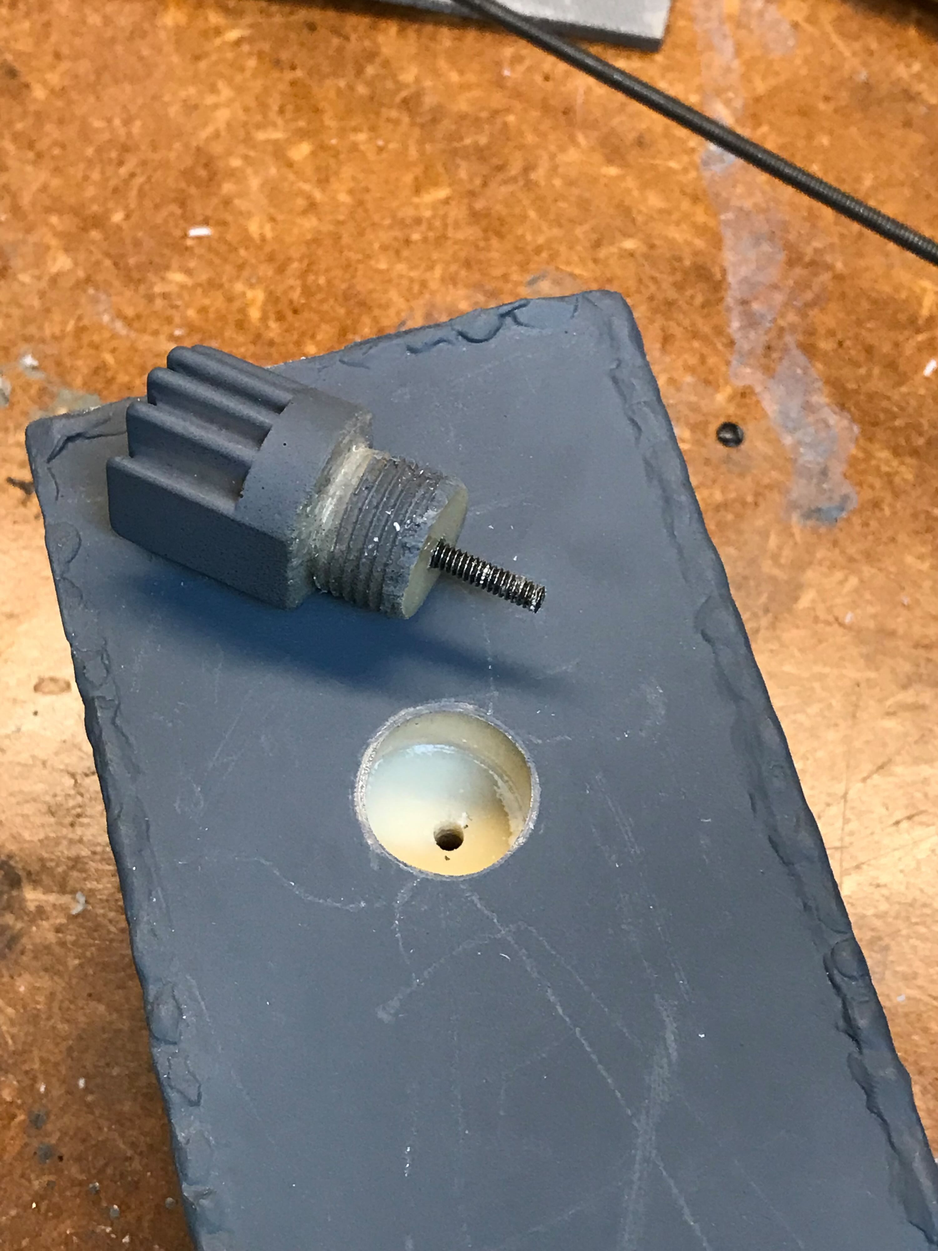
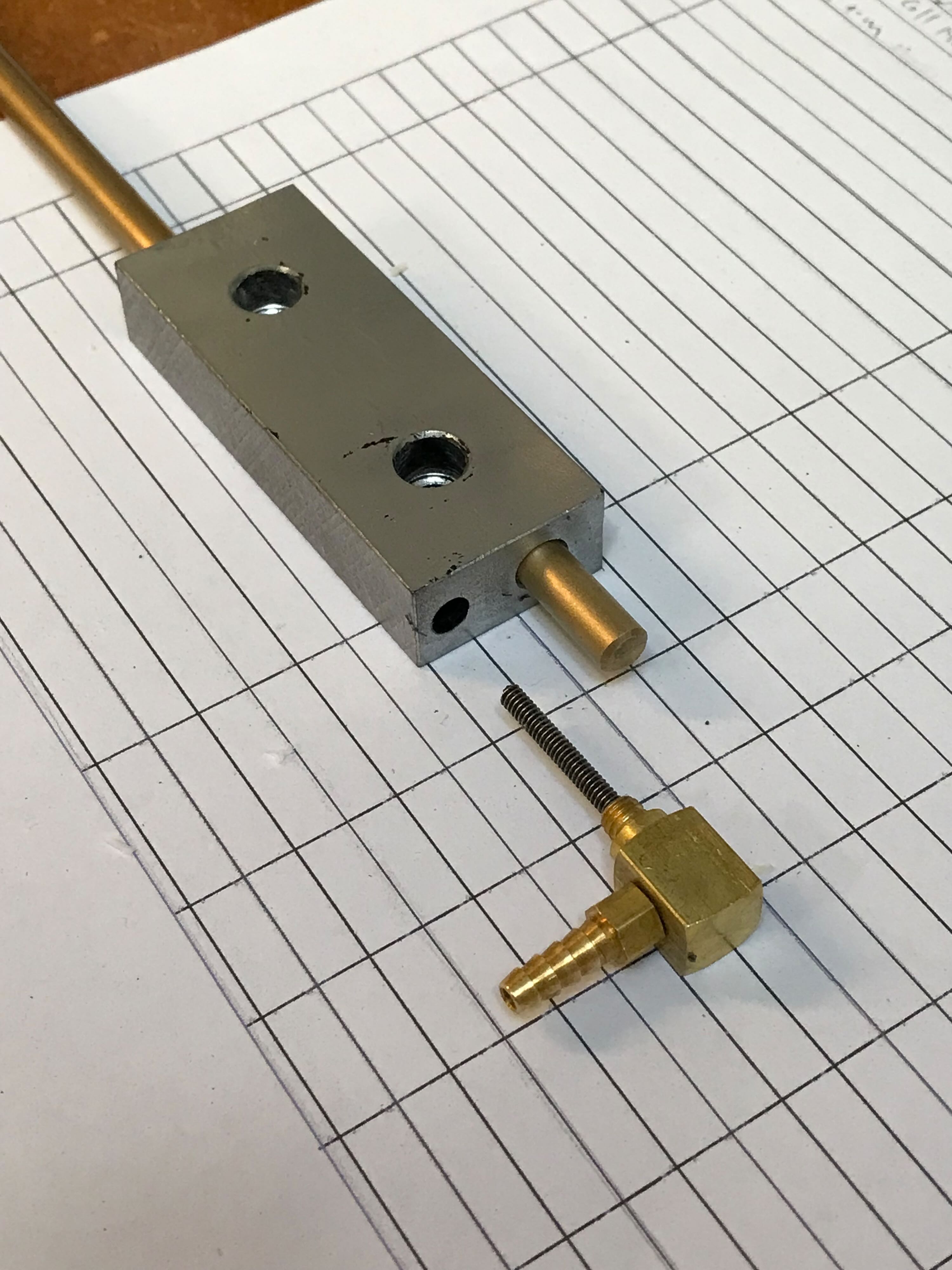
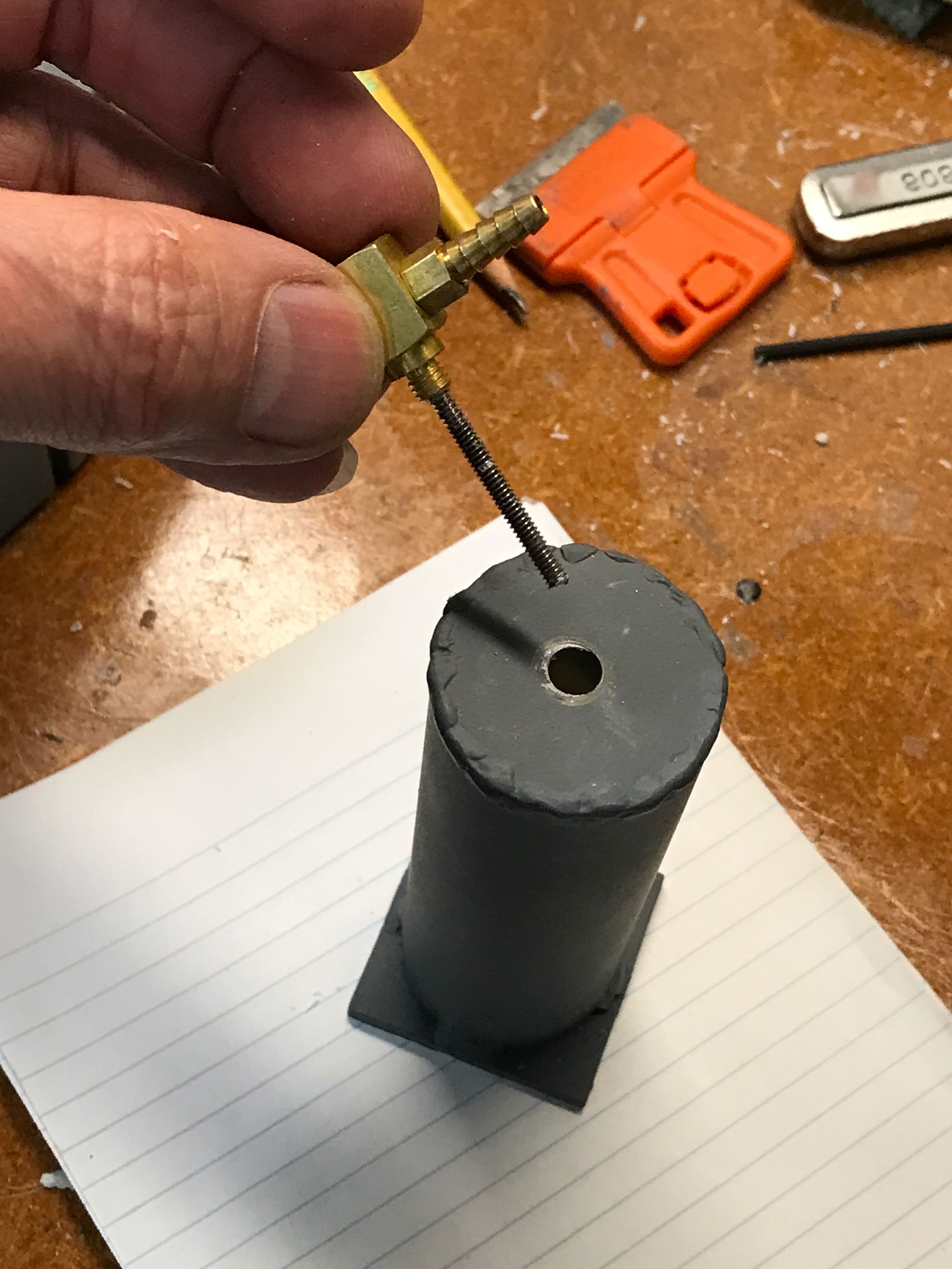
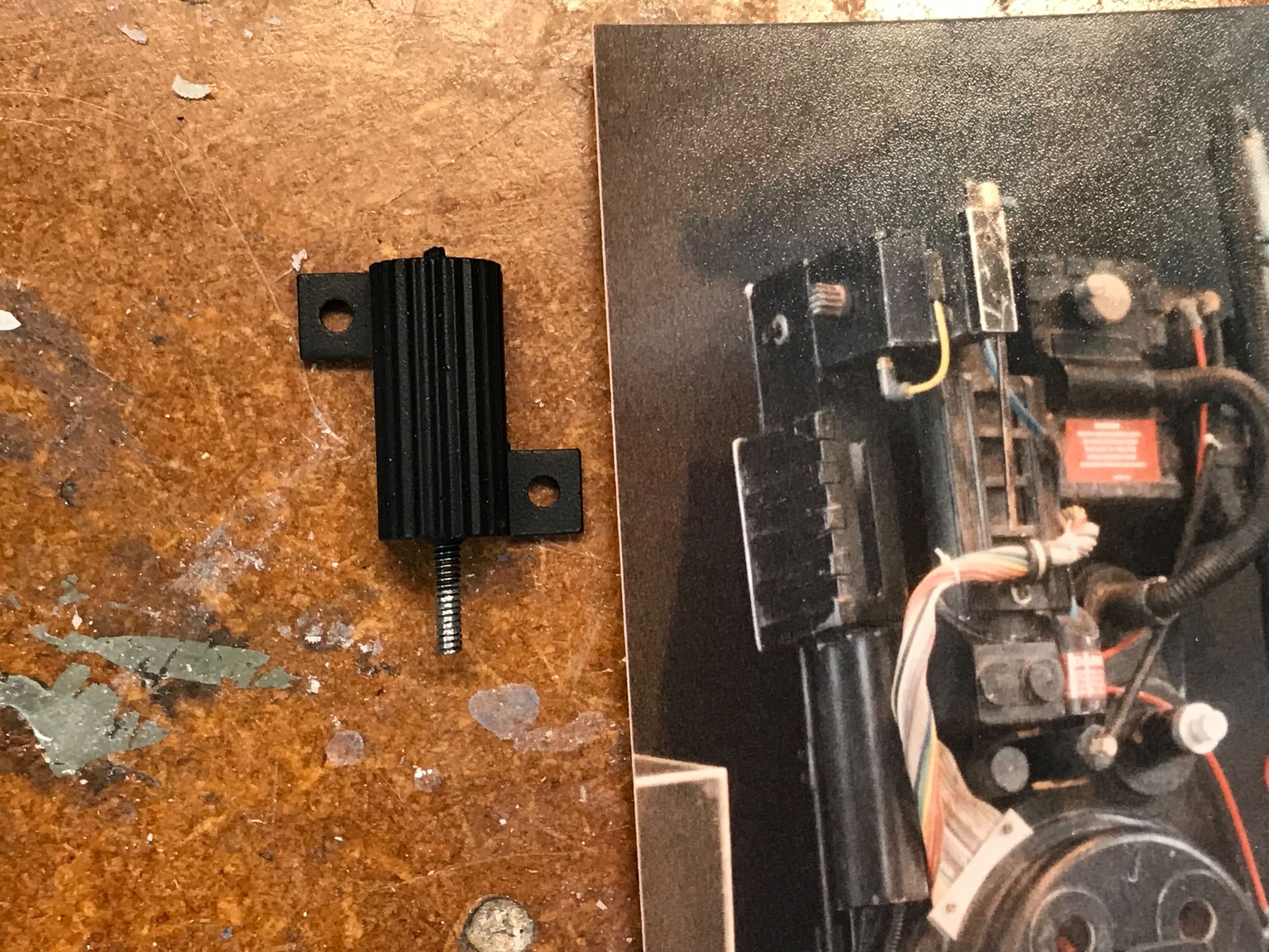
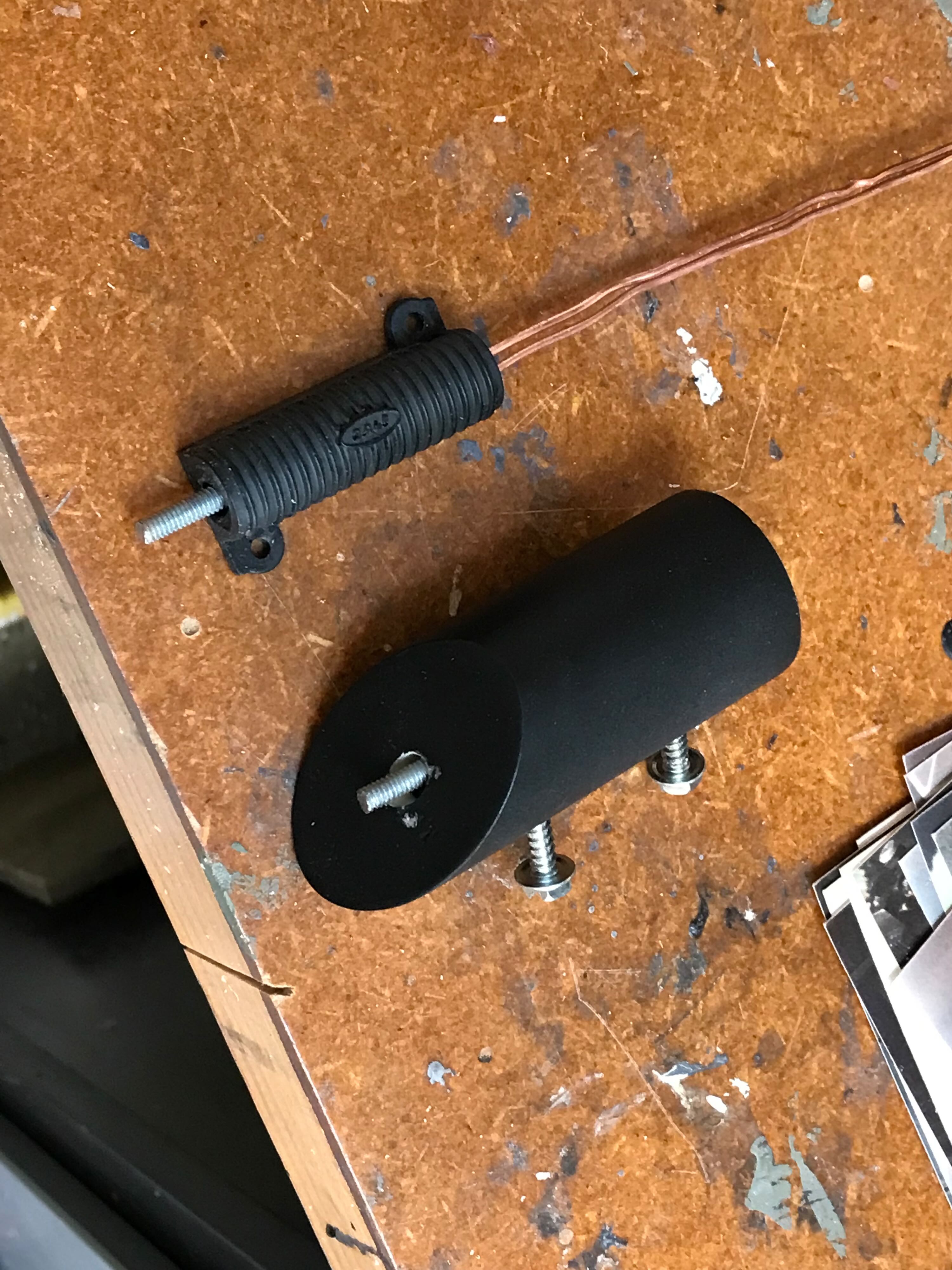
I tapped 4-40 threads into the connector on the Ion Arm metal piece and screwed in a short length of threaded rod I had kicking around. I would have to epoxy this into the hole in the part as I didn’t have the clearance to screw in the connector.
I drilled and tapped 1/4" threaded holes into the injectors to secure them to the shell. I had a little trouble determining which part faced the front of the shell.
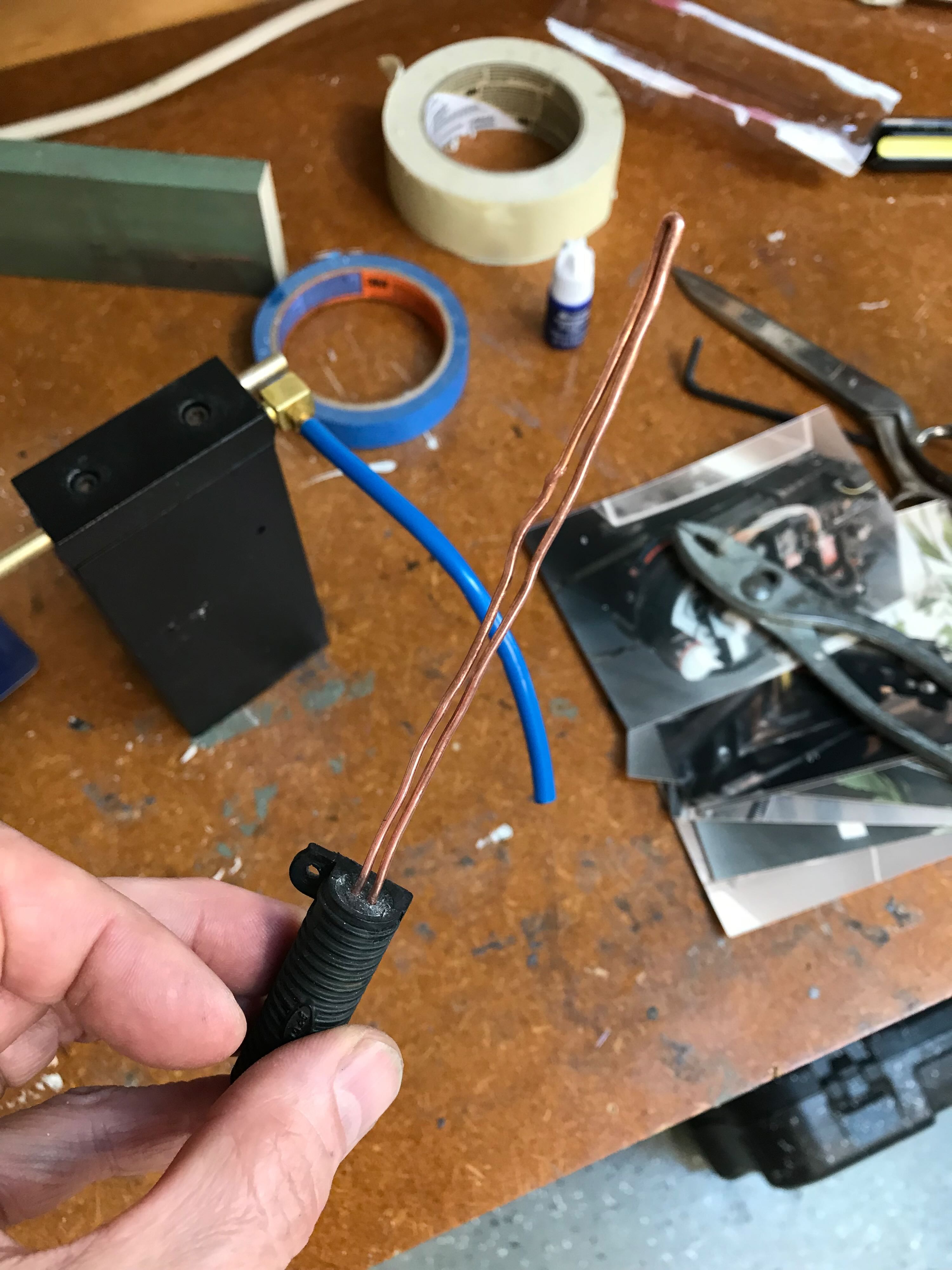
I tapped a 4-40 hole into the brass connector and screwed that into a threaded hole on this pipe. The connector should be hexagonal, but my goal was to use every usable part Wes had purchased.
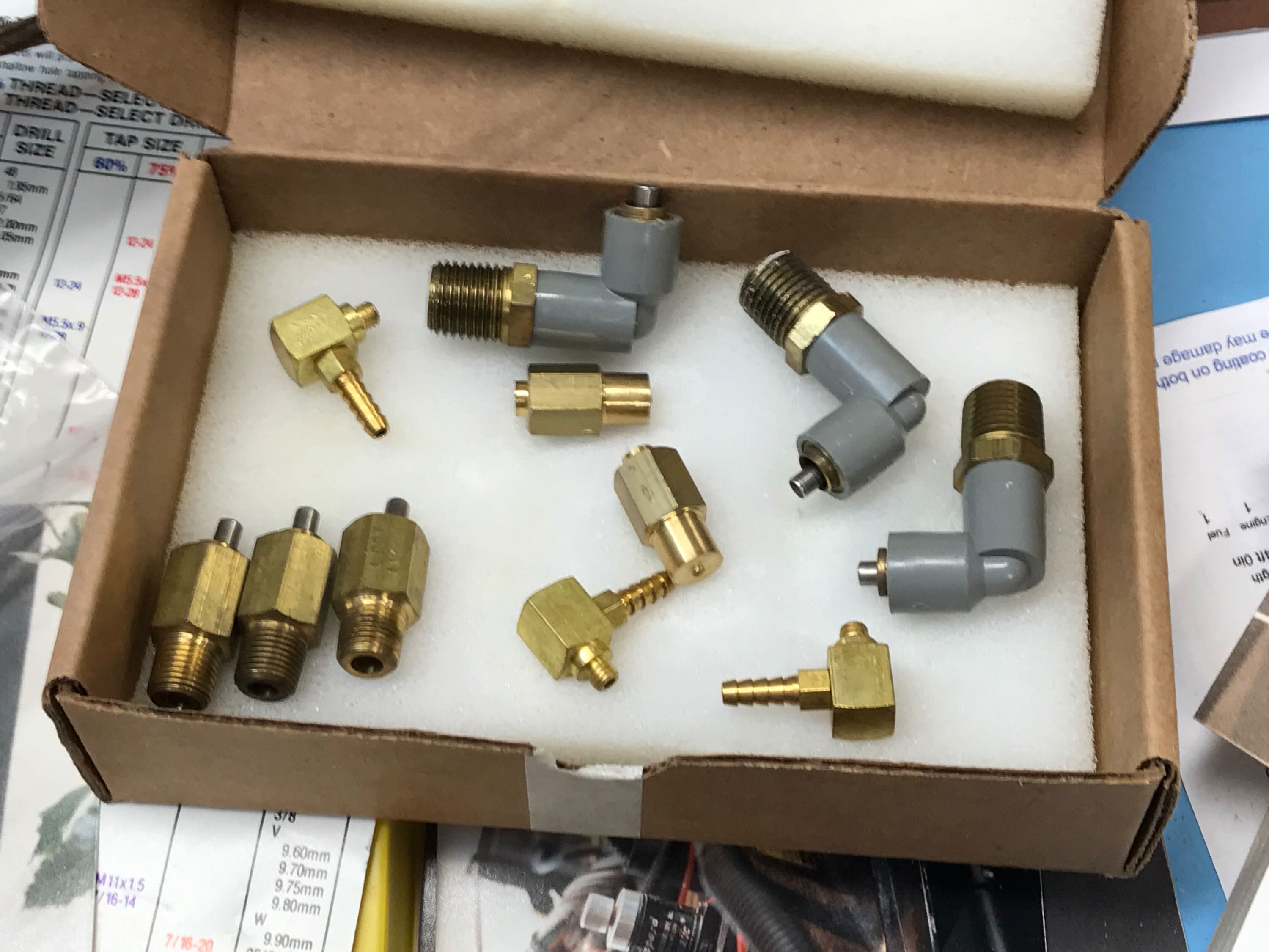
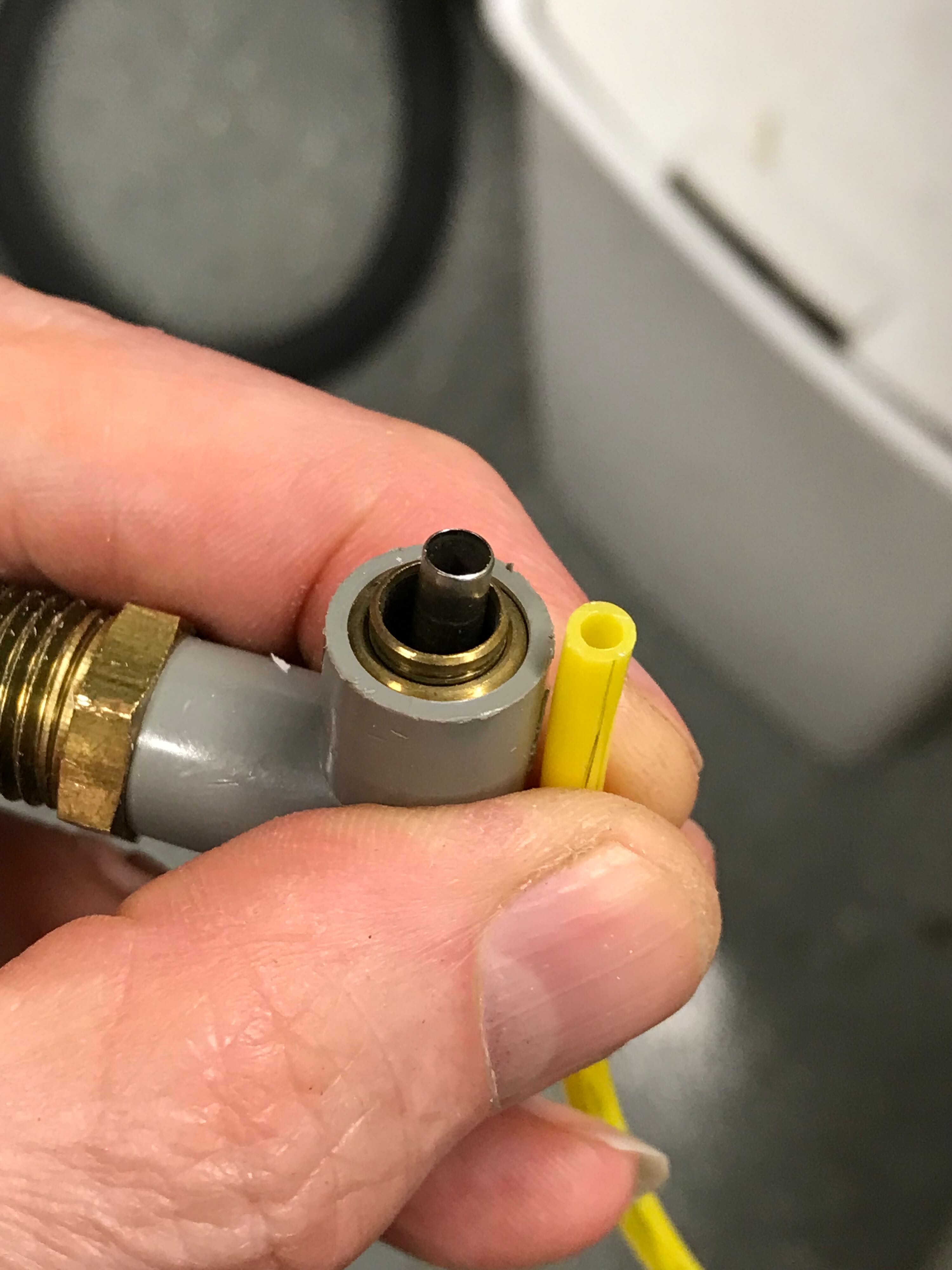
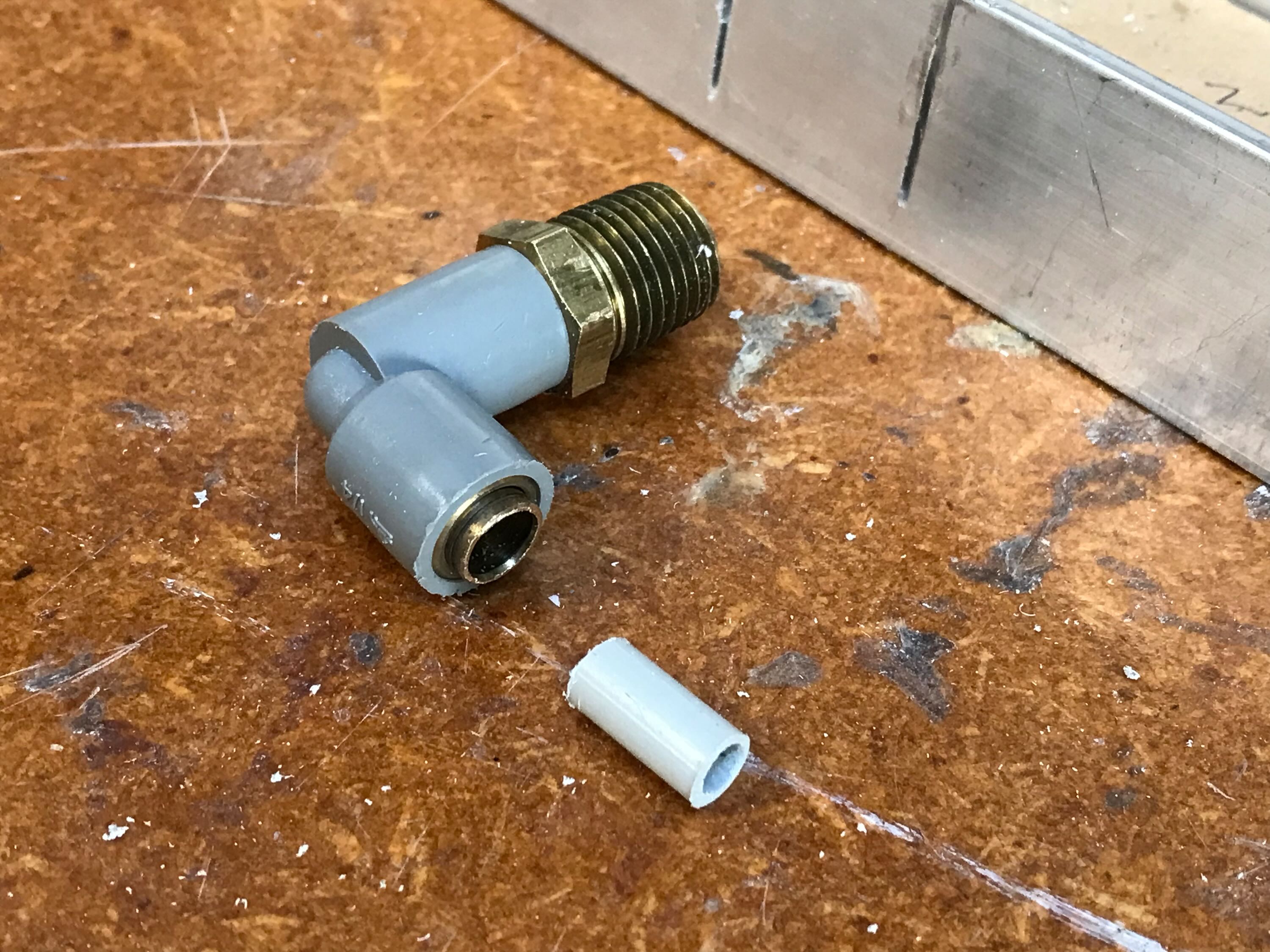
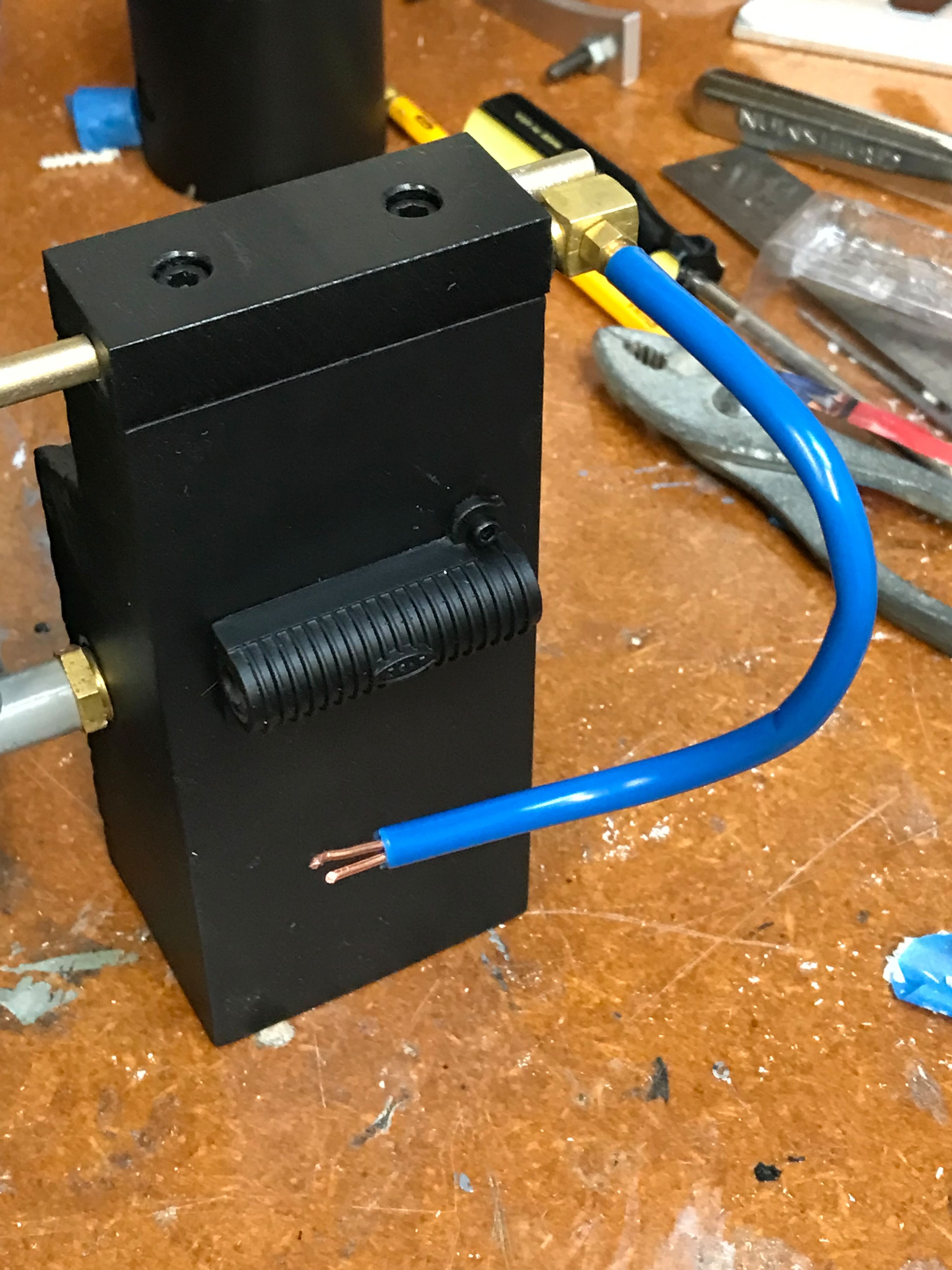
6/23/22 - I ran into some problems with the Legris Elbows that Wes had purchased; the inner metal connectors prevented the thinner tubing from being plugged into them.
After some trial and error I ended up either yanking out, drilling out, or grinding out the inner metal parts that blocked the tubing. Unfortunately I melted a bit of two of the elbows while drilling out those parts. I then modified some rigid plastic tube I had (routing the inside a bit) and glued those into the Legris Elbows.
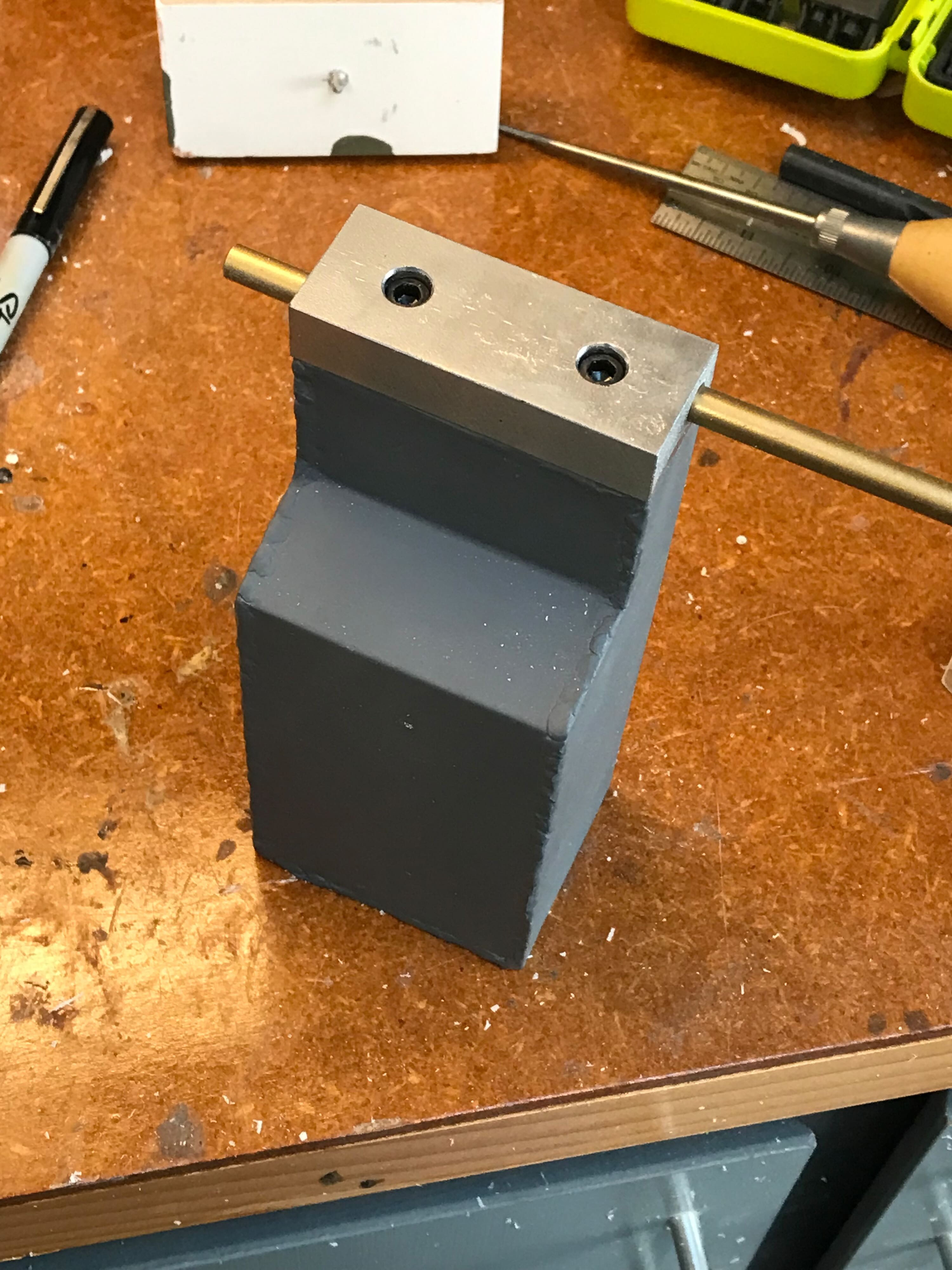
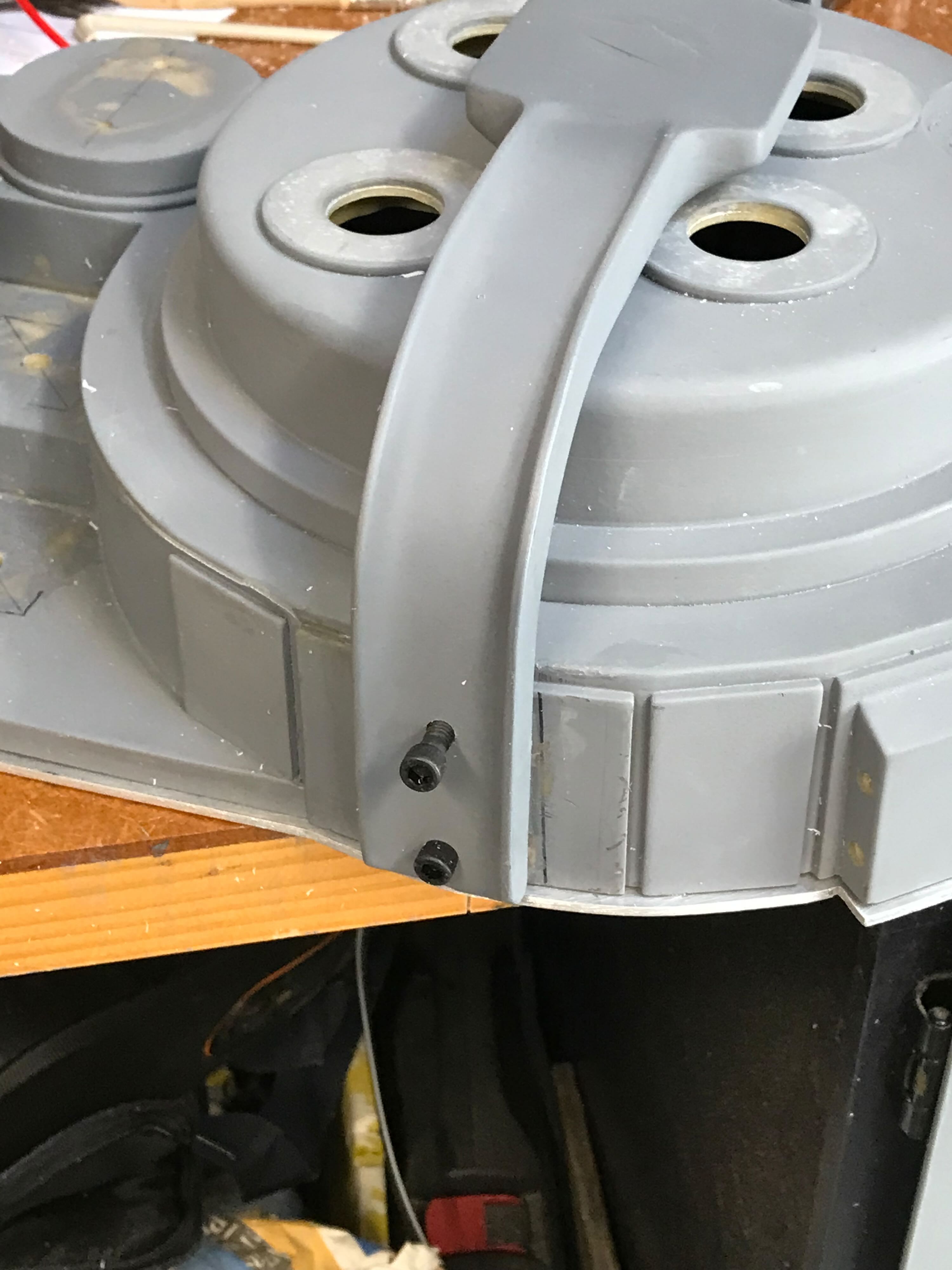
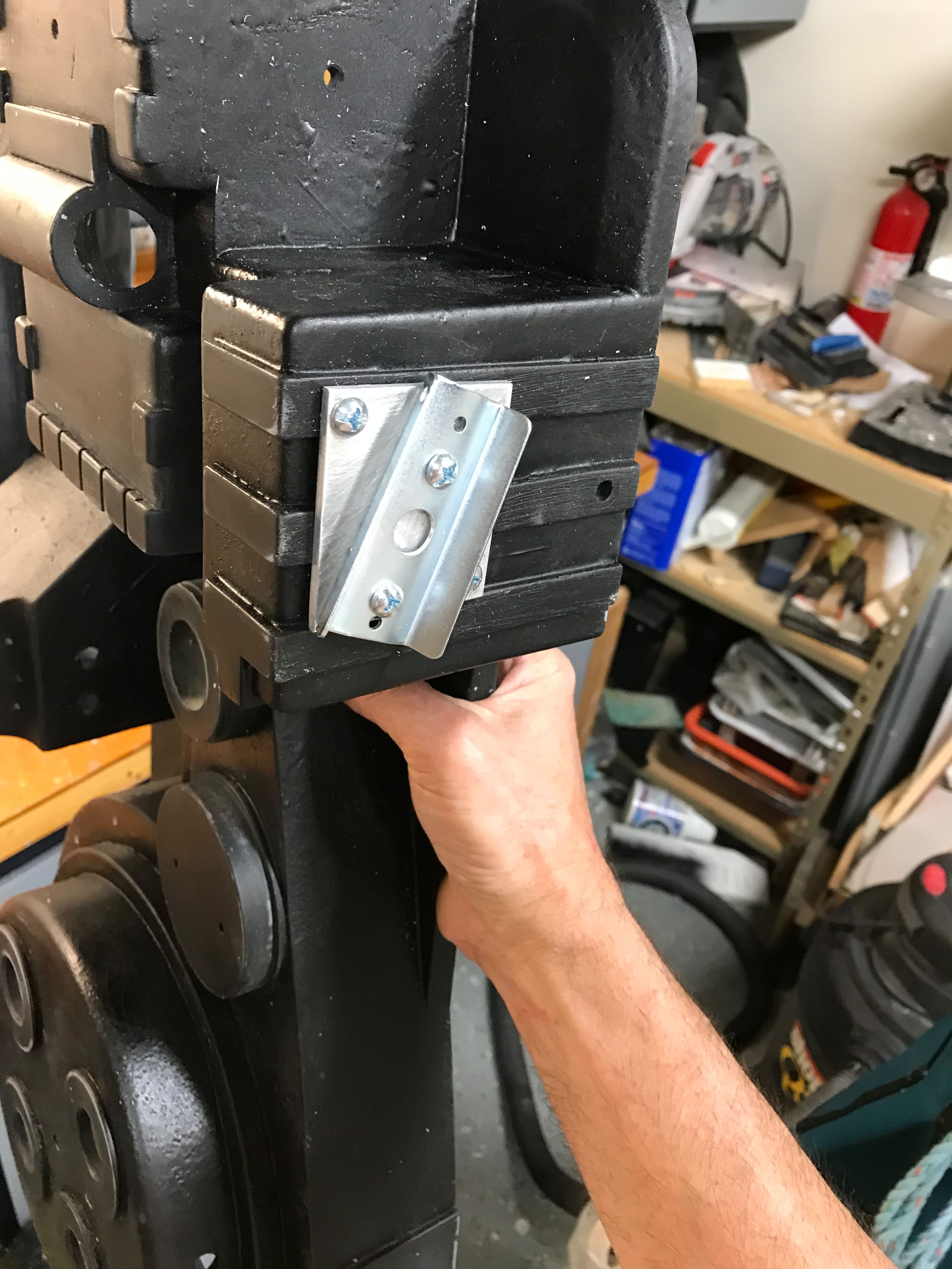
6/24/22 - I drilled holes to mount the bumper, attempting to approximate the positions seen in my 1984 photos. I think the 1/4" socket cap bolts I used are a little too big.
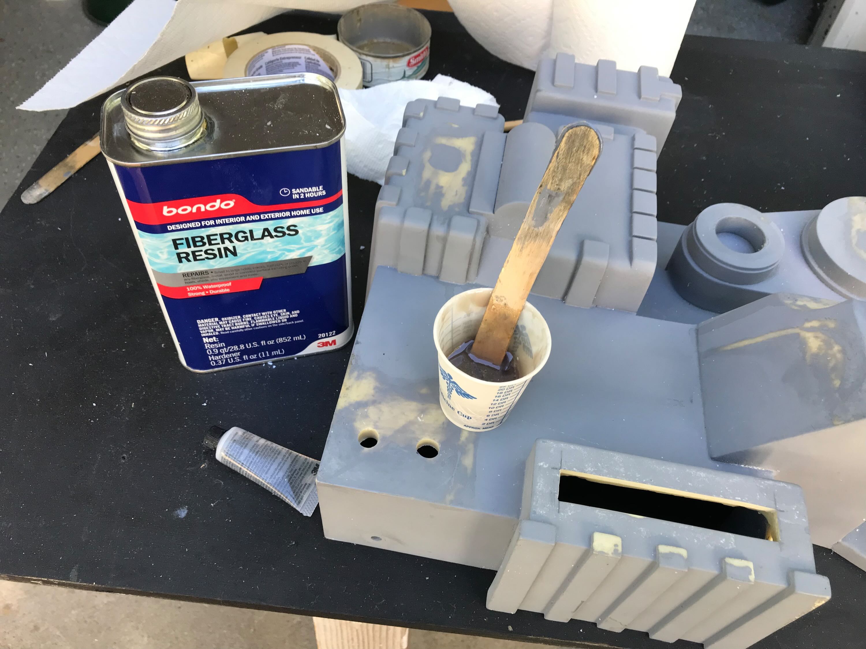
When Bryan and I built our Proton Packs in 1984 I stippled fiberglass resin onto our shells (wood, matt board, fiberglass) to create a rough, cast-iron texture. I decided to use the same technique here. After some trial and error I ended up mixing 1 tsp of Cabosil to 1 oz of resin to thicken it up just a bit to keep it from flowing too smooth.
I stippled the resin onto the various sections over the course of an hour or so, mixing batches of resin in 1/4 oz. increments so I could cover those areas before it set up too fast. In retrospect I probably could have added a tiny bit more Cabosil to thicken the resin a bit more to create a more pronounced texture.
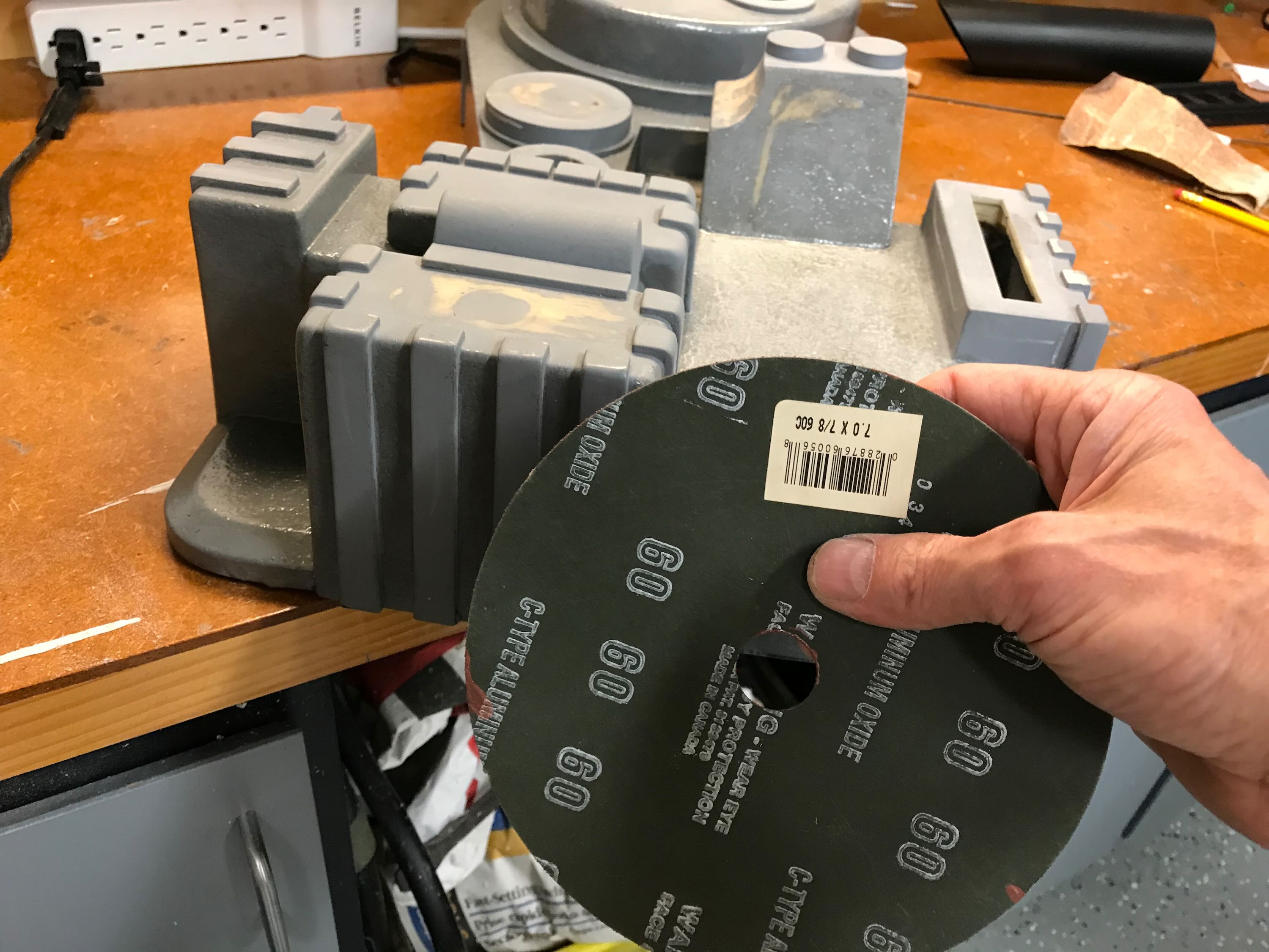
I roughened up the appropriate slats on the various parts with 60 grit sandpaper. This was the roughest sandpaper I had, and I just hand sanded the slats along their length.
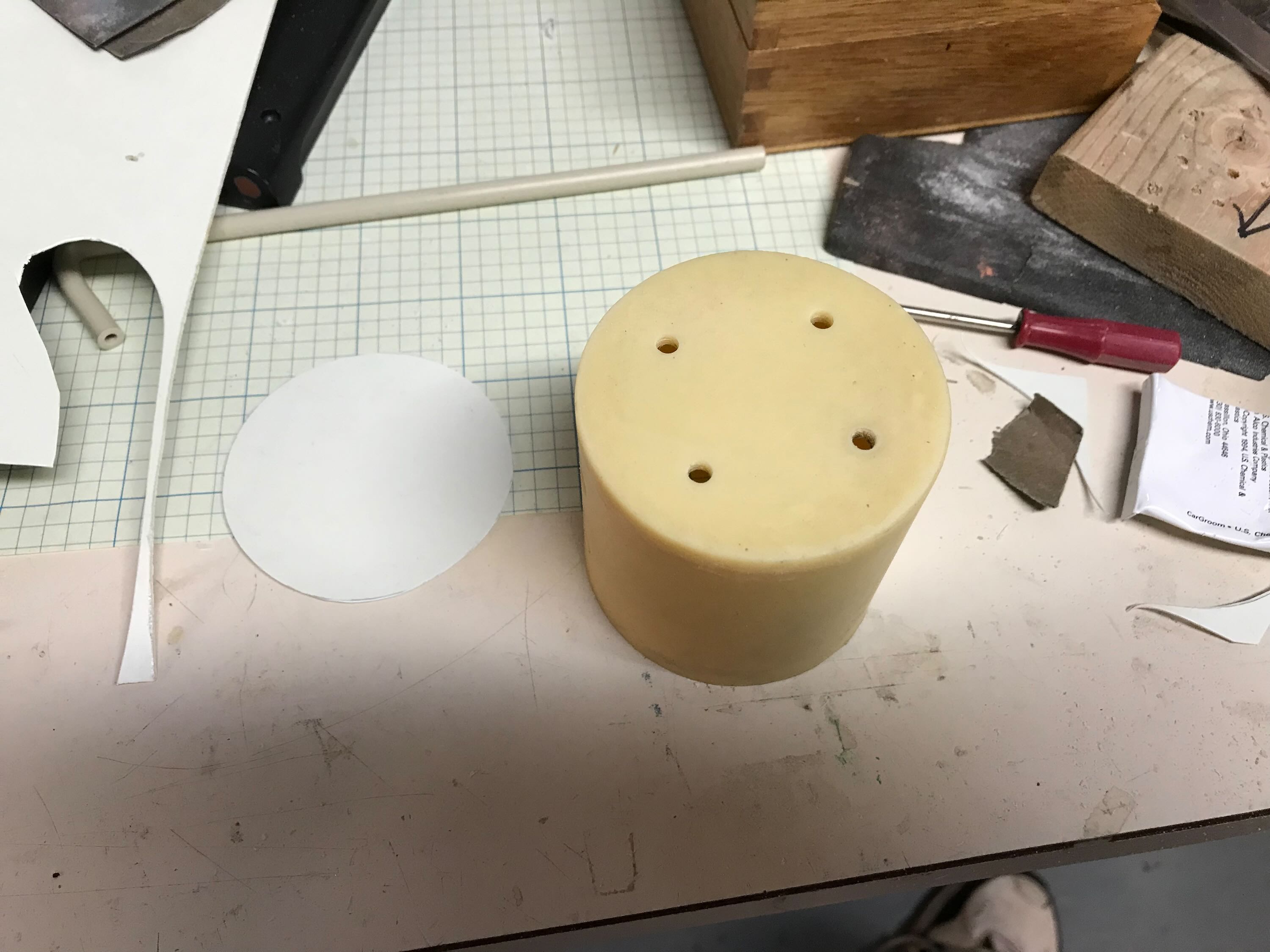
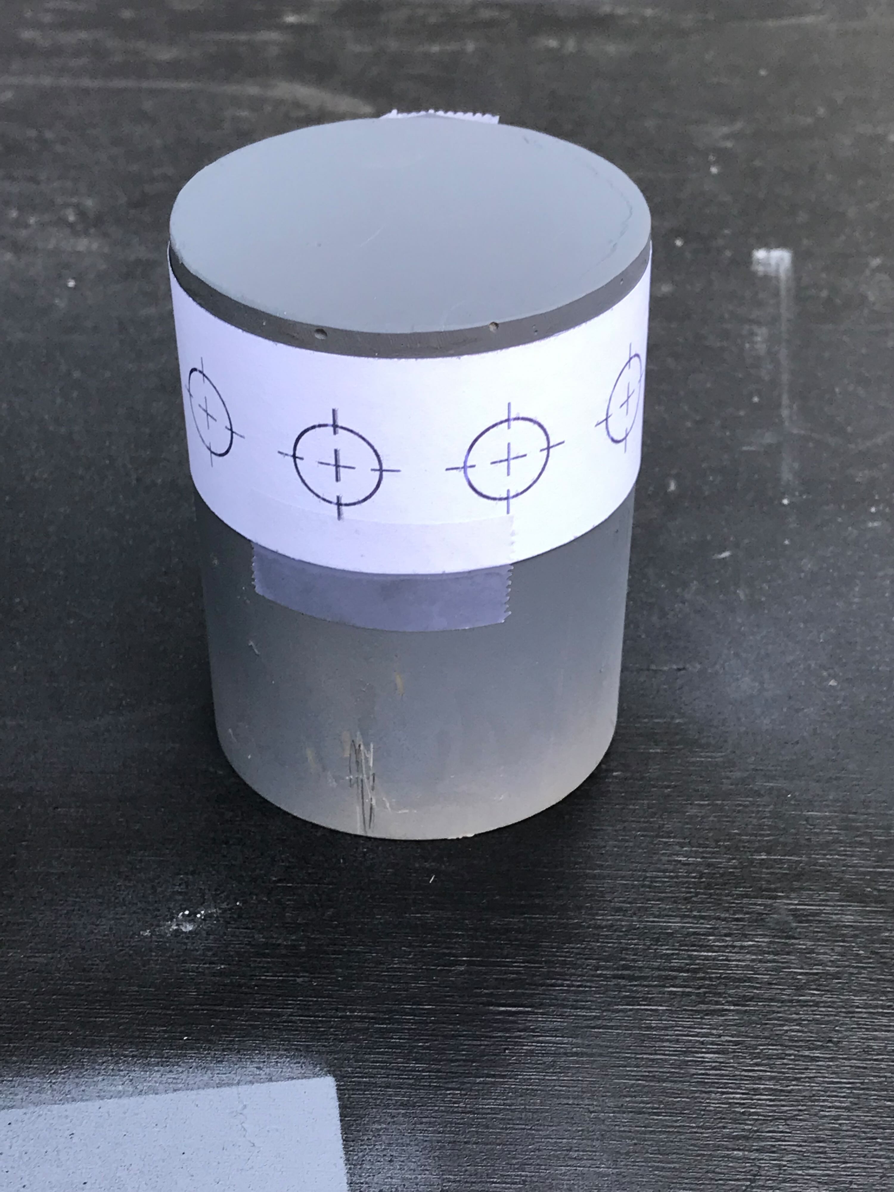
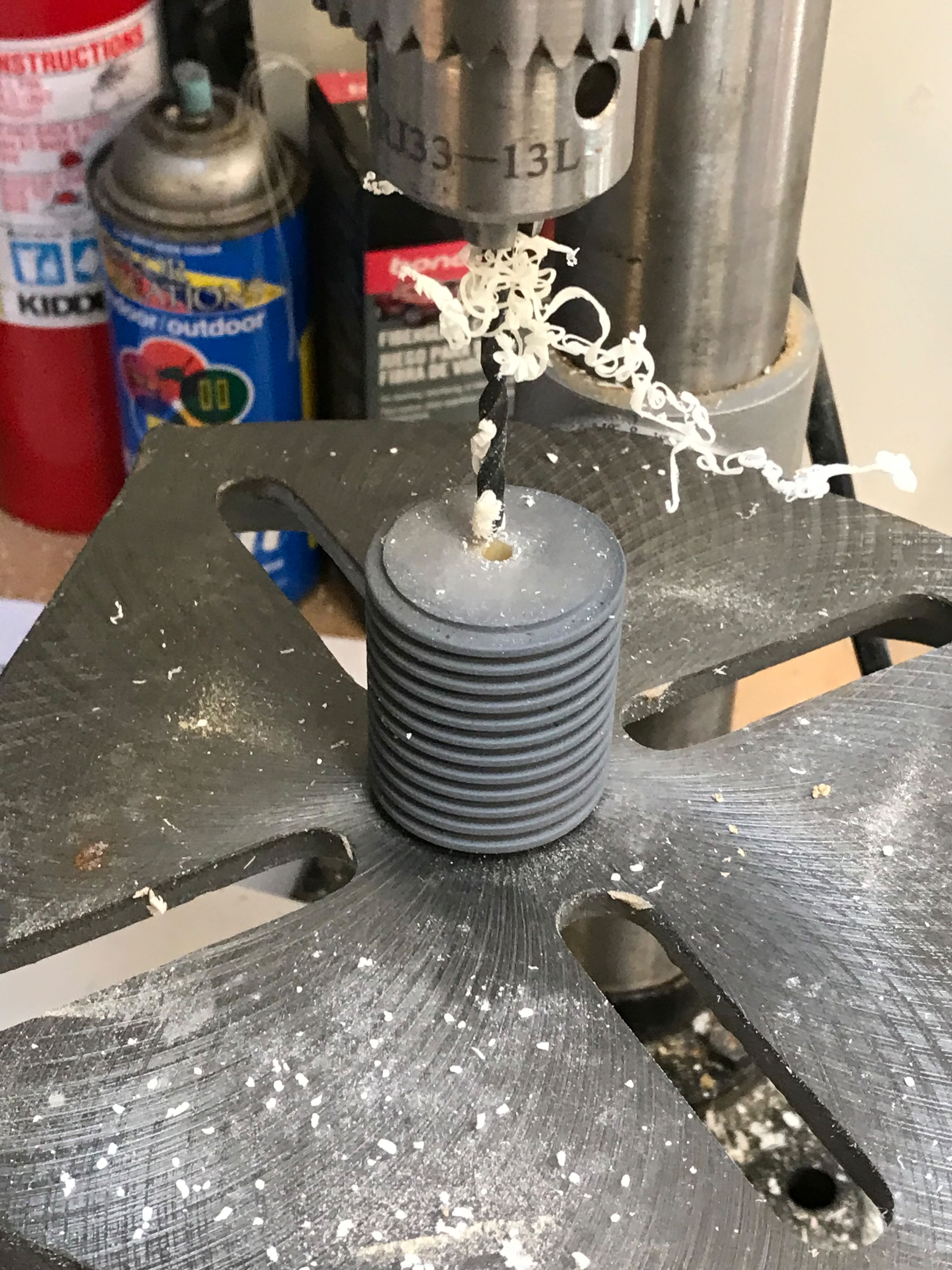
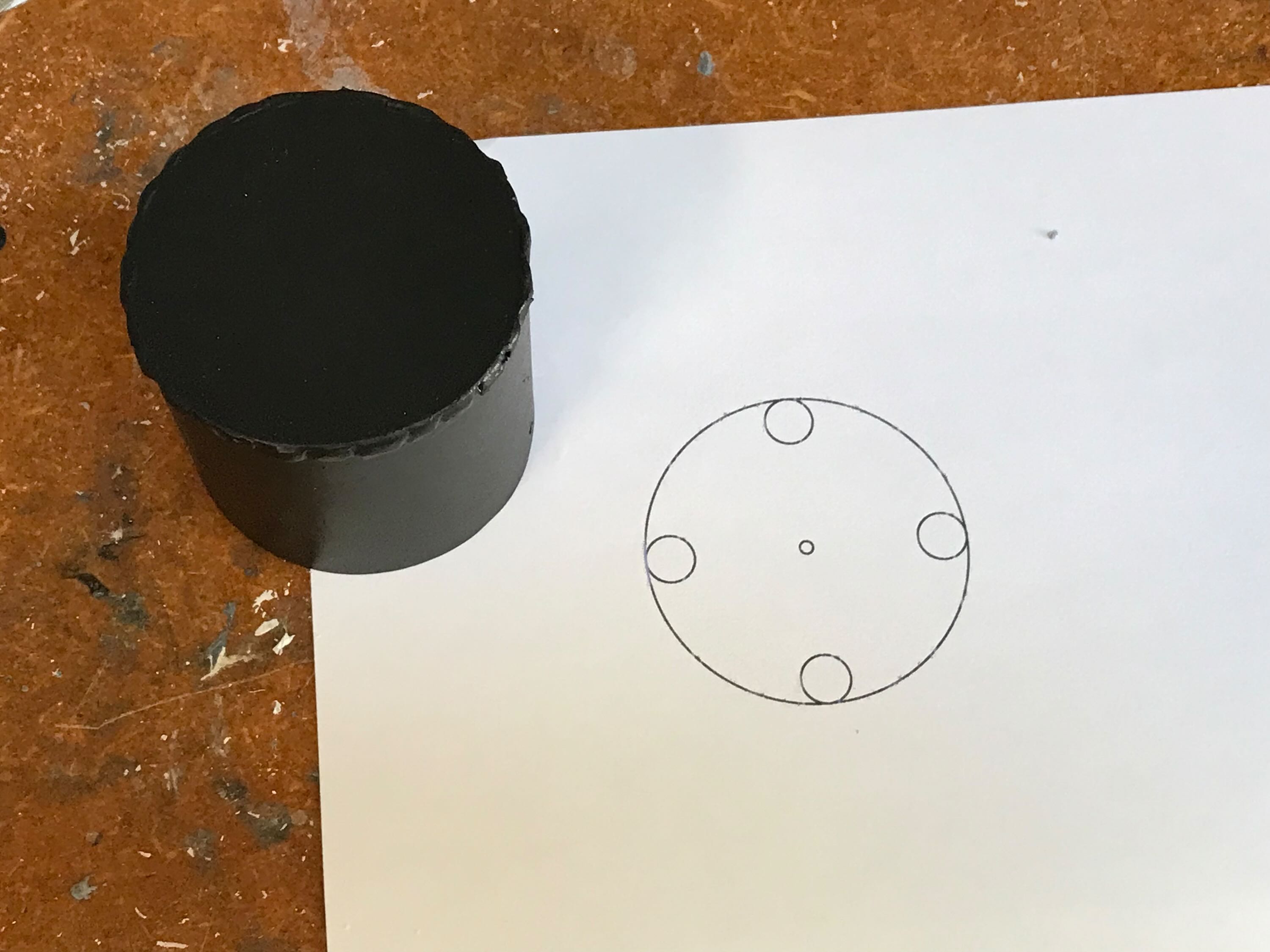
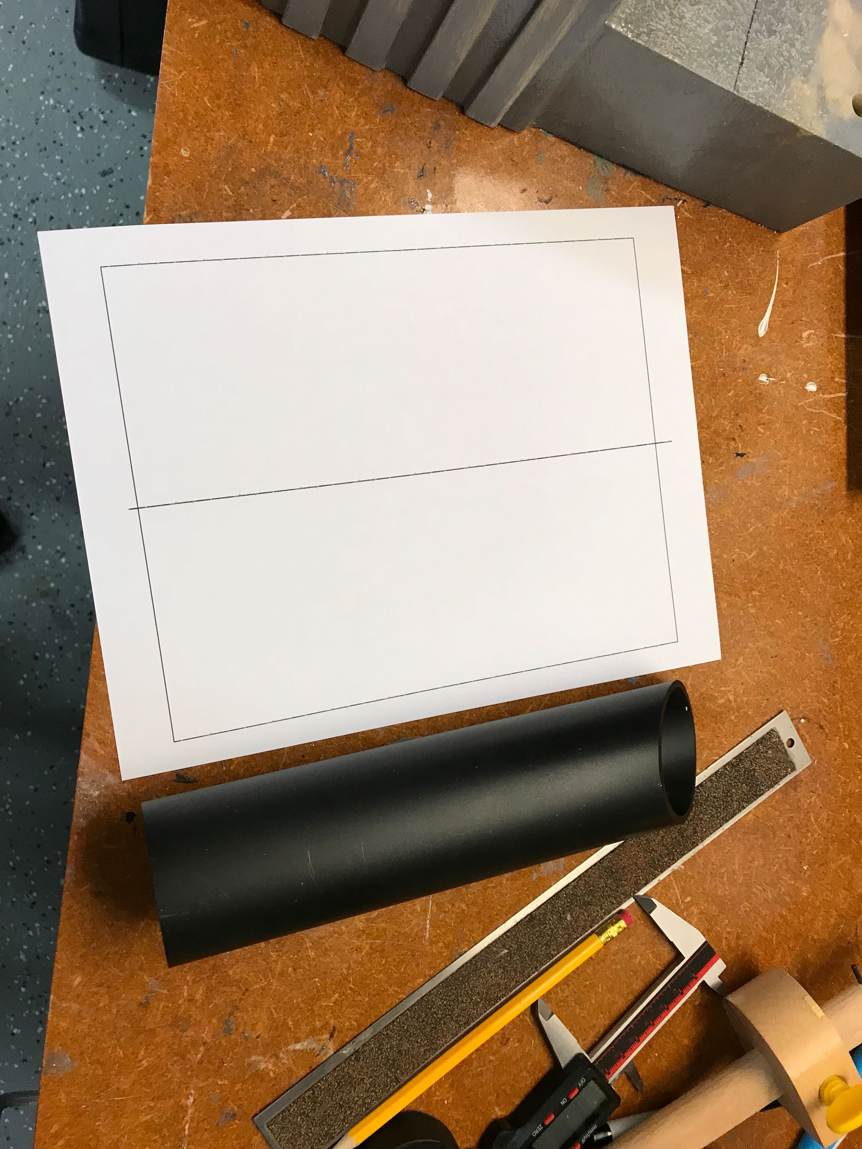
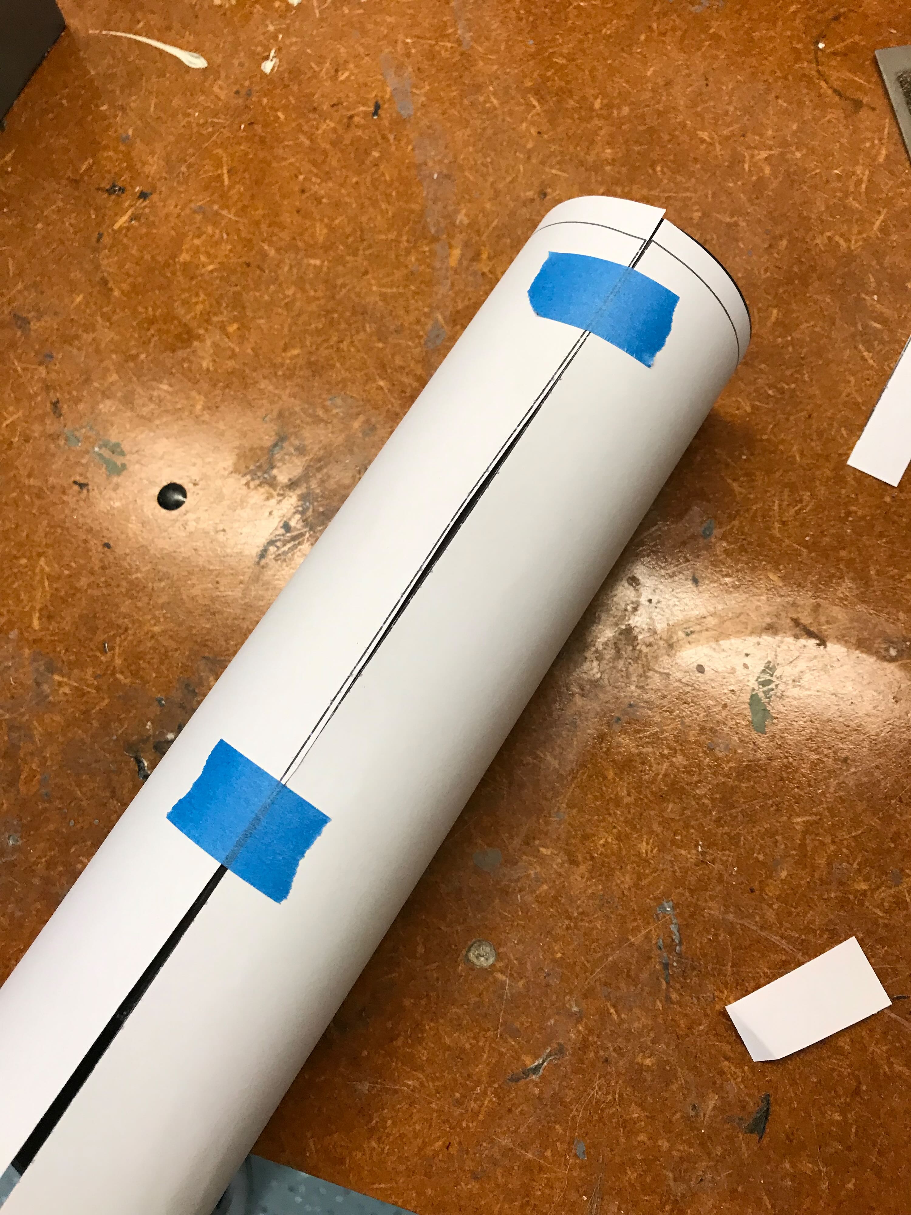
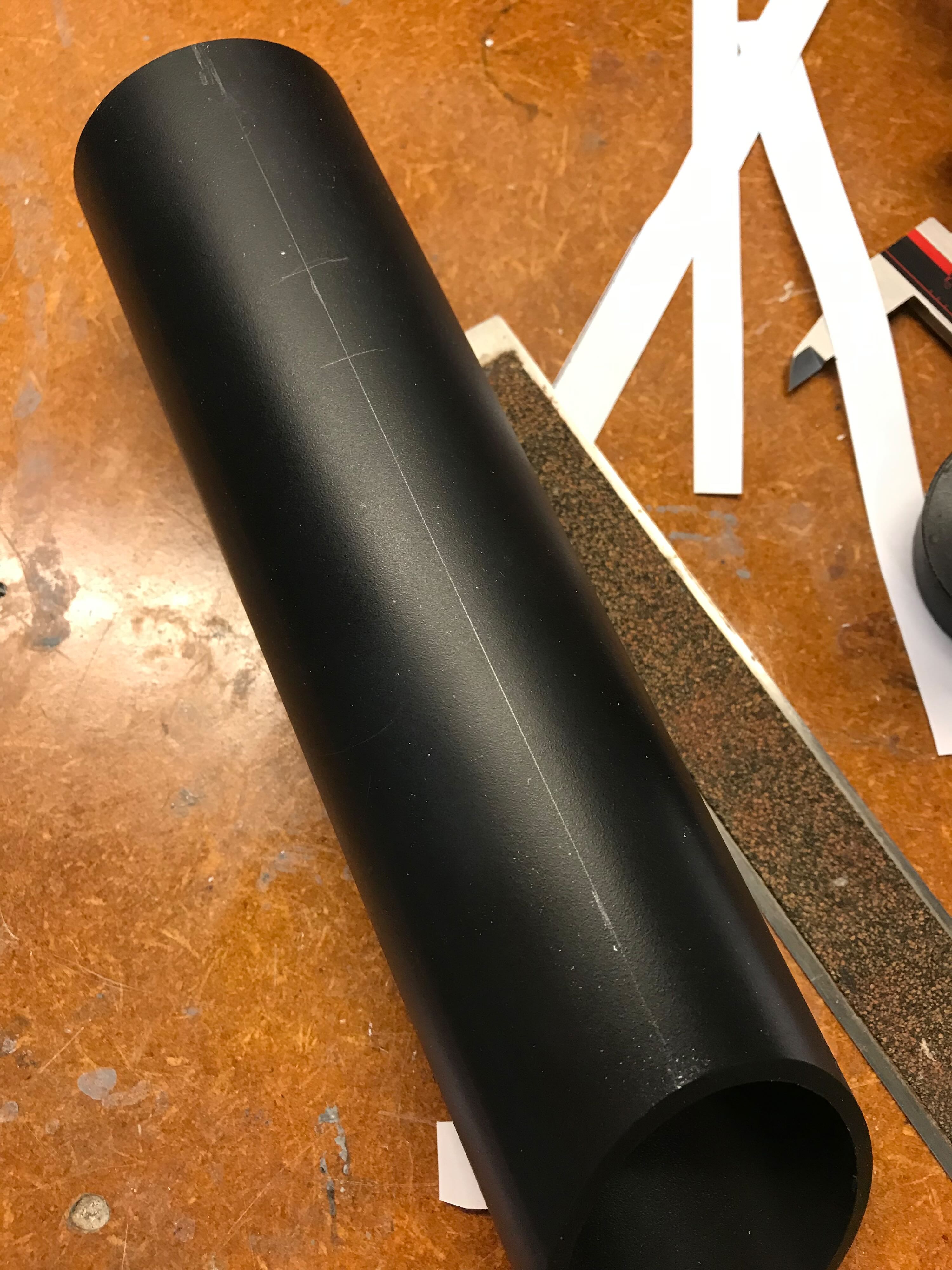
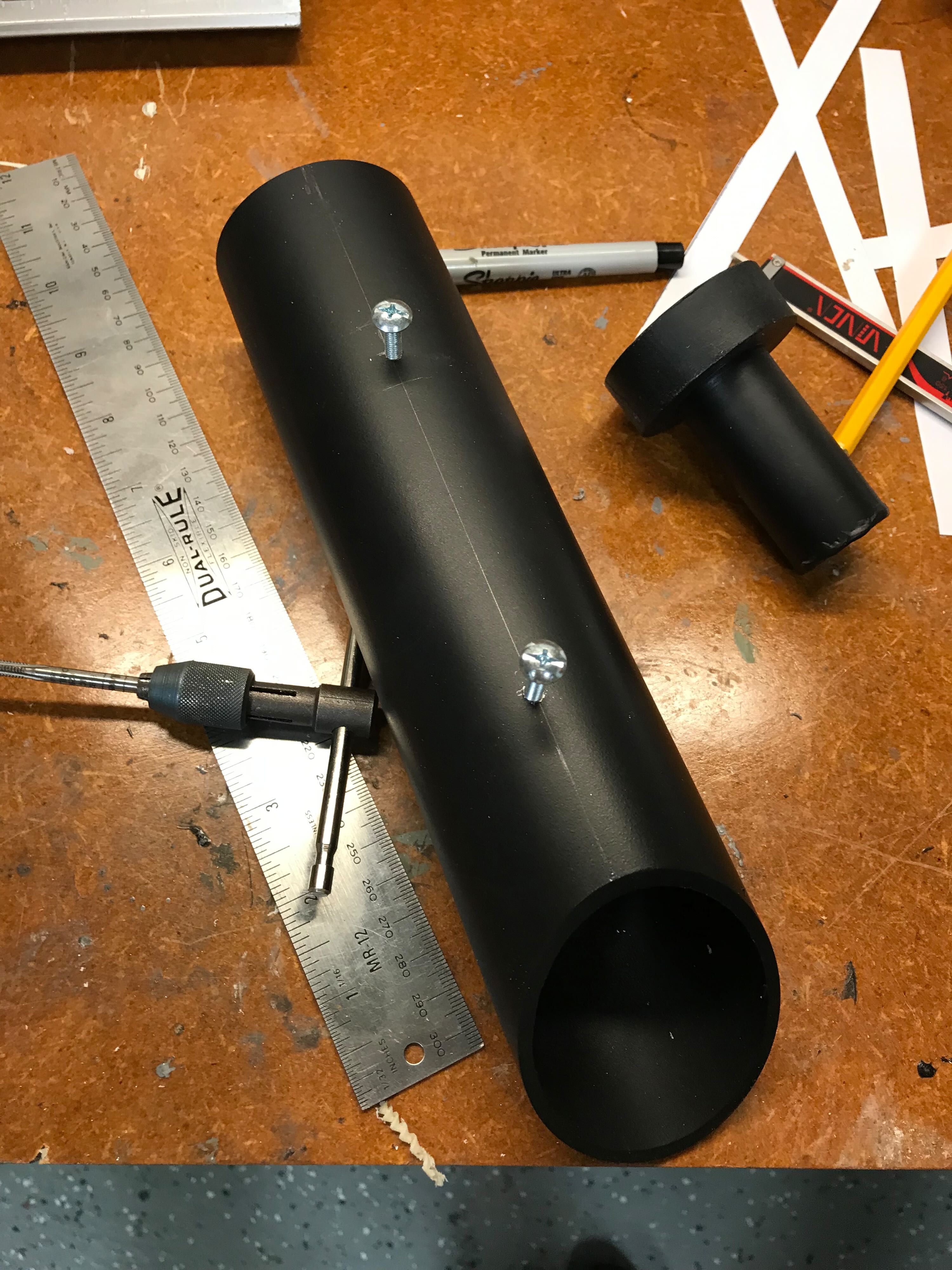
I calculated the circumference of the booster tube and created a template in Illustrator. I could wrap this around the tube to help mark a line for the mounting bolts, which I drilled and tapped into the aluminum tube.
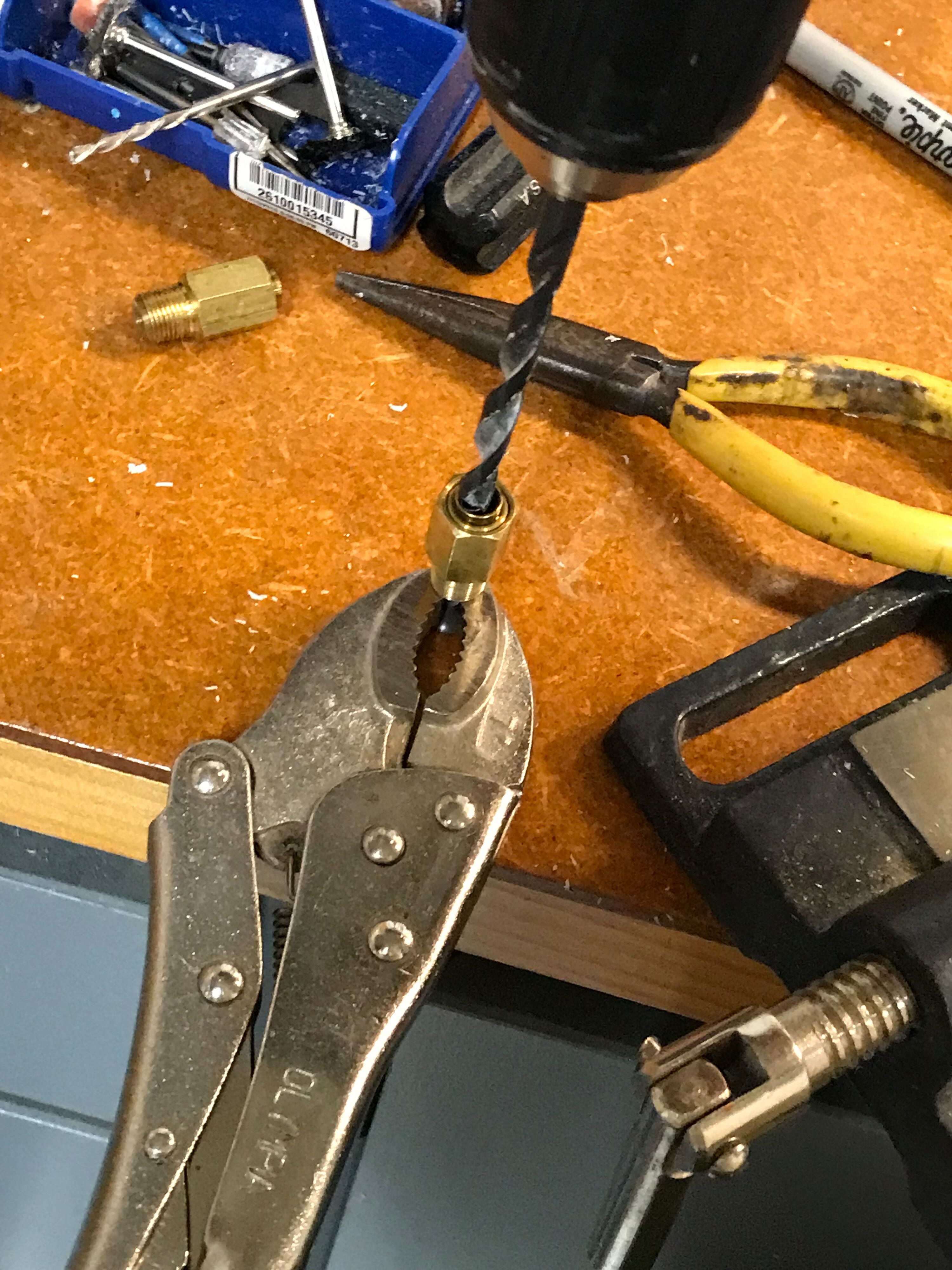
6/26/22 - As with the elbow connectors, I had to drill out the inner parts of the straight connectors to accommodate the thinner tubing. I jammed a screw into the opposite end to grab the metal connector so it wouldn’t spin when I drilled and Dremeled it out.
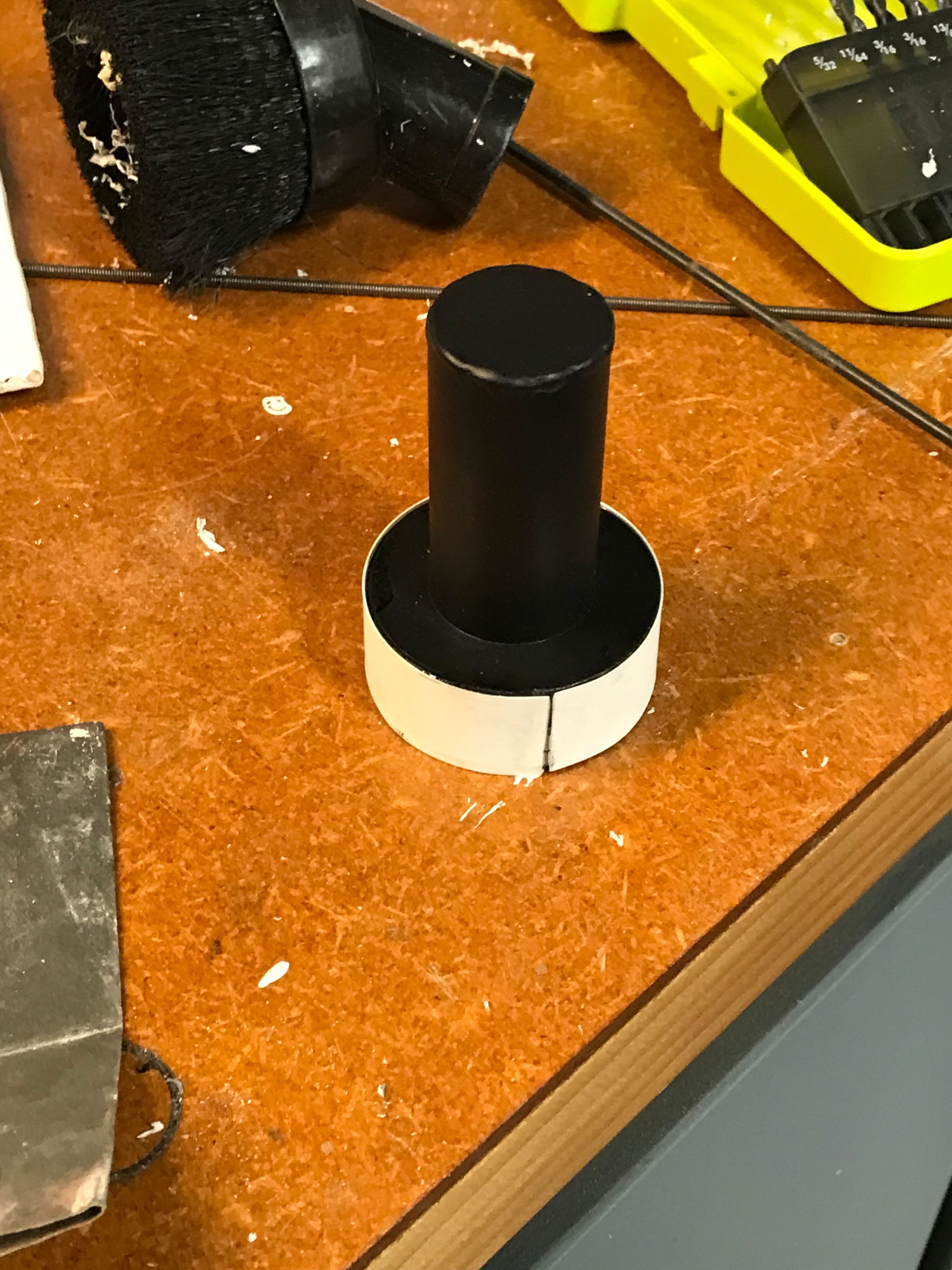
The resin booster tube plug was very wobbly inside the aluminum tube, so I epoxied some thin plastic around its circumference to create a tighter fit. I would epoxy this into the tube with the top mounting bolt going into it too.
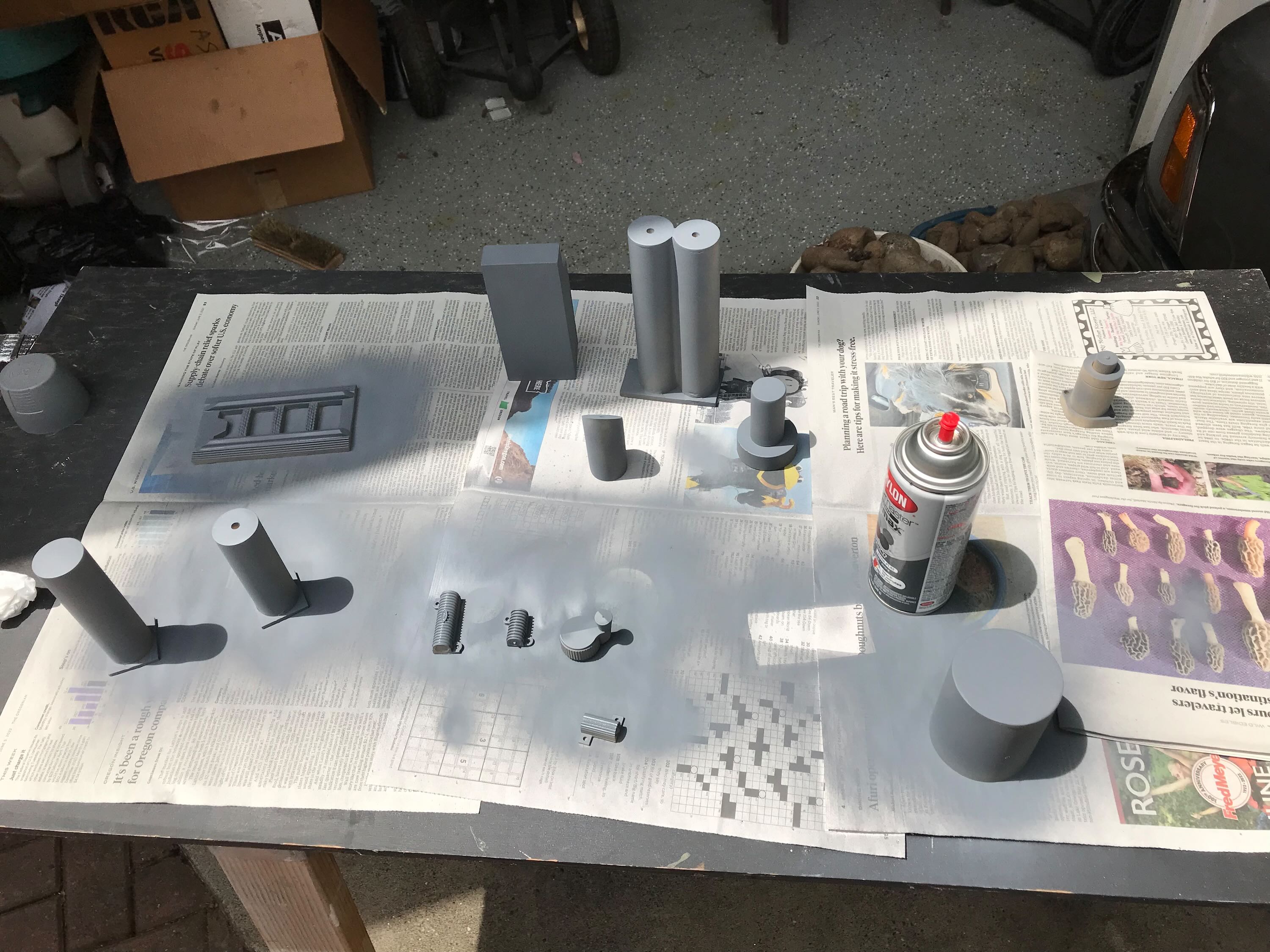
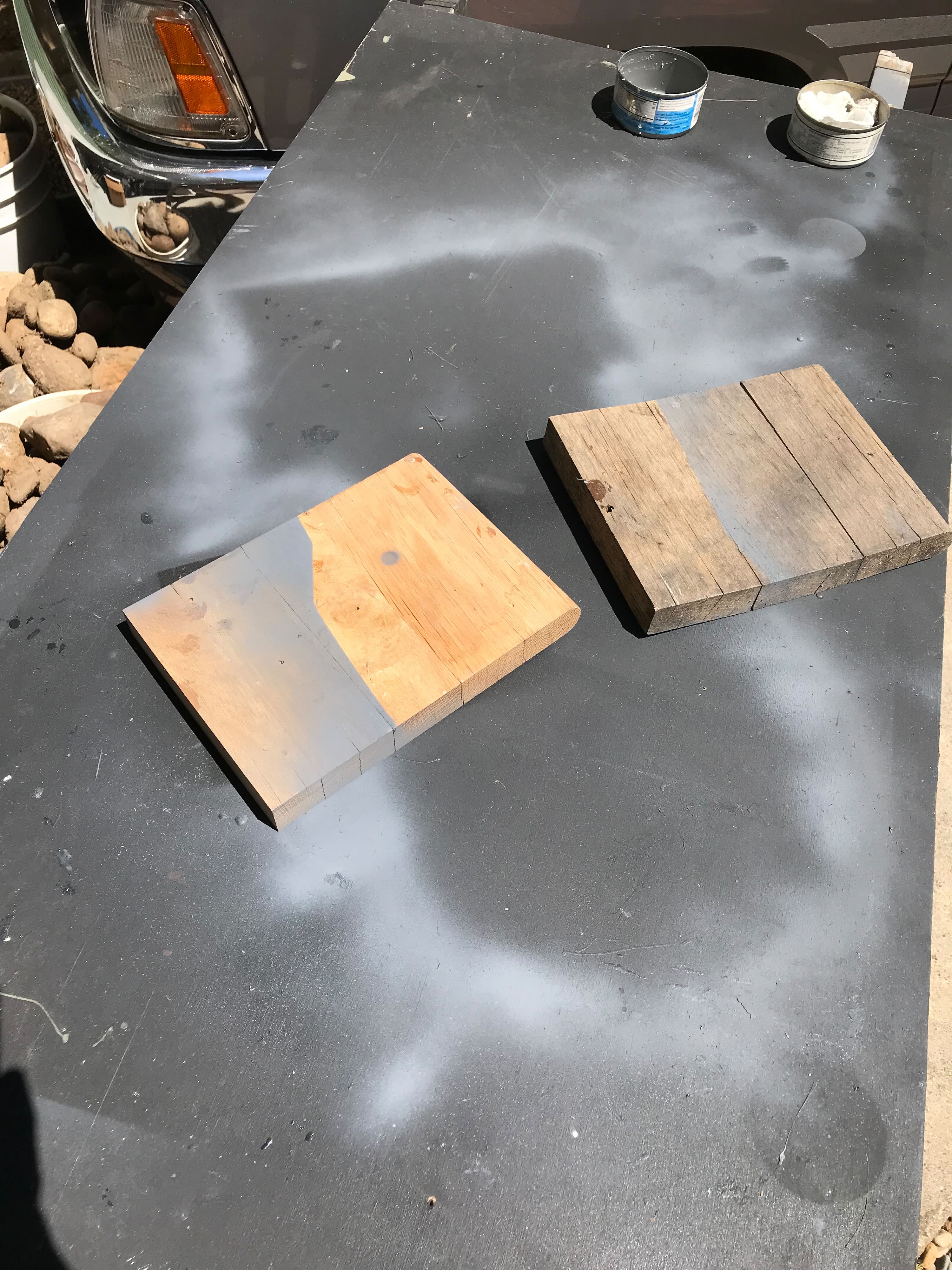
I painted the main shell with Rustoleum Satin Black. I had a lot of trouble getting an even finish, so I later oversprayed this with Krylon Clear Satin. This helped even out the sheen, especially the very glossy areas.
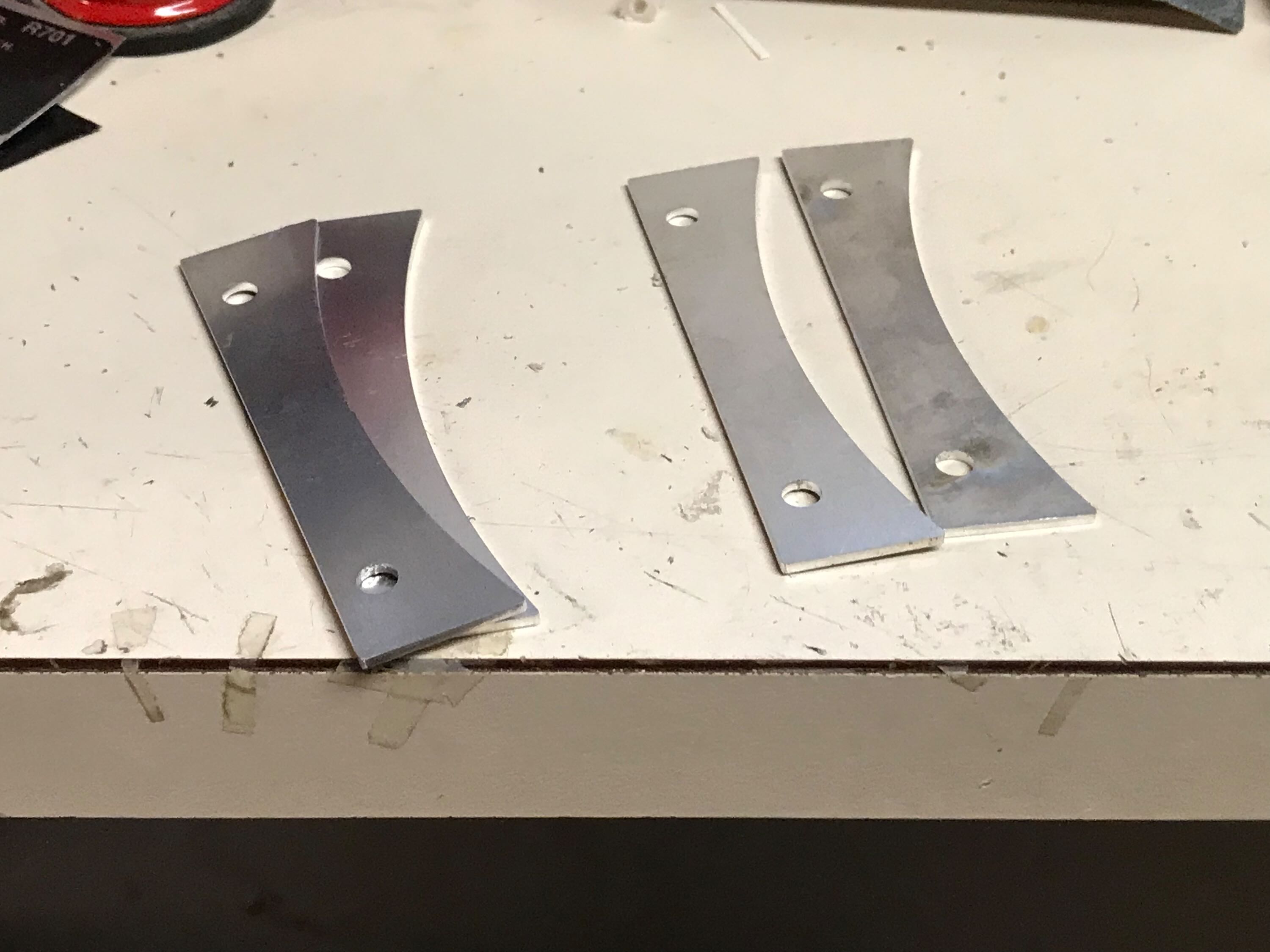
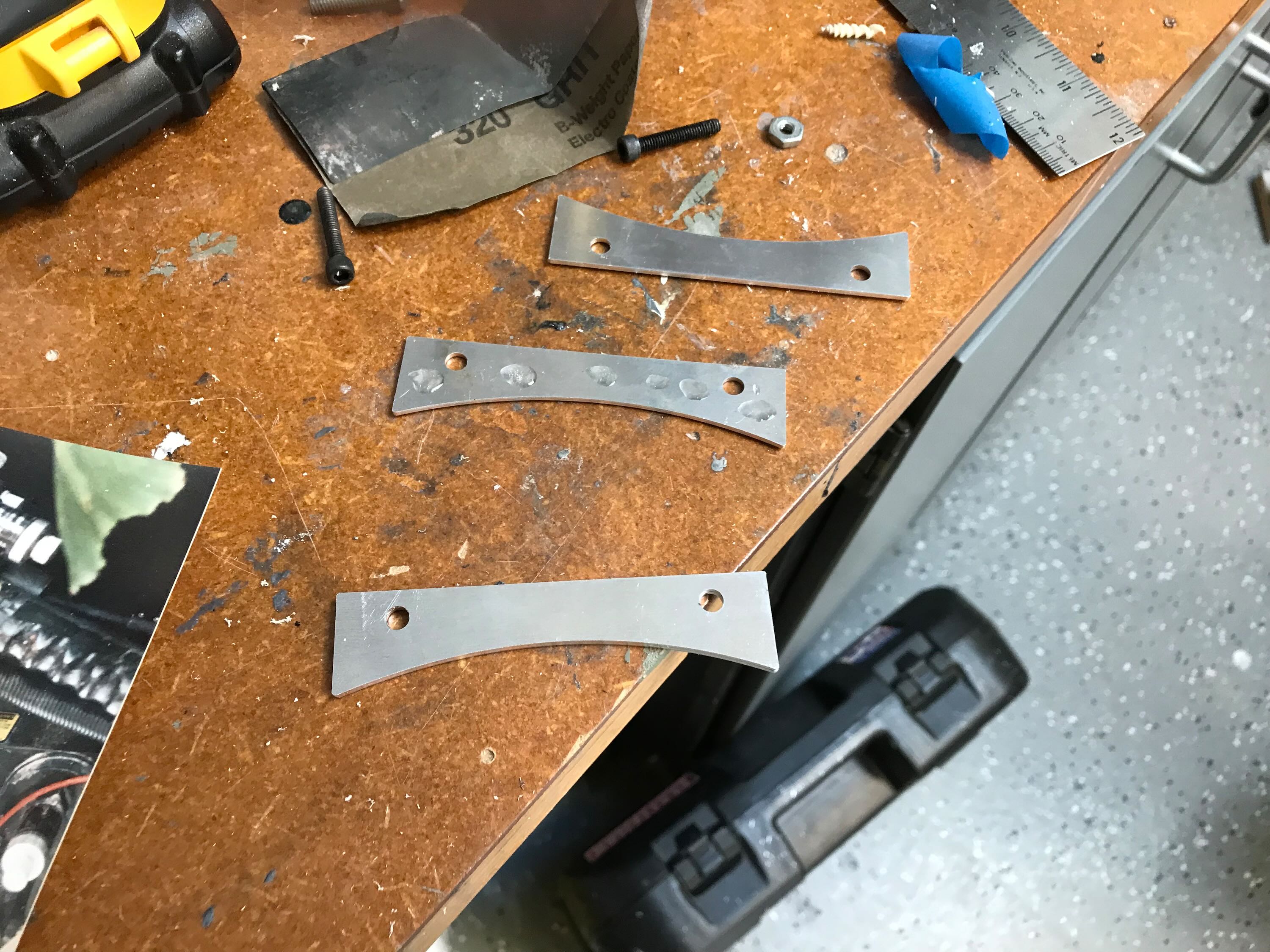
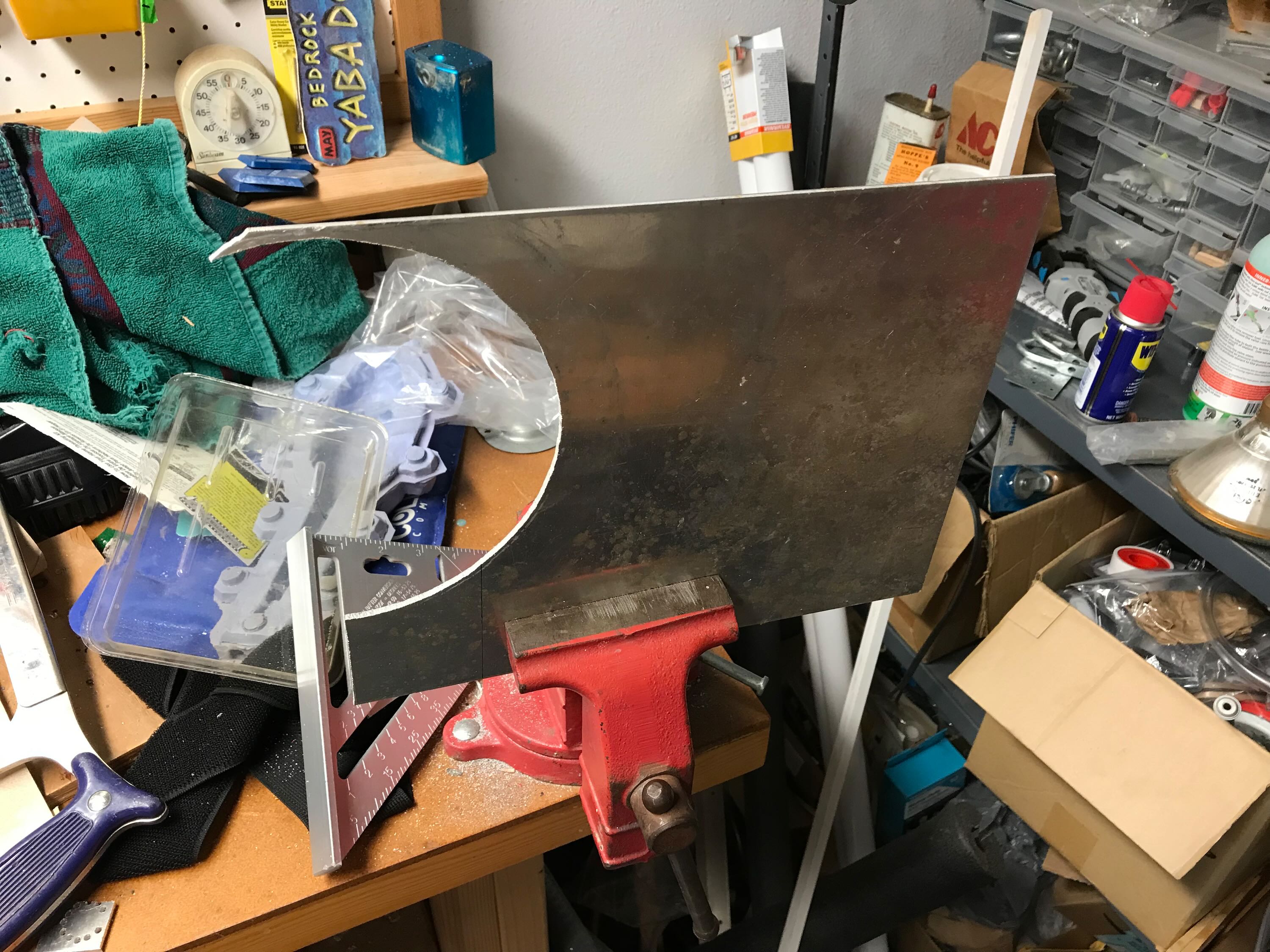
The V-mount kit Wes bought didn’t include the aluminum support plate, so I hacksawed that out of a 1/8" piece of aluminum I’ve had kicking around since the early 90s.
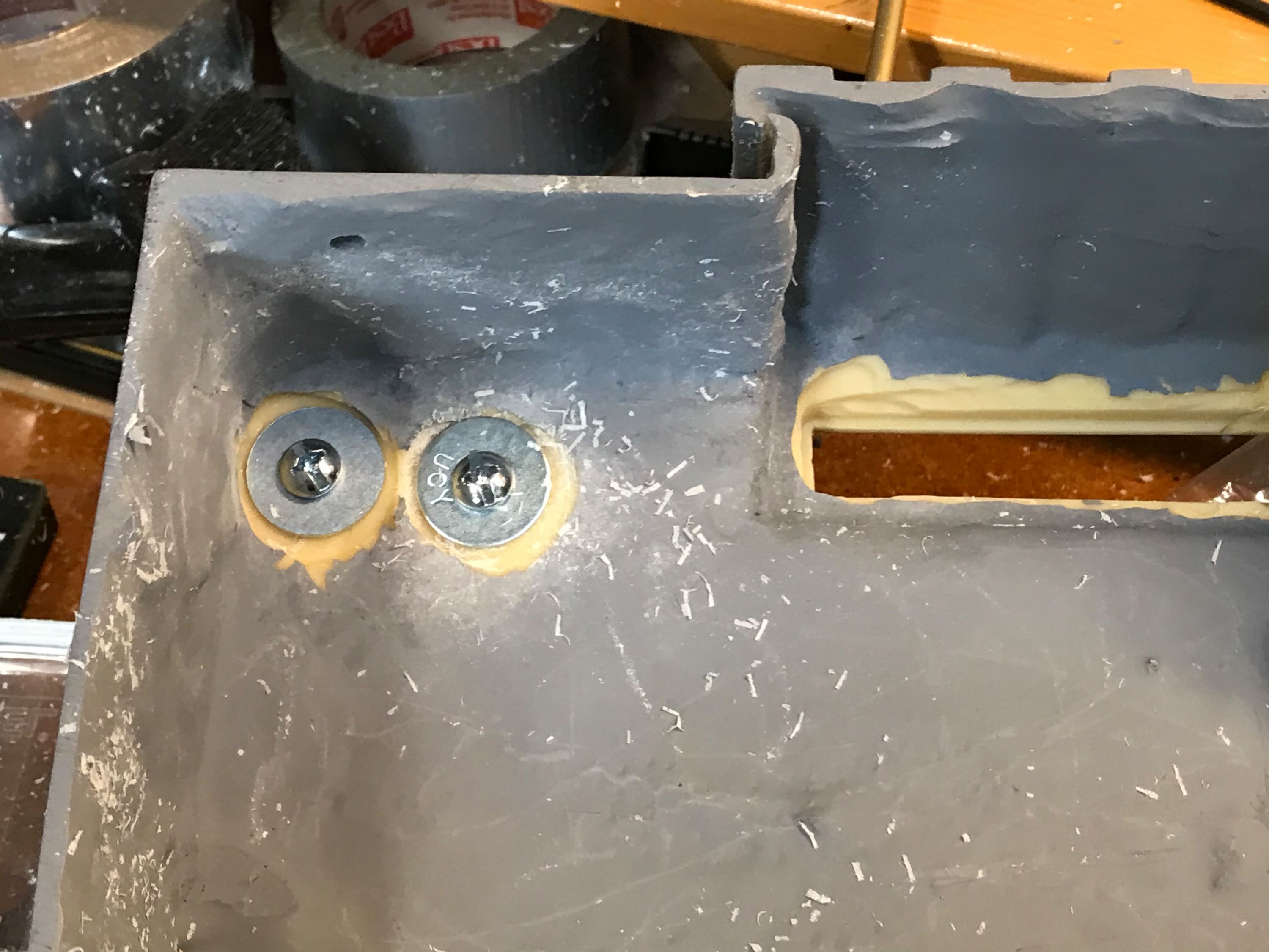
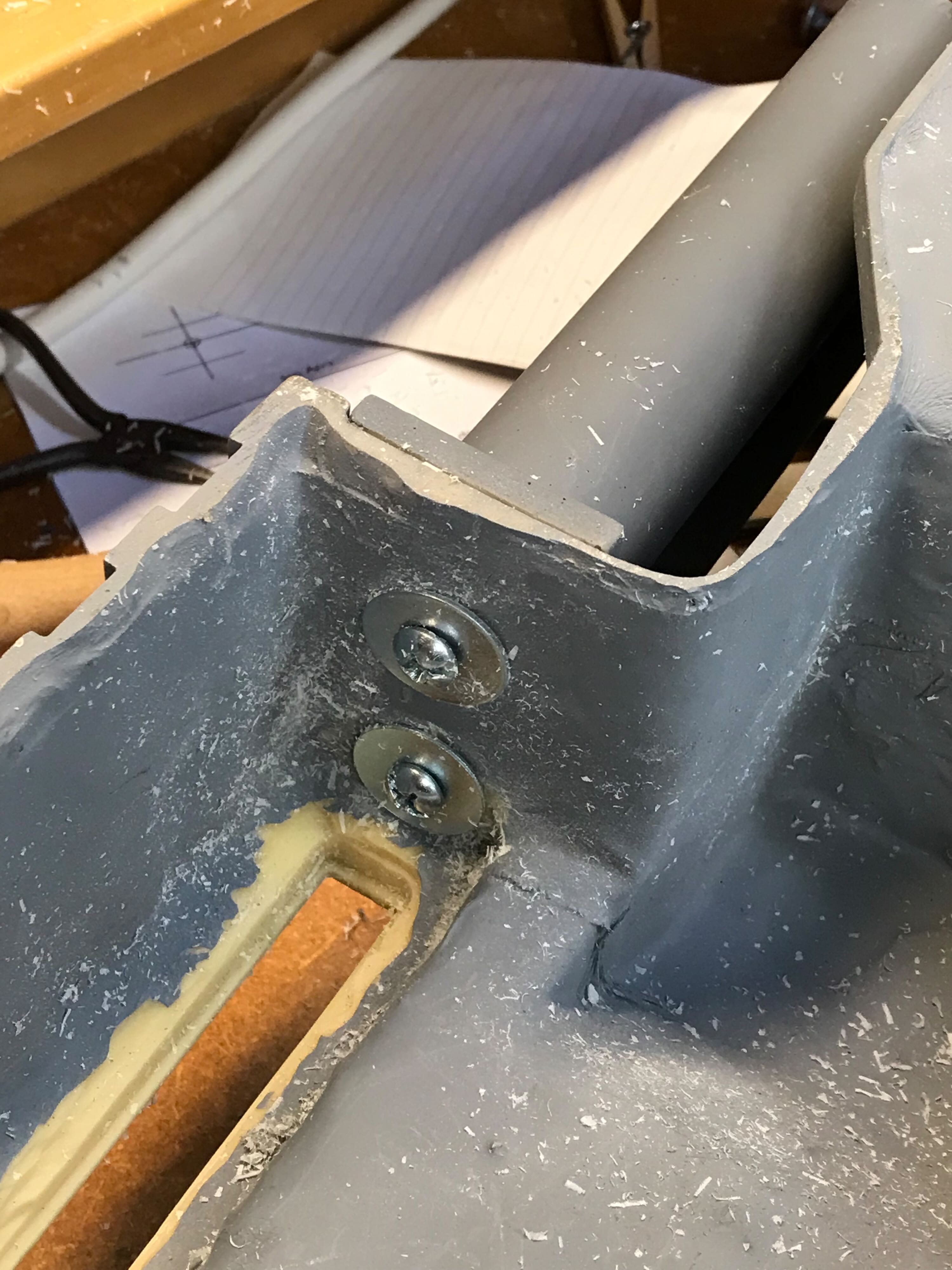
I was able to secure the outer plate to an inner plate with three bolts. The resin was too thick to fully anchor all four bolts, so the top left doesn’t go through the inner plate or bolted to a nut. It seems pretty secure.