EctoLabs Gizmo 8400 Build Thread

It’s here! I ordered up a Gizmo 8400 kit from EctoLabs a few weeks back and I’m ready to get started on it. I was gonna go with my own 3D printed version, but when this came in stock, I figured it really short circuits the effort needed, gets me everything all at once, and I can piddle around in the evening and get it put together. This is just what the initial spread comes out looking like. I’ll be updating as I move forward. I also have a couple ideas for what I’ll do to make it feel more like “my own.”
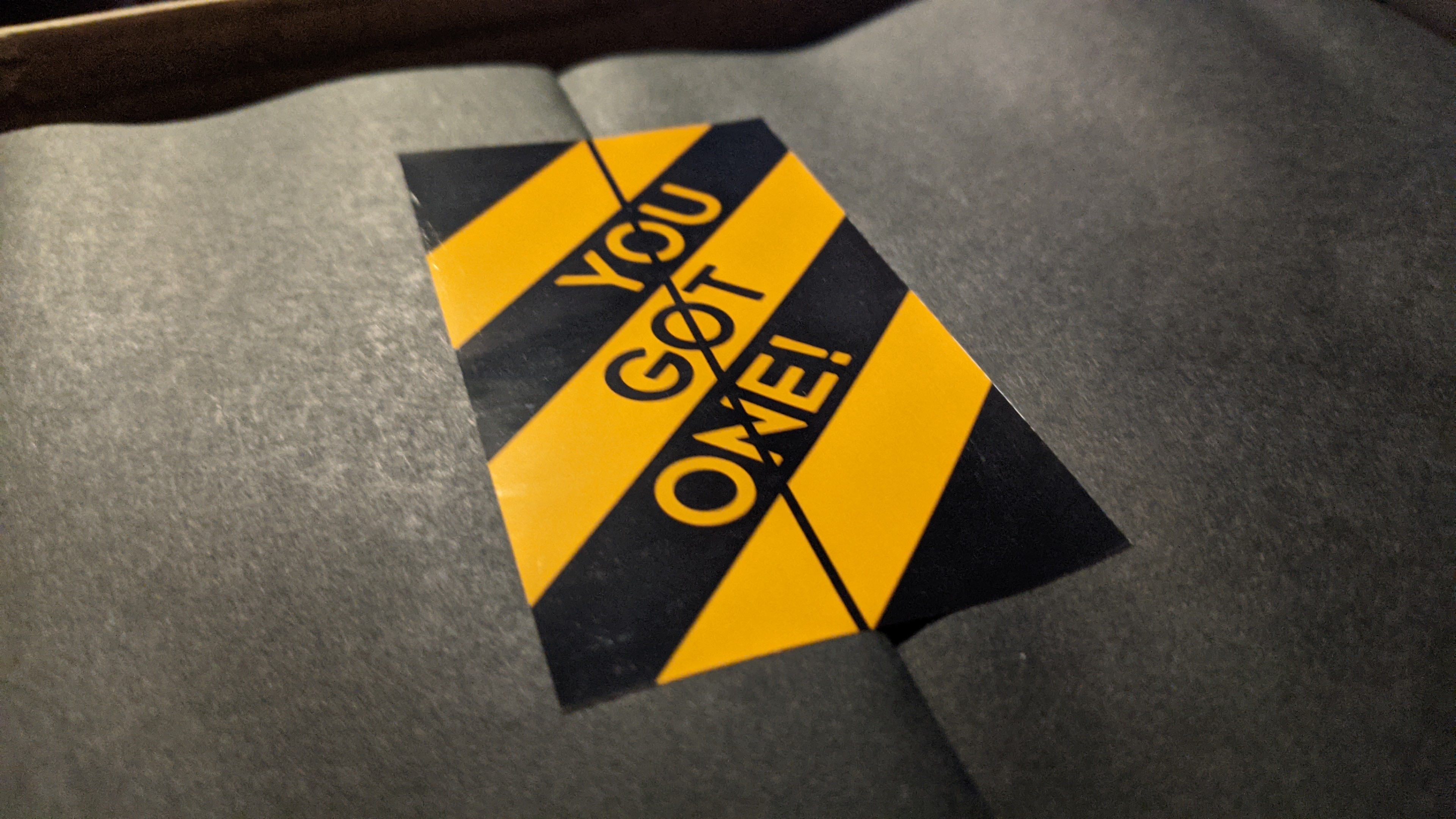
Nice attention to detail on the packing.
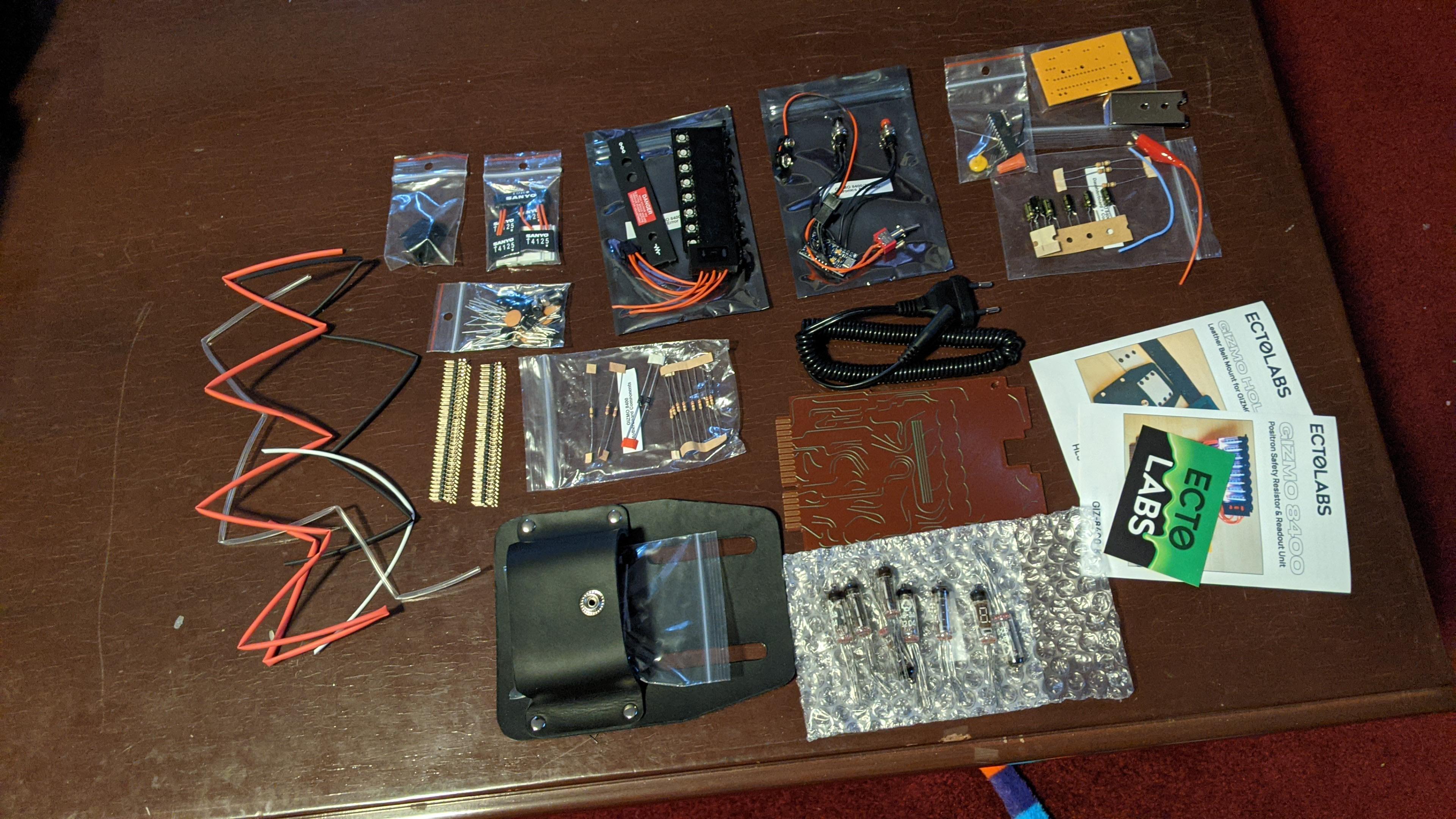
Here’s the full spread of everything. Their kit is basically totally end-to-end, complete replica, minus a battery.
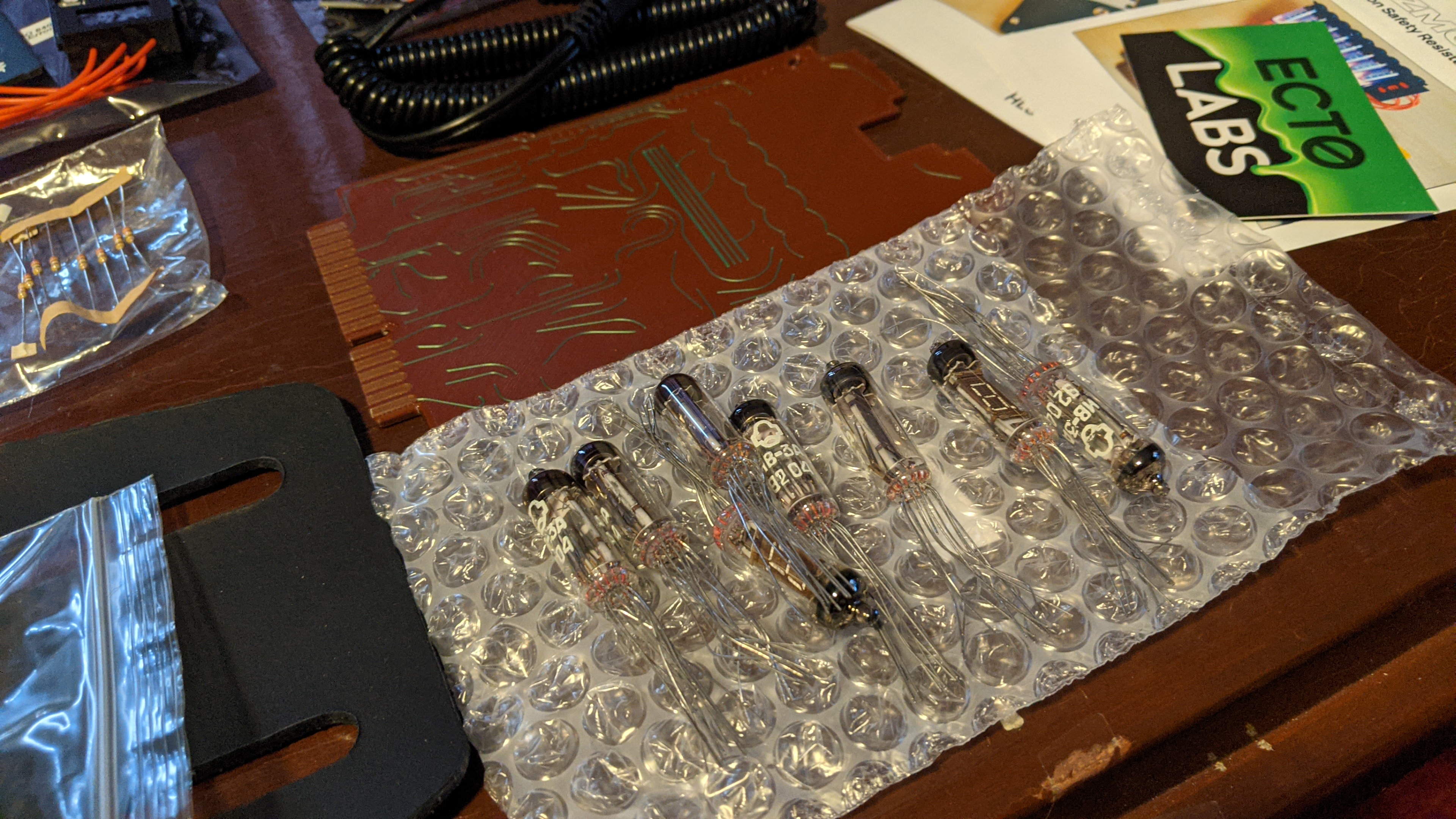
Included VFDs. This is where some customization might happen. The kit simply uses LED backlighting on them. I might do something… more creative… You can also see the main board behind it. It’s 3D printed, but very good quality, with a really nice surface finishing process to make it super smooth.
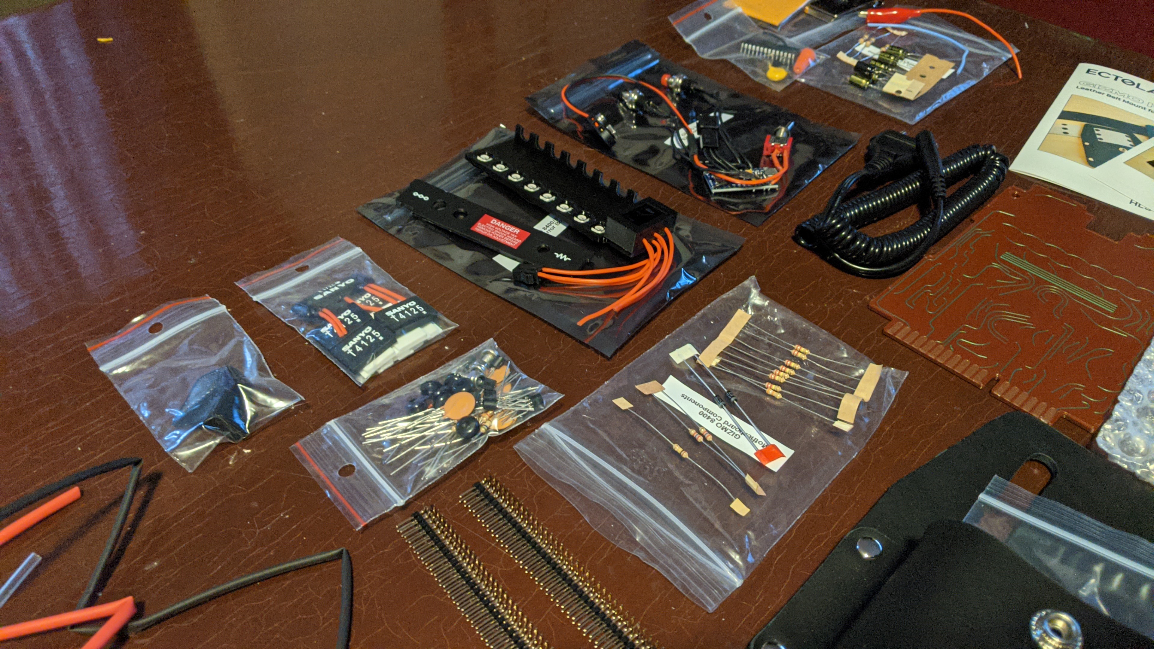
Just a bunch of bits and bobs. It’s worth noting, this is a NO SOLDER kit. Everything is just hot glued to apply it.
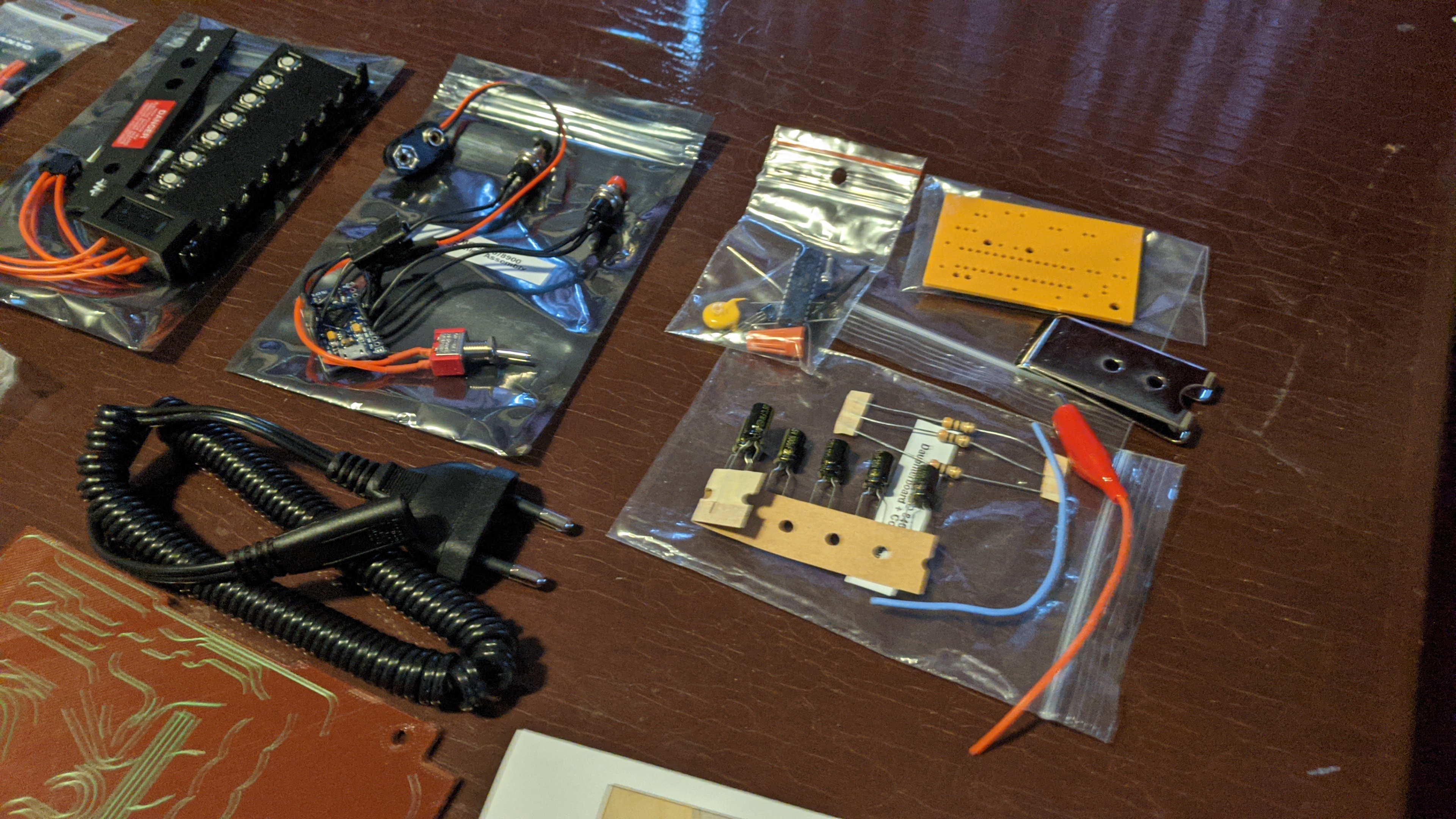
Daughter board bits and bobs. You can also see the actual electronics (connected to the Arduino). I may end up playing with this to swap in a rechargeable LiPo instead of the 9V maybe. Need to take a closer look at the setup to be sure.

More to come soon!

Ace :+1: Looking forward to seeing how you get on!
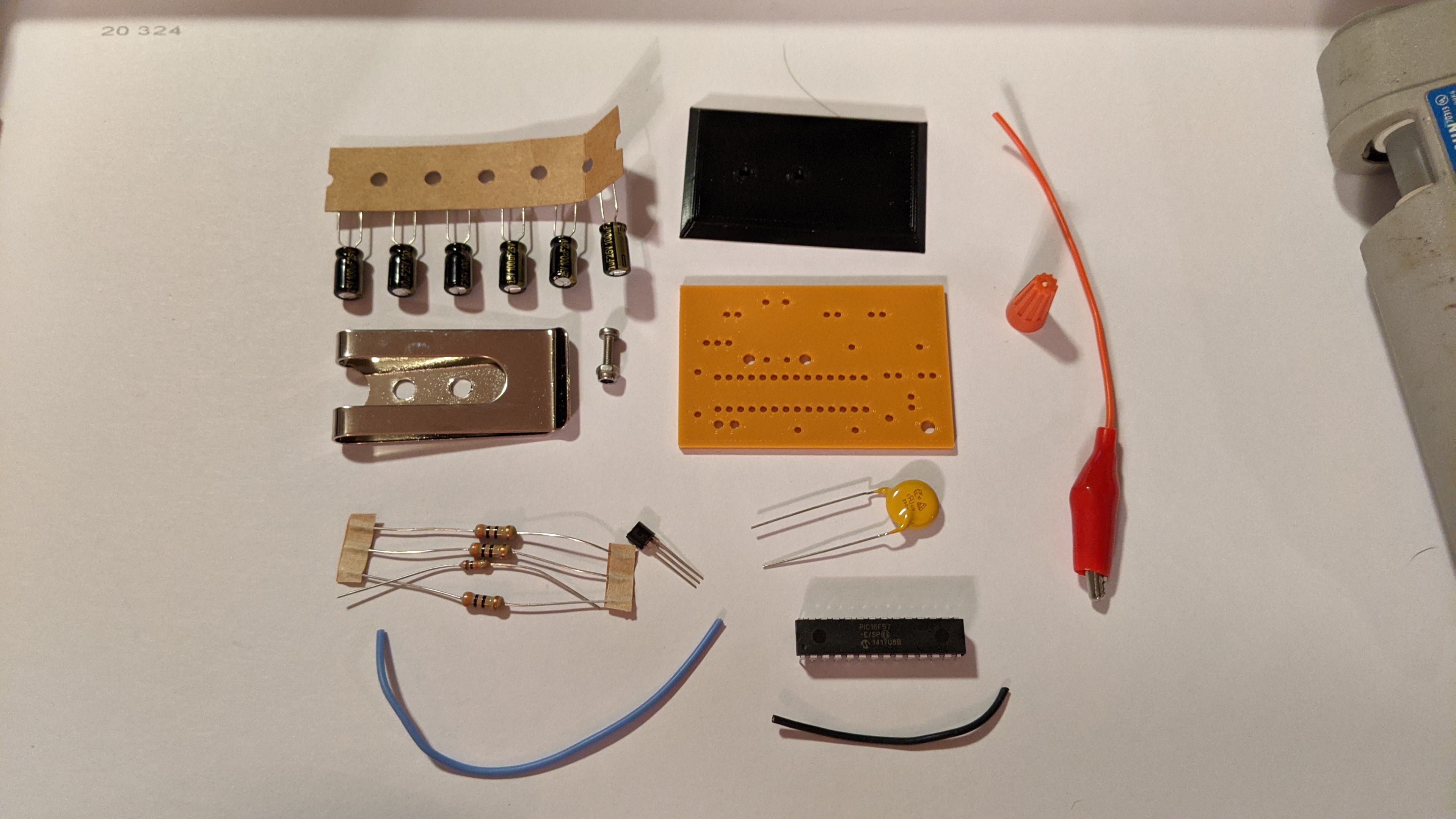
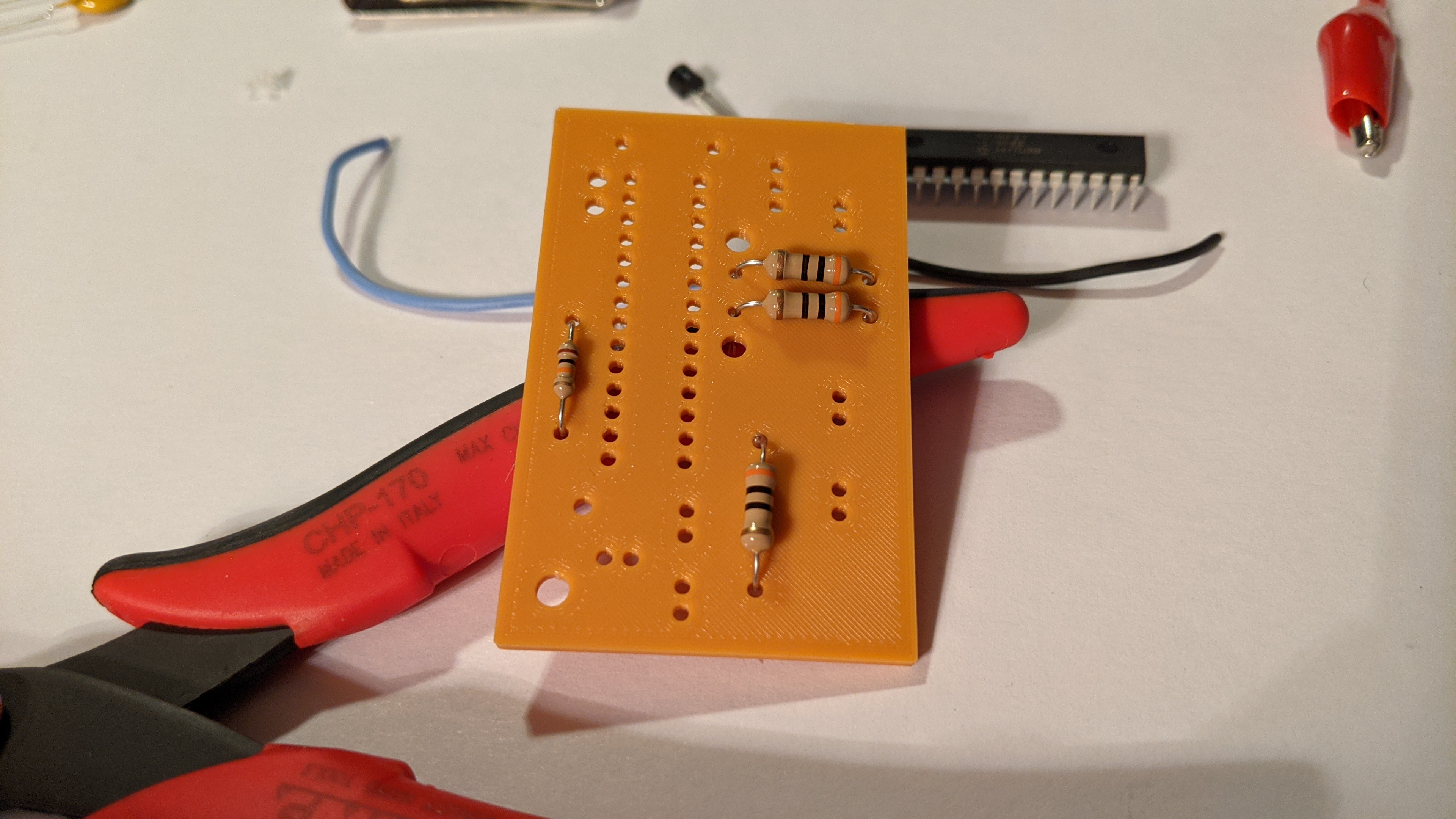
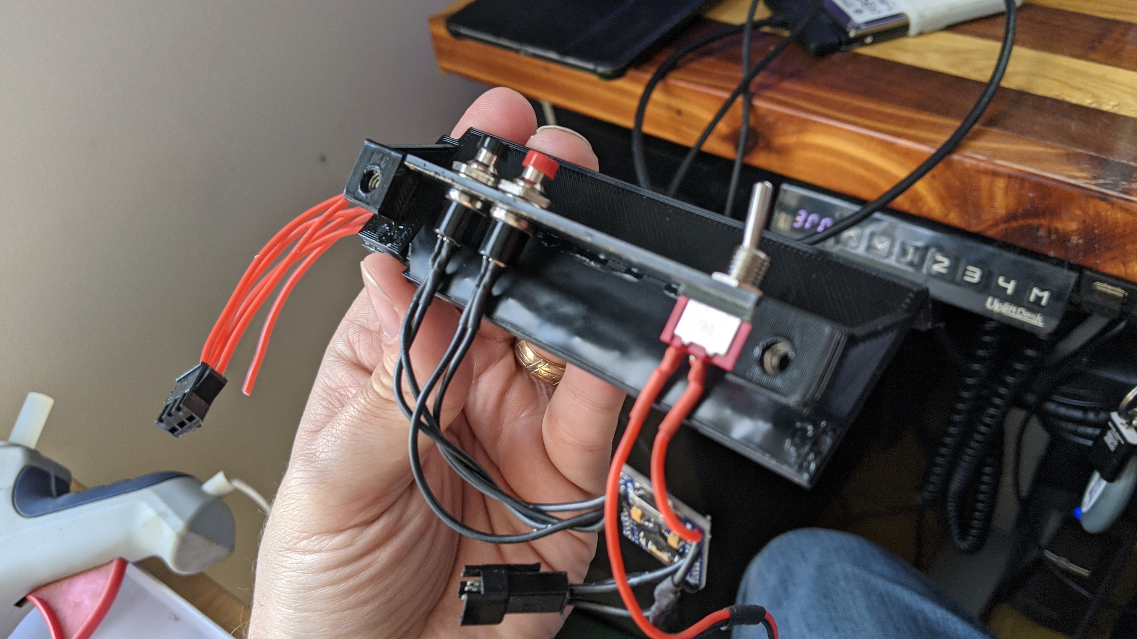
Sorry! It took a while to get started on this. Had to get some time and track down my glue gun. But we’re off and running! The daughter board assembly is now complete!

This is the spread of stuff for the daughter board assembly. Admittedly, this is gonna be super fast compared to the main board.

The first pieces in place!

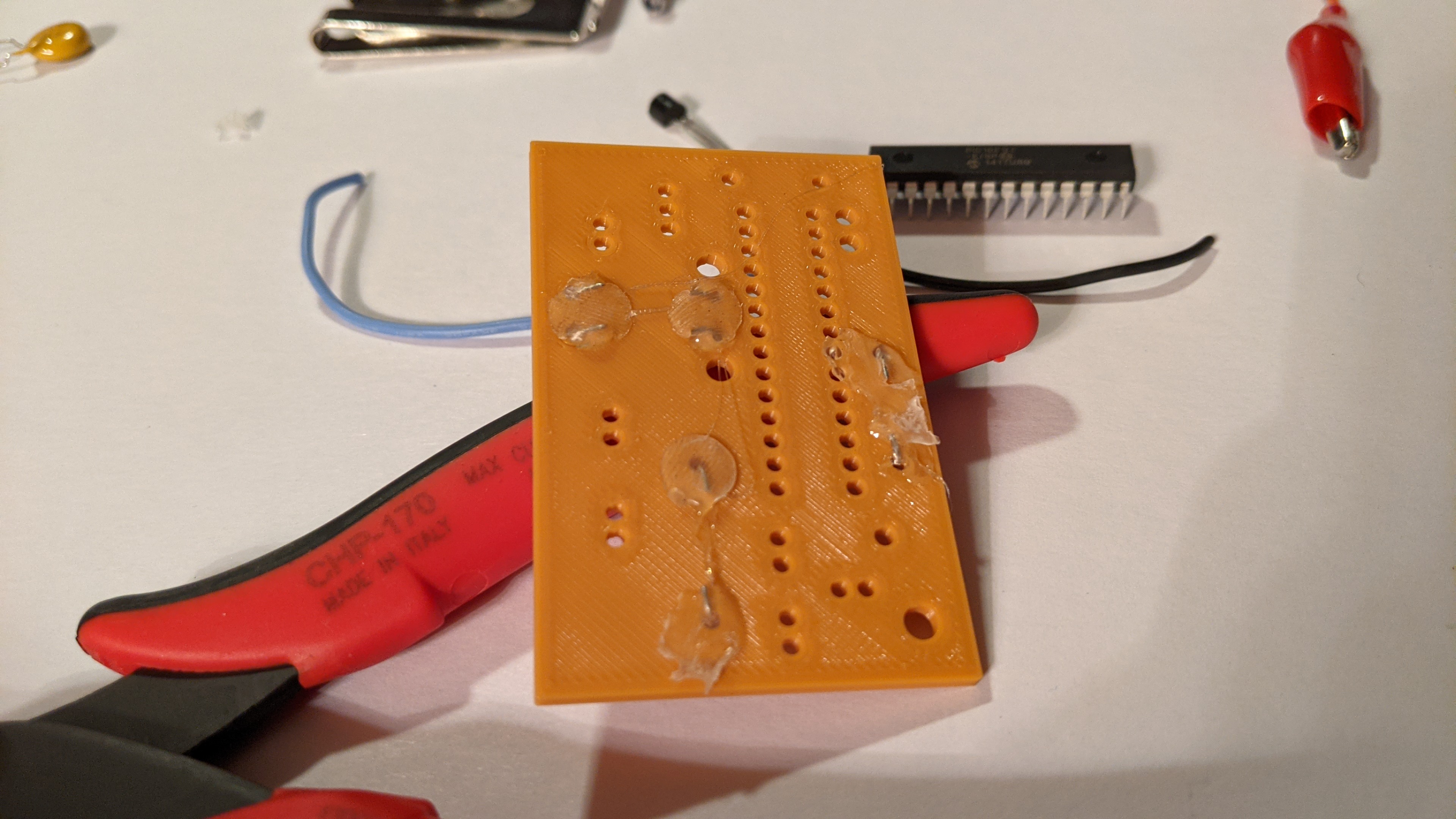
“Soldering.” Make sure you have a good set of precision snips to trip the leads on the parts, you’ll thank yourself later. As the glue cools, I also press down on it to flatten it out some.

No need for more process pics here, really. This is the completed board, everything glued in place. A little extra superglue helps the caps and wires hold in place.

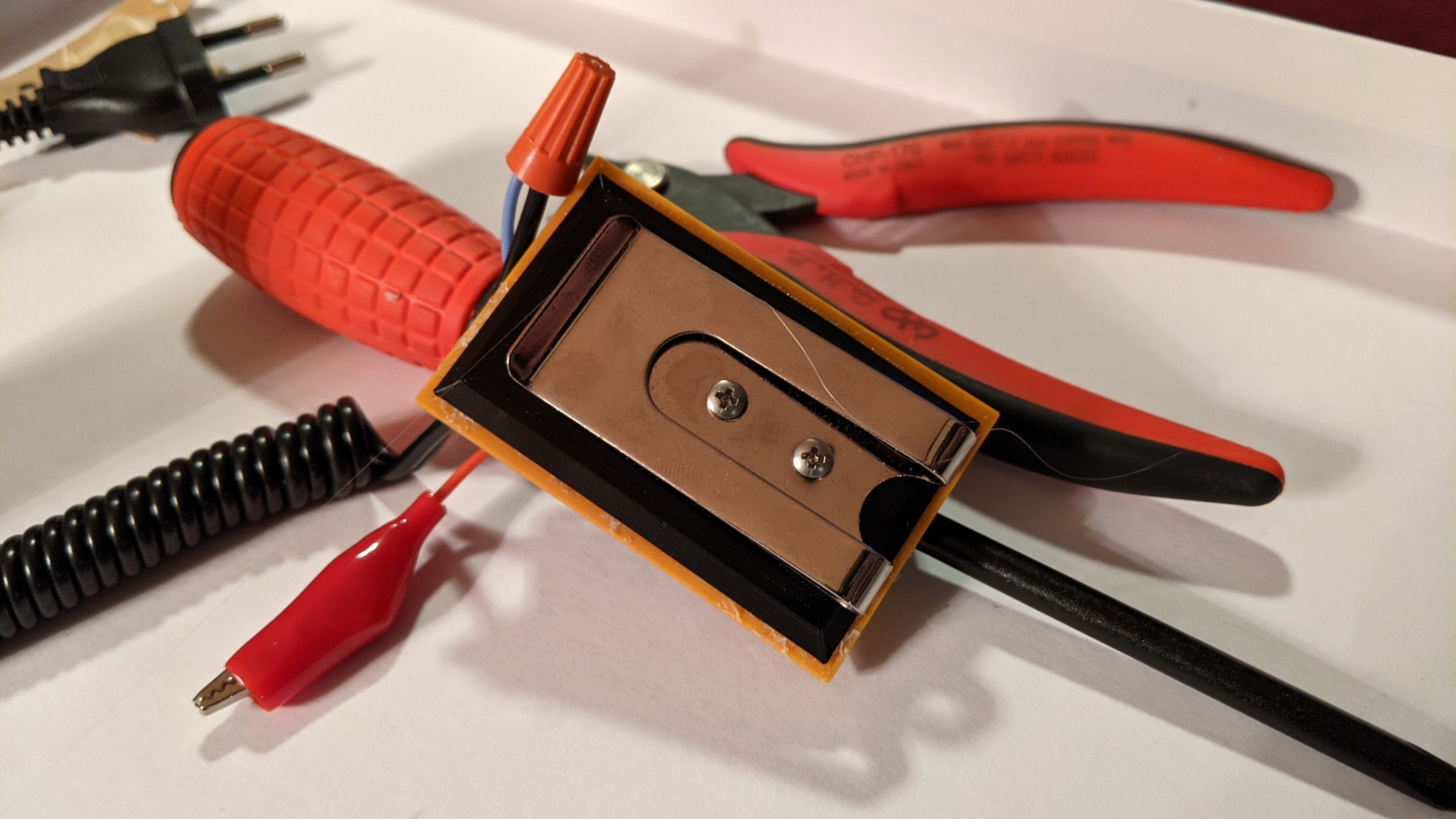
Piece of advice, try to glue the wire ends pointed INWARD on the board. Keep things away from the edges, including glue. The black backing plate is a touch on the small side, and there’s not much vertical depth to it. You’ll have trouble placing it though if you get near those borders, and it’s hard to avoid it.

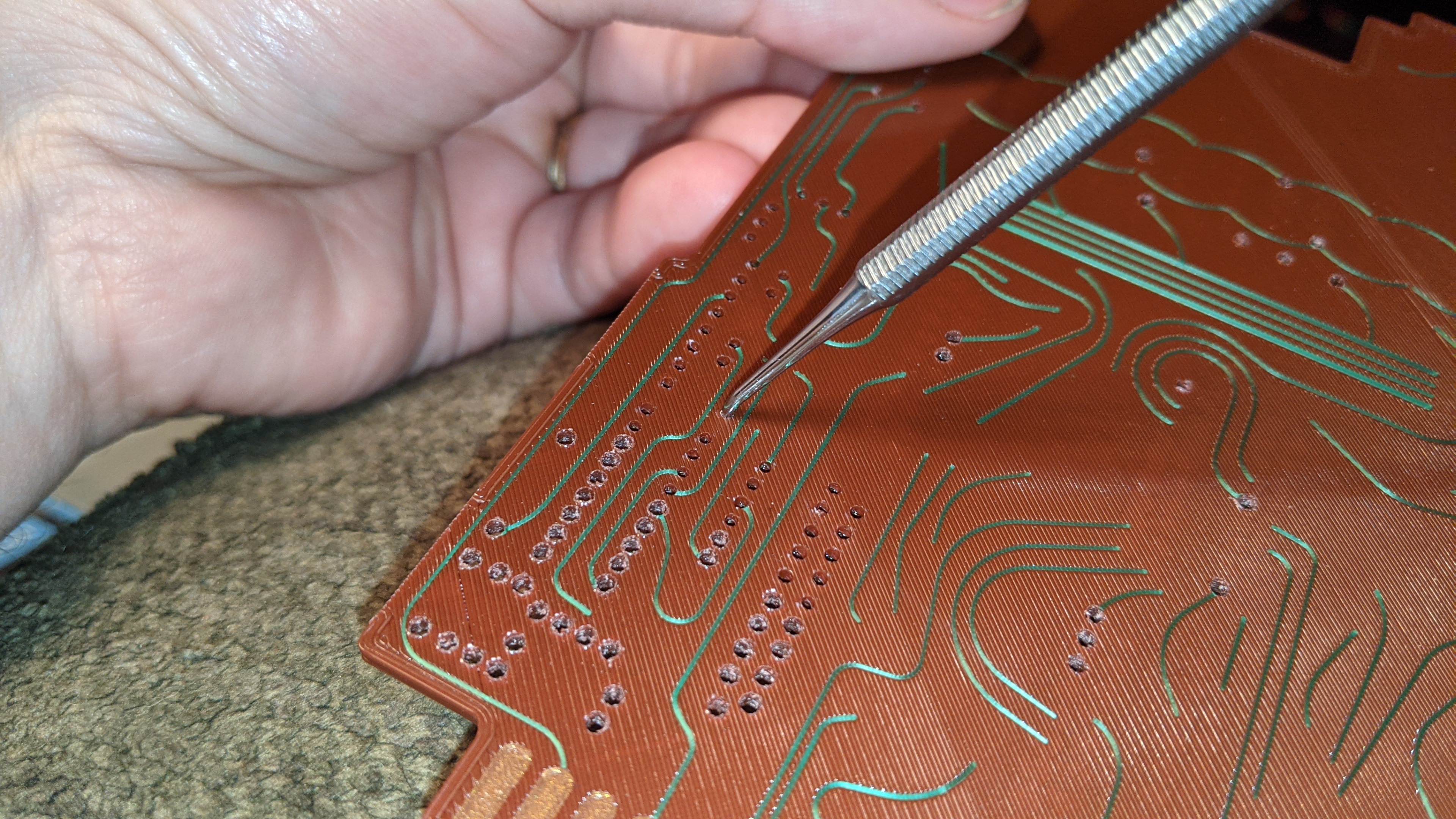
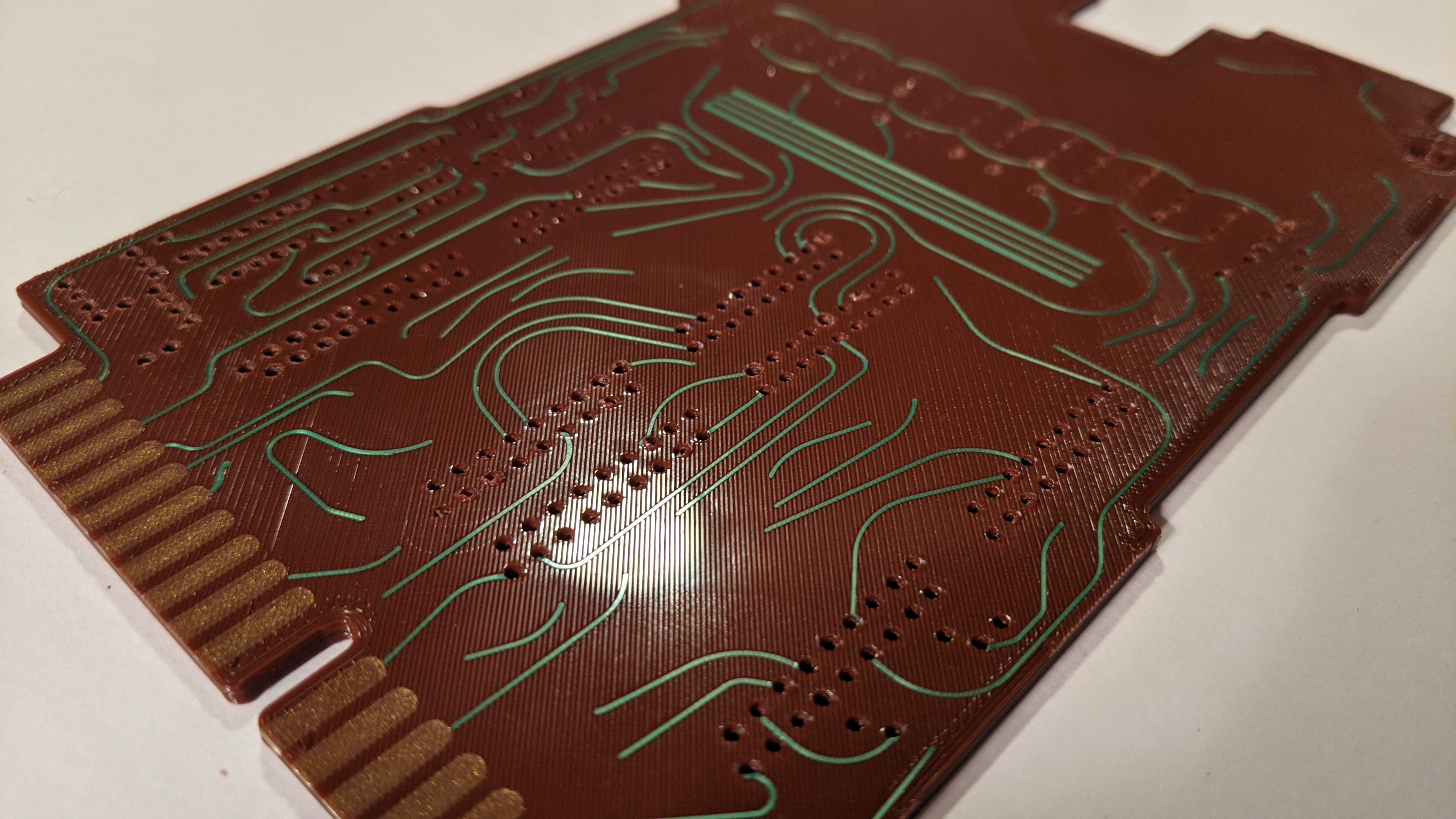
The main circuit board comes with the component holes printed, but coated by the top layer, so you need to punch them. I started with a small, precision phillips screwdriver at first. It worked, but was really slow. A dental pick made it much faster work.

But man… so… many… holes. I did this over two sittings. Had to give my thumb a break.

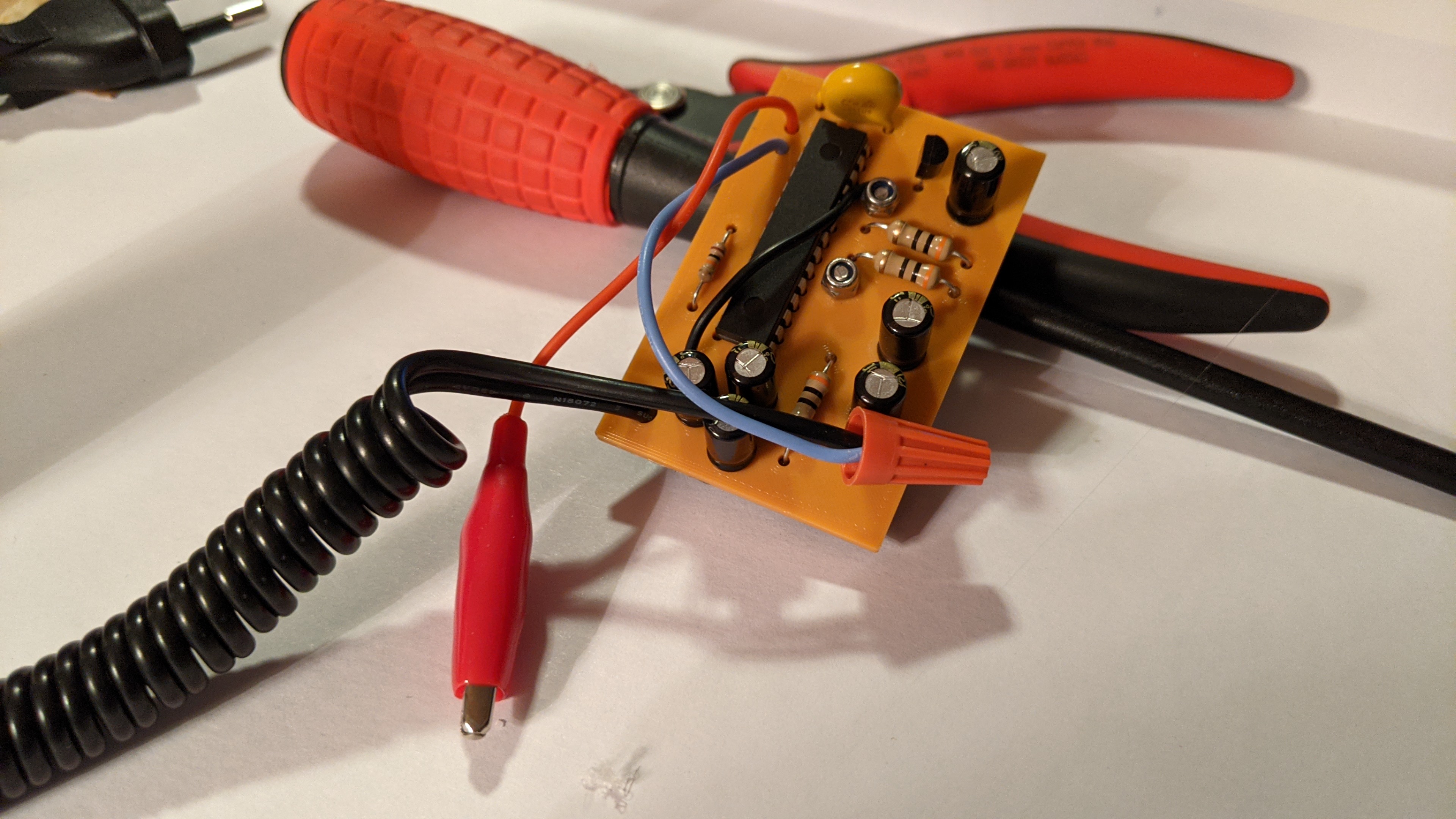
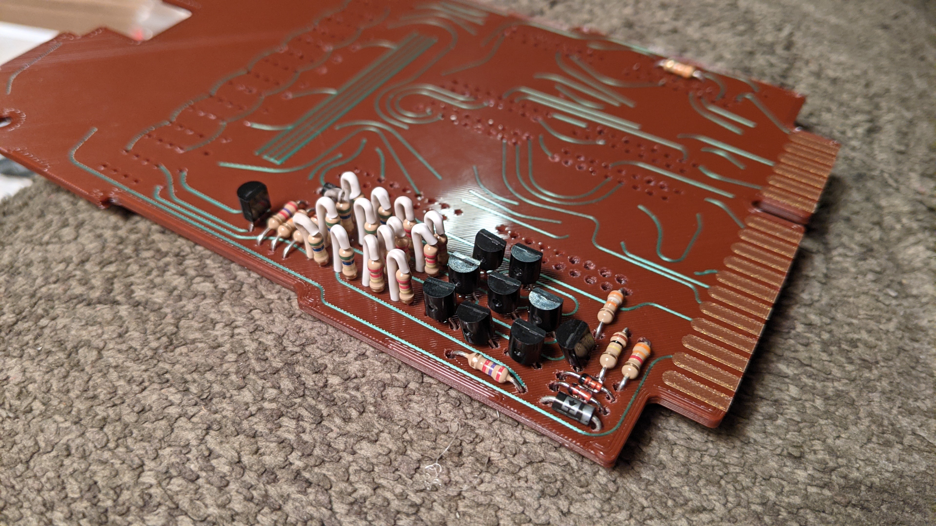
First batch of small parts installed. This doesn’t go much differently from the daughter board.

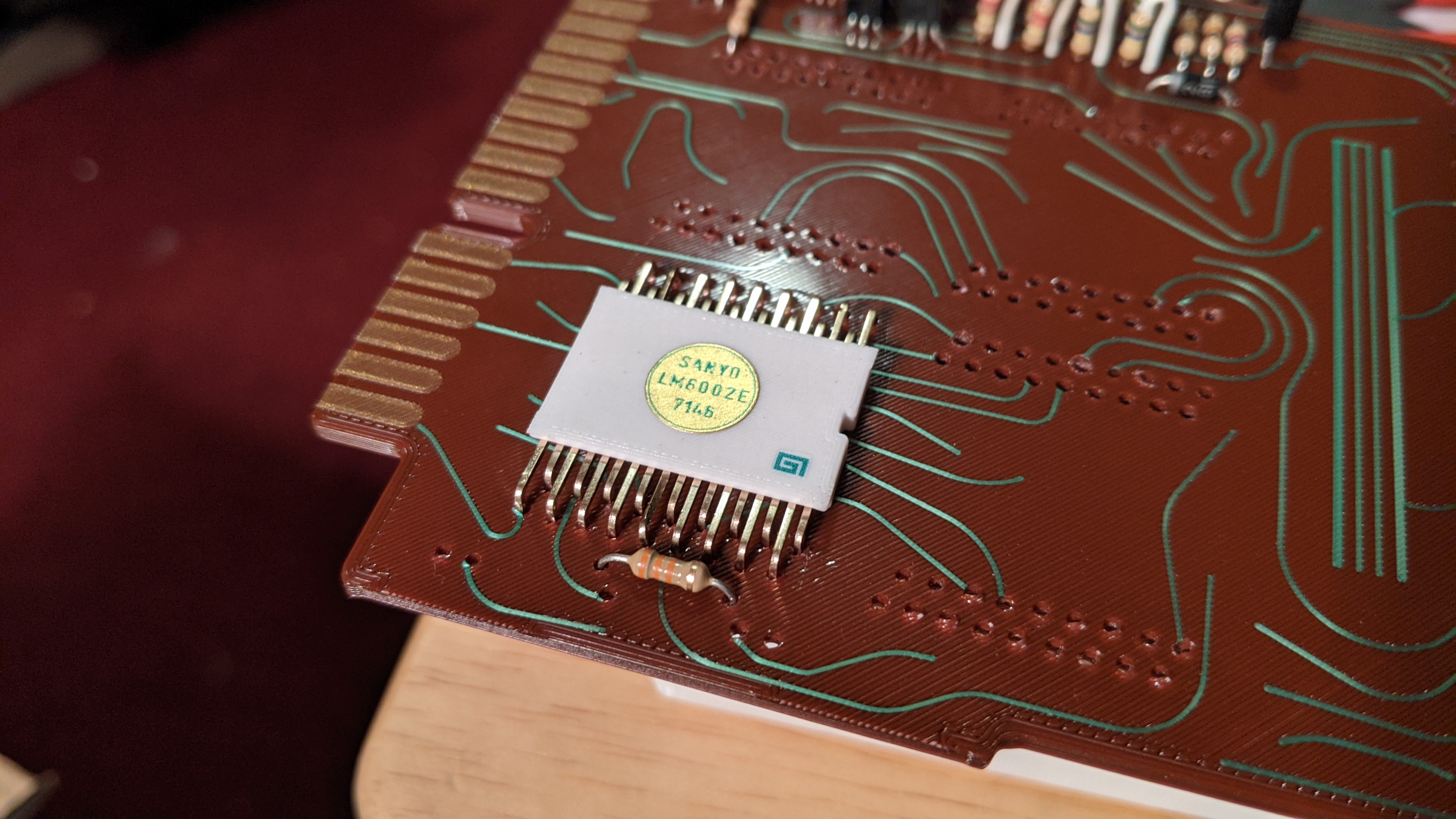
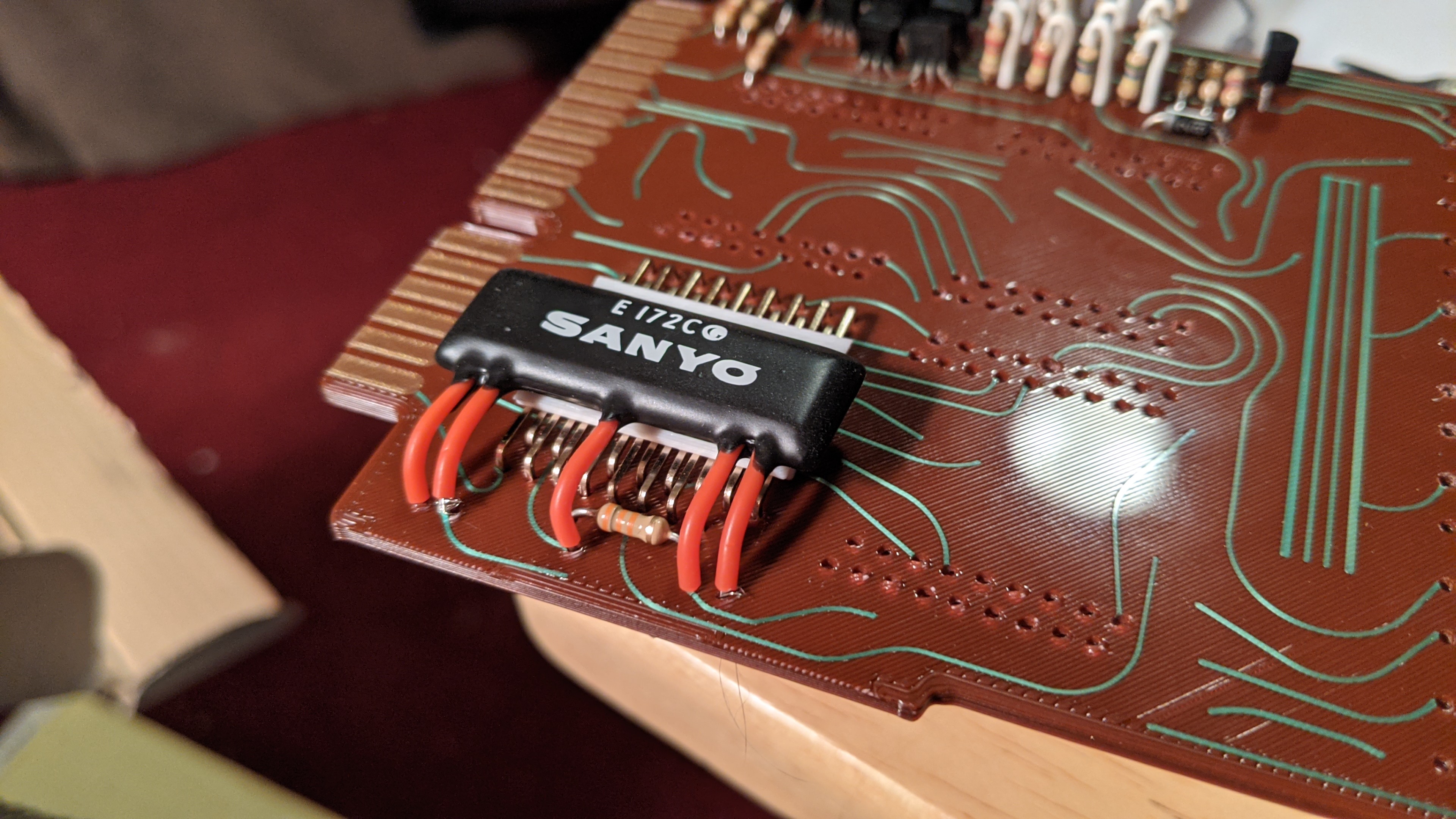
I wanted to test out one of the main chips. Be sure to test fit a few of the pins as you go. If the pins are a hair long, try making the holes a touch bigger. If you need to be more aggressive, trim the flared ends off the back end that goes into the chip so they sit deeper. This is easier if you leave them on the stick and just take half a millimeter or so off each one.

Okay, so I went past test fitting it and mounted it with the additional capacitor(?) on top.

Here it is! The IT’S ALIVE update!

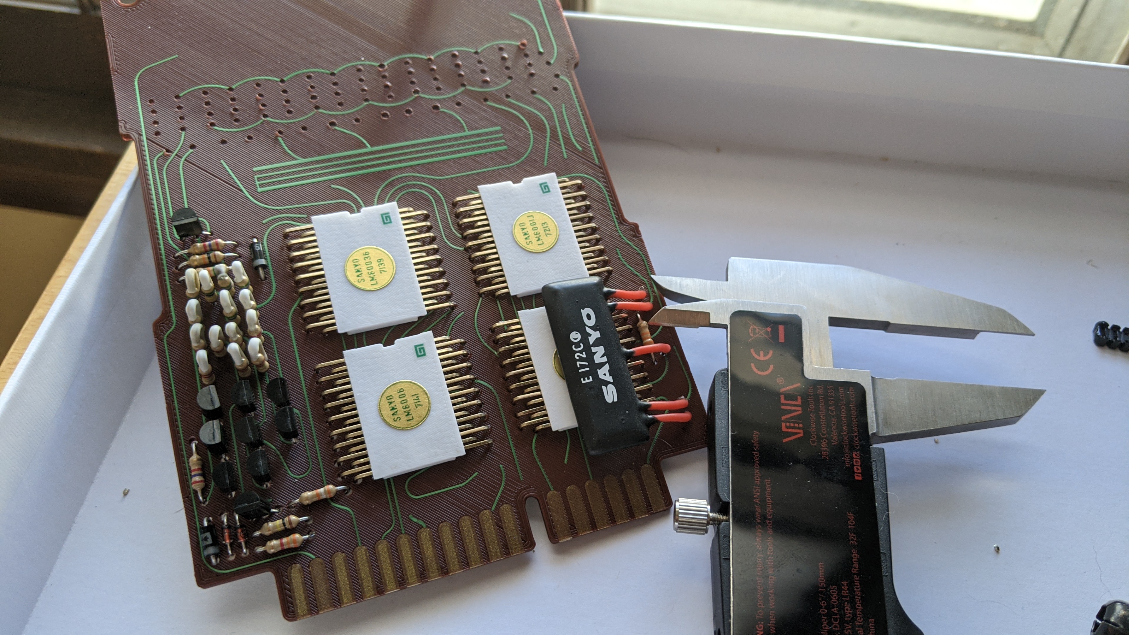
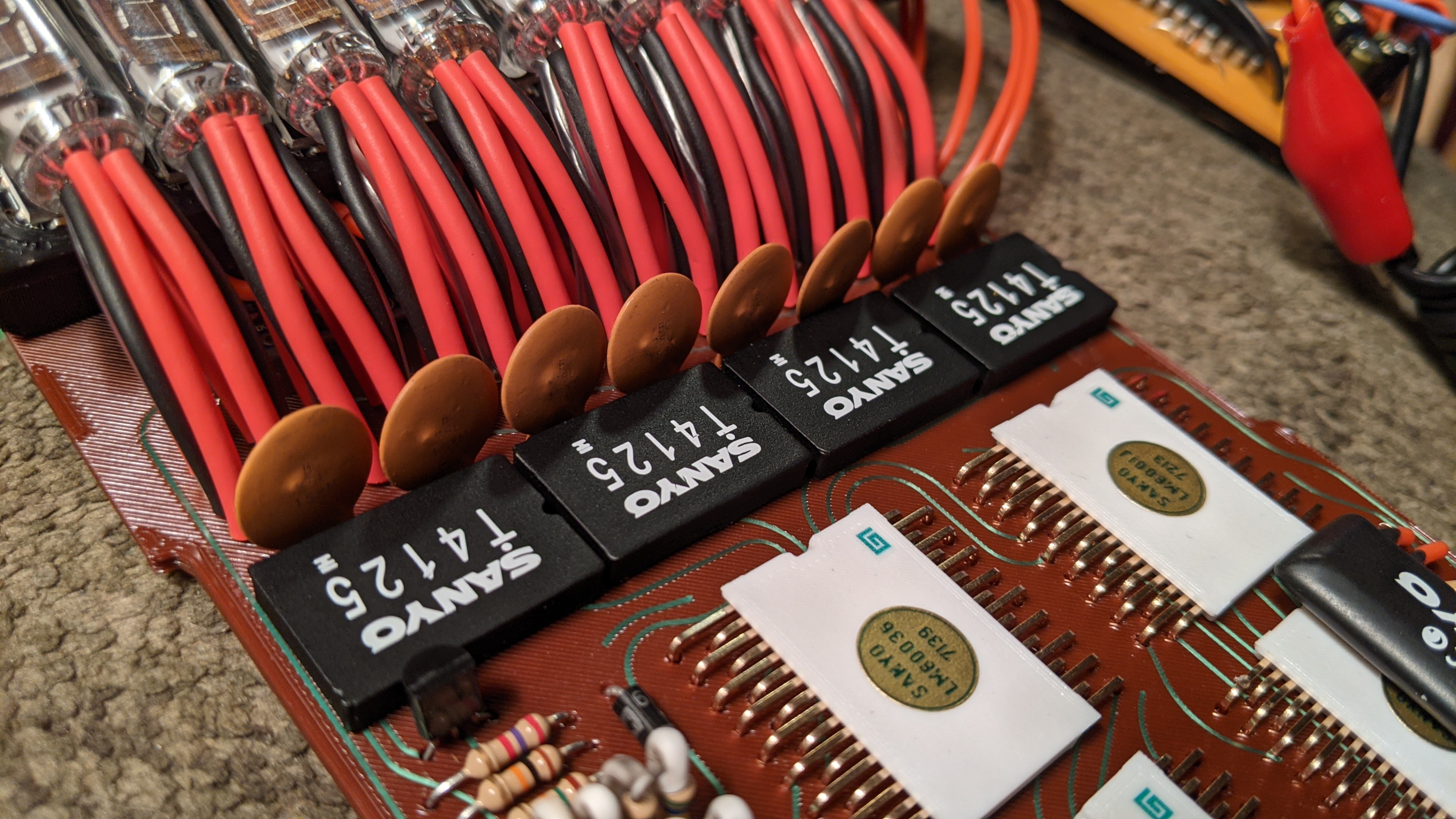
Here are the four main chips done and mounted. These little guys are tedious.

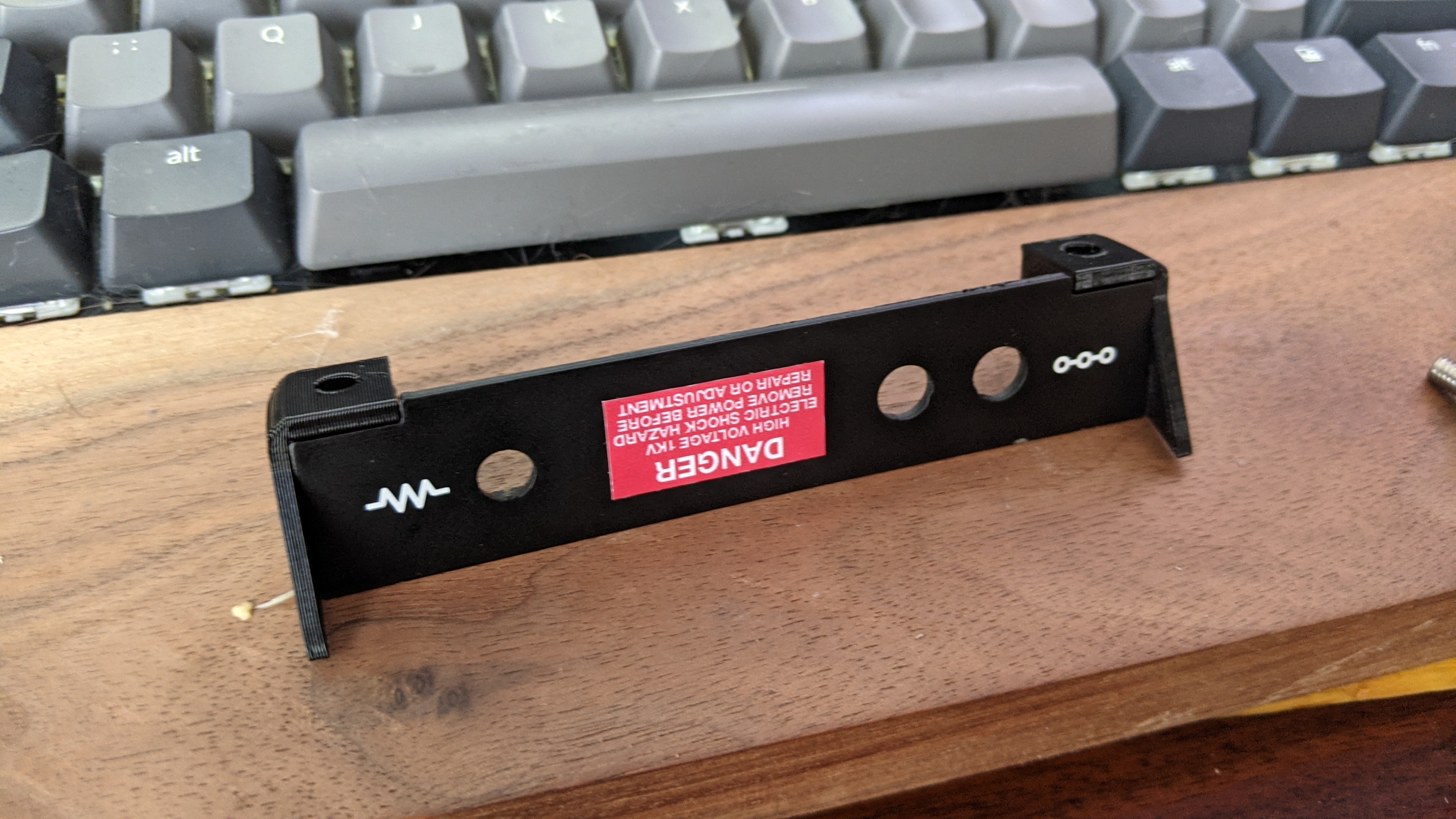
Starting assembly on the nixie rack. Not sure if the sticker is screen accurate, but it’s a nice touch if not.

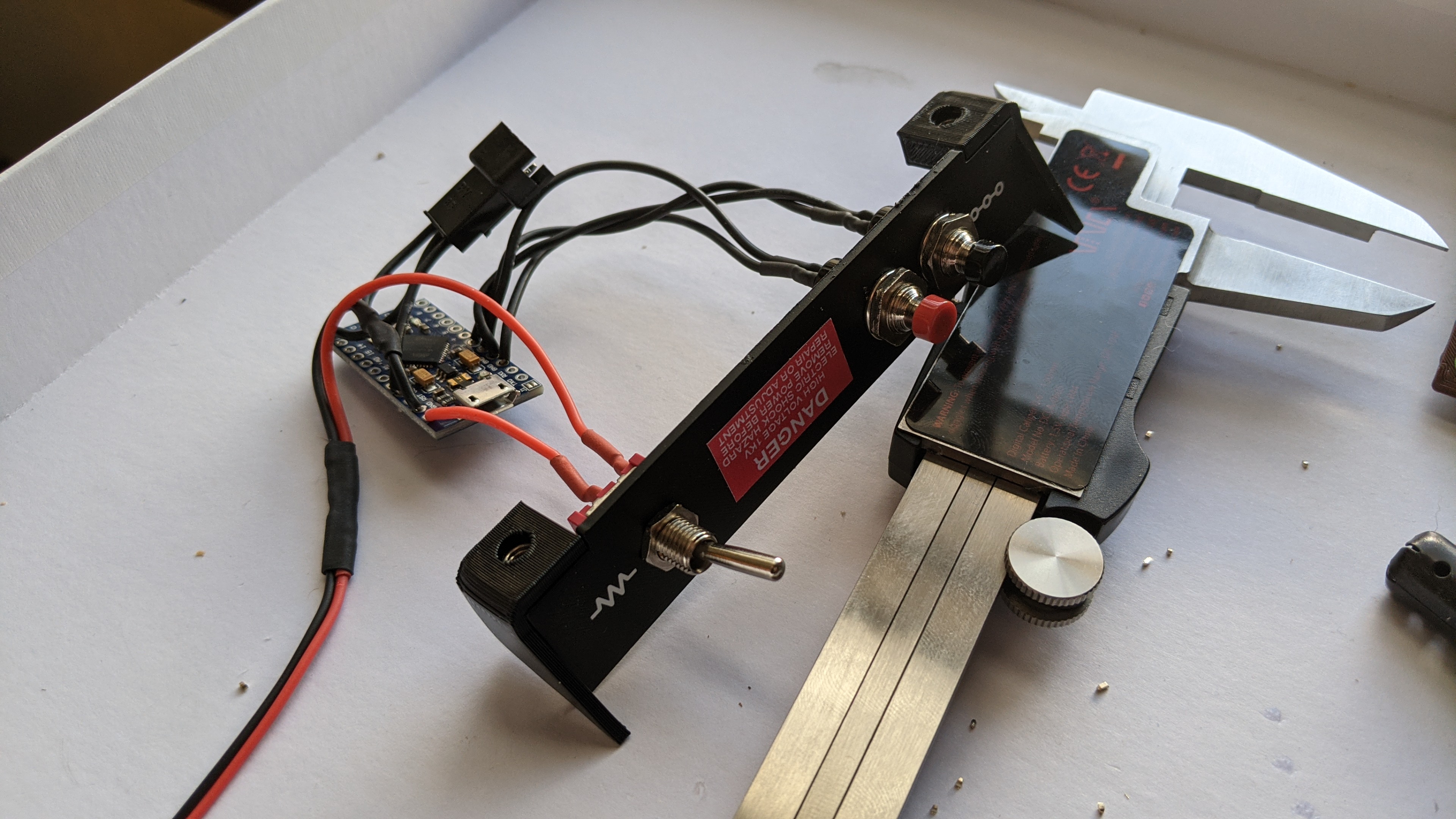
Mounting the real electronics to the bracket.

Electronics from the back. This stuff is all pre-wired, so it’s just a matter of screwing them in.

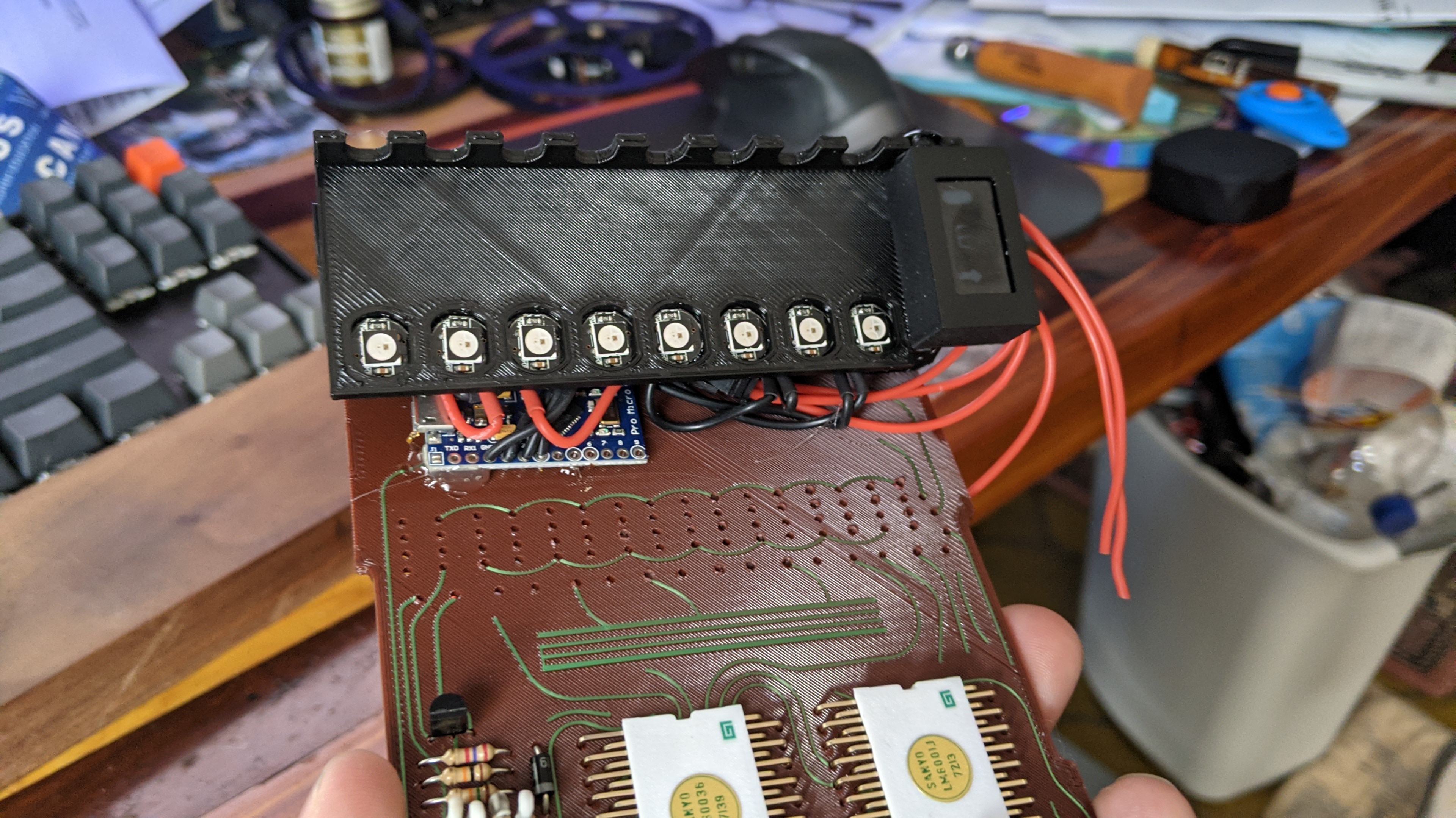
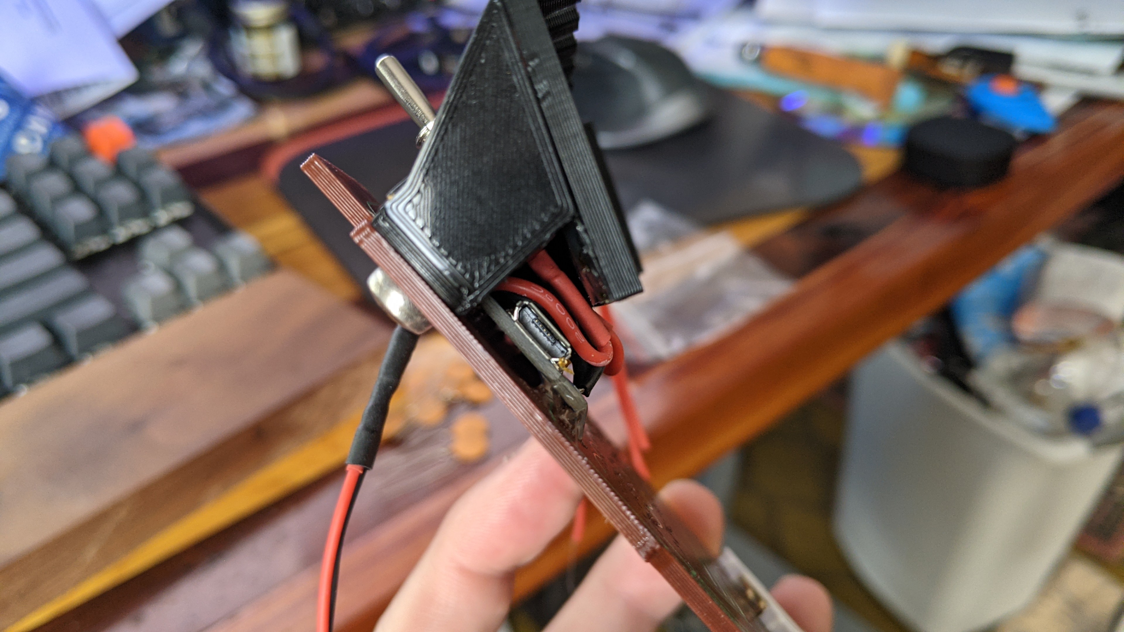
Bracket mounted to the main board. A little hot glue holds the Arduino in place. Don’t worry that you can see it now, you won’t soon.

I did take care here to make sure the USB port is still accessible on the Arduino. I might get half a mind down the road to custom program a light sequence in later, so I want to be able to plug it in.

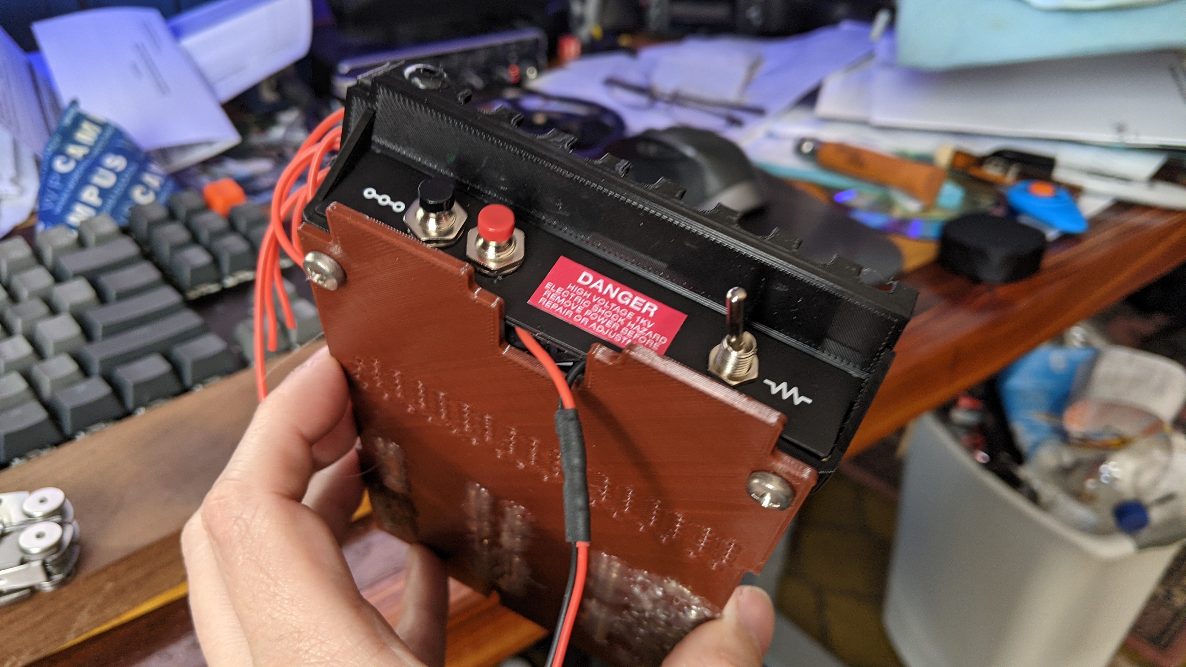
Top view of the controls installed.

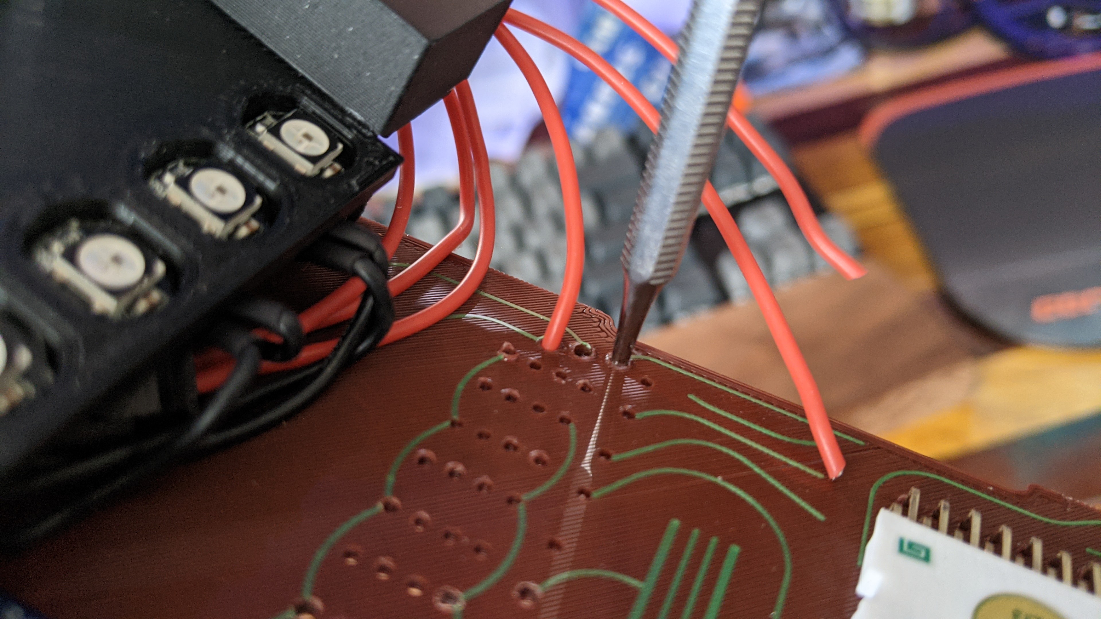
Rather than stripping these wires to thread them through the board, I discovered that I could use the taper of the dental pick to widen the holes just enough for the whole wire to nicely fit through.

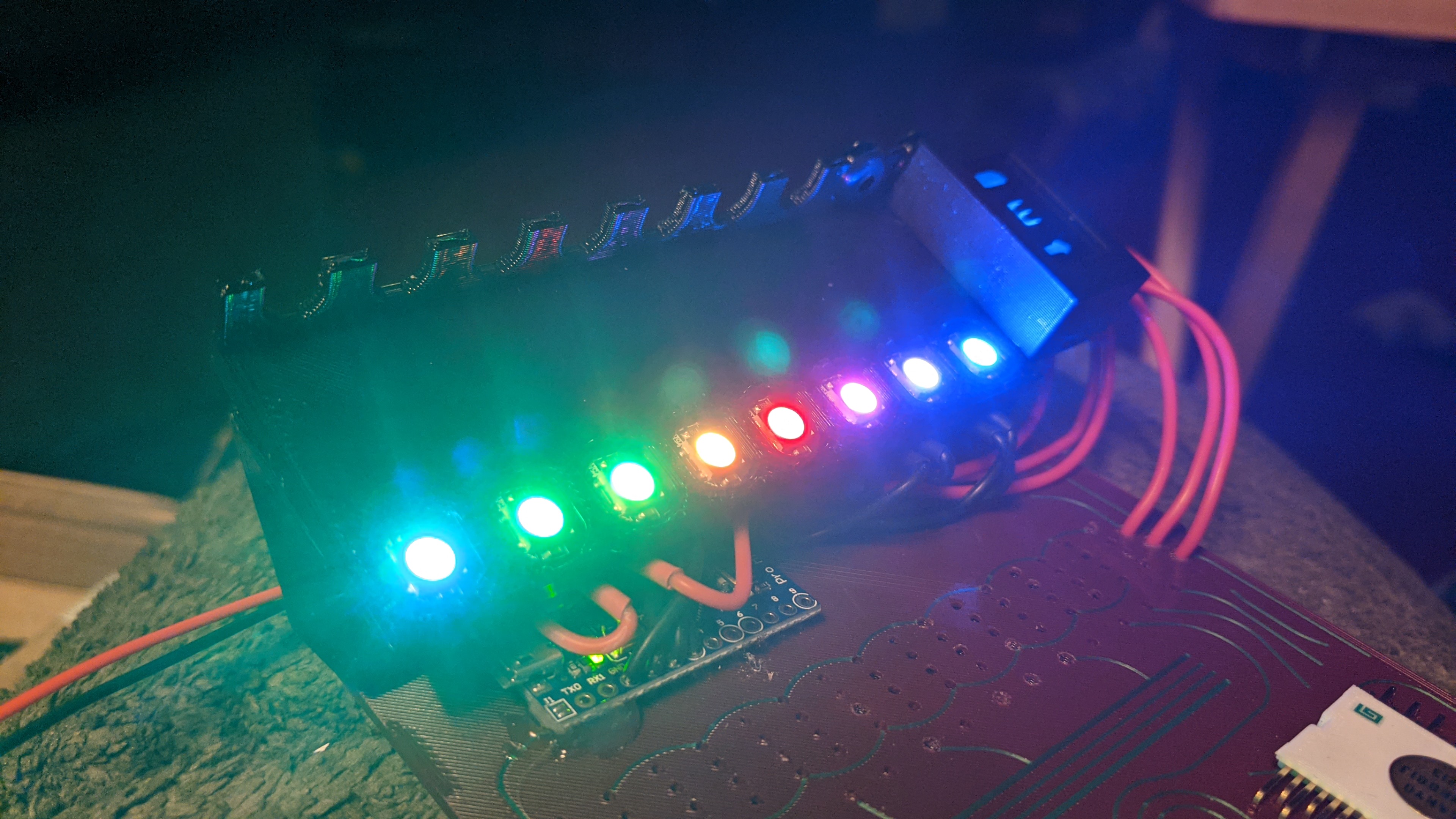
Gotta give everything a proper test before going any farther. Just in case, you know? Plus, I just couldn’t wait.

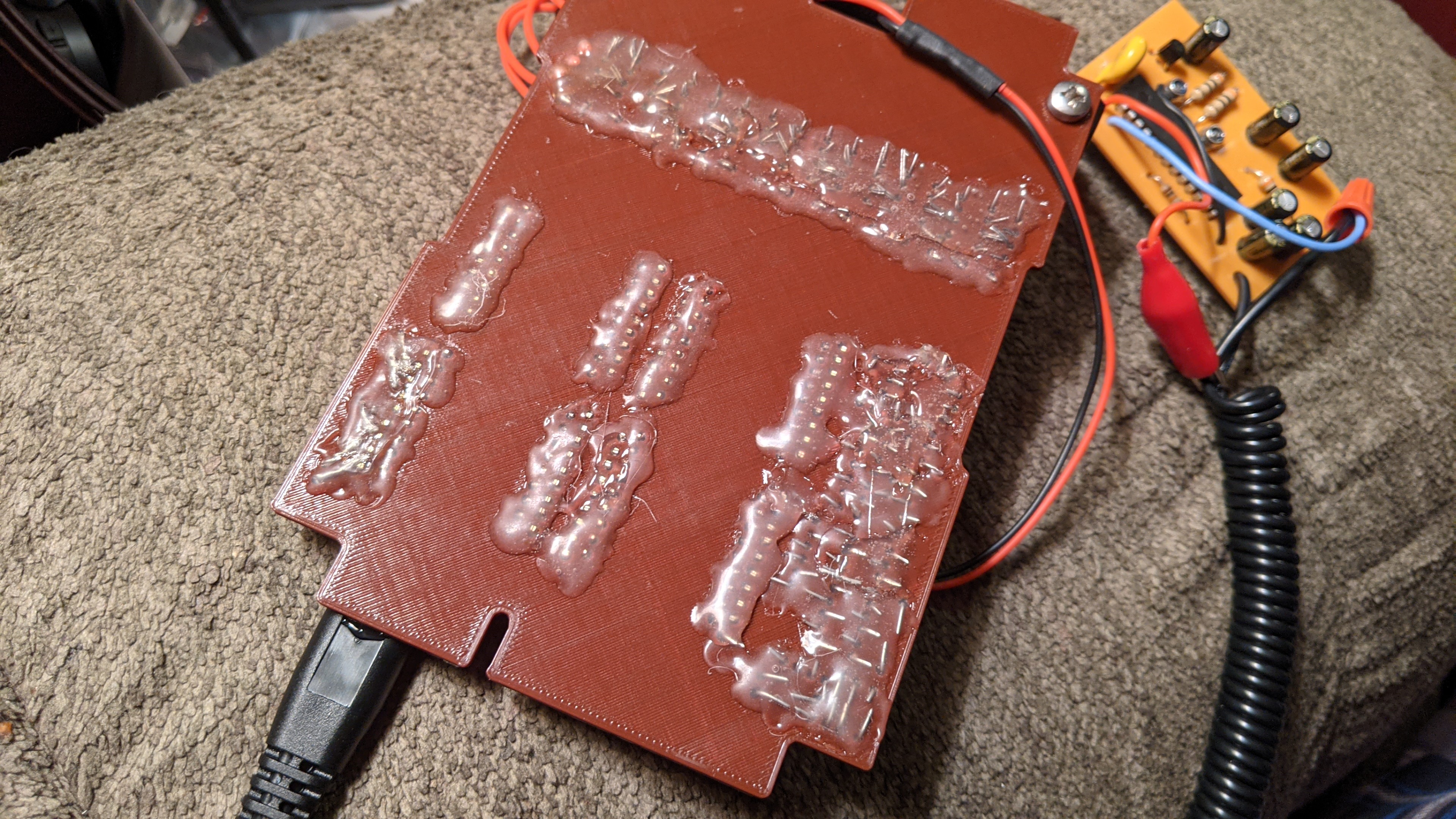
A look at my glue job from the back of the main board. It came out pretty clean. You might notice the top glue indicating I’ve got all the nixies mounted. I was in the zone with those, as they’re tedious, too, and apparently forgot to take progress pics on them.

Front top. As I mentioned, the nixies are all done. The combining, sleeving, and threading of all those tube leads took a while and I guess I just zoned out on photos. Top chips are just superglued in place. You just have to eyeball it a little using traces as guides. EctoLabs, if you see this, adding some registration to the print models would make aligning those super easy.

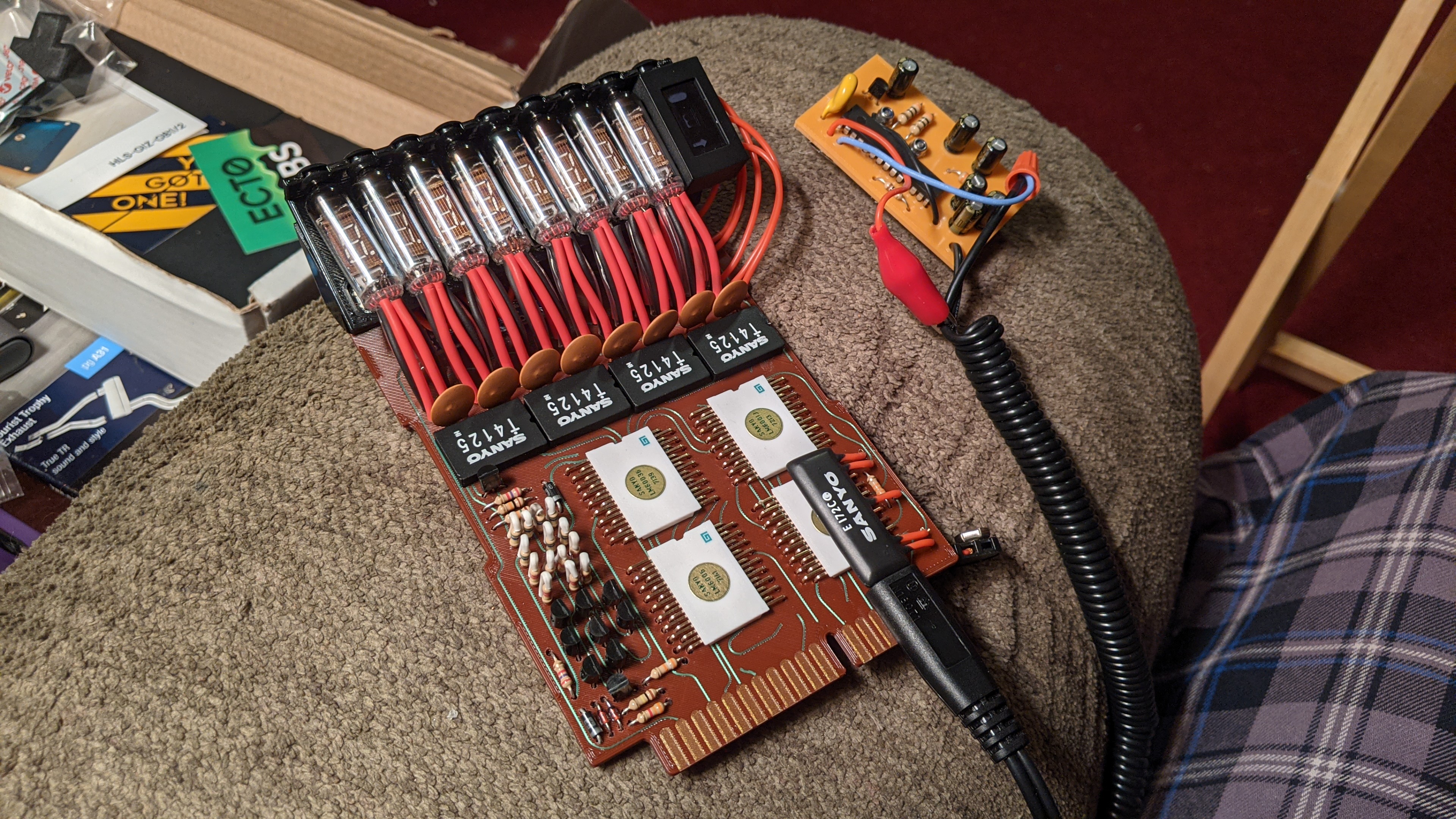
The whole assembly… DONE! It’s very satisfying to see and hold this way. Very happy with the build.

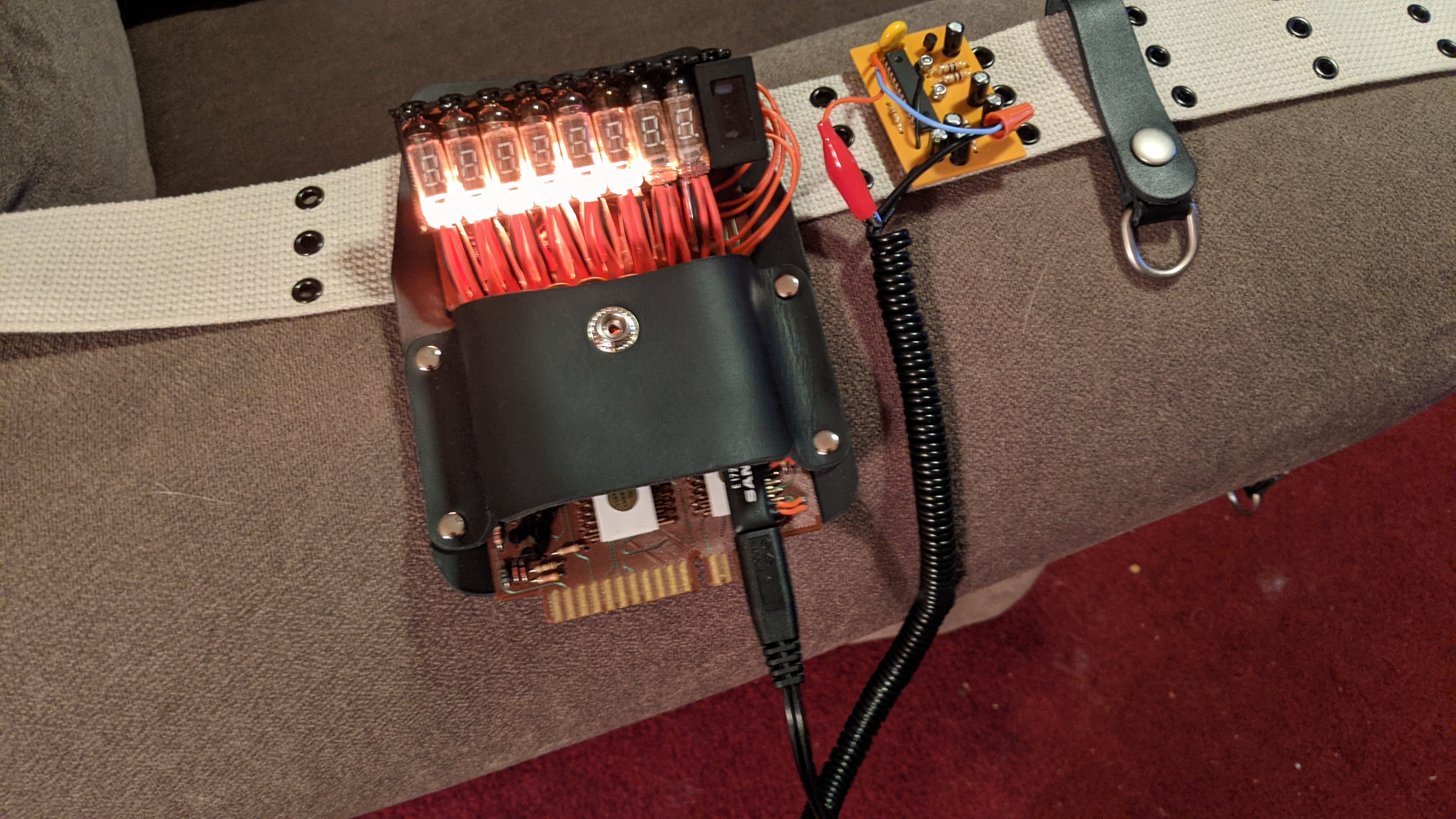
And a shot on the belt for good measure. It looks really great all together, with some light action happening. My jumpsuit is still on order, so I’ll get a better glamour shot down the road.

Any questions I can answer for anyone? Feel free to ask!