Fitzhume - Proton Pack Build

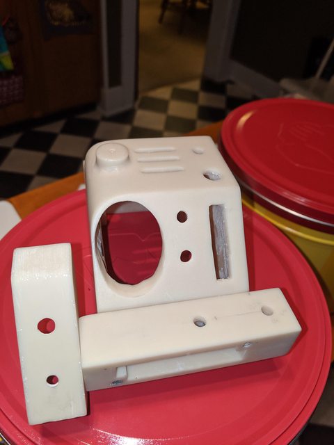
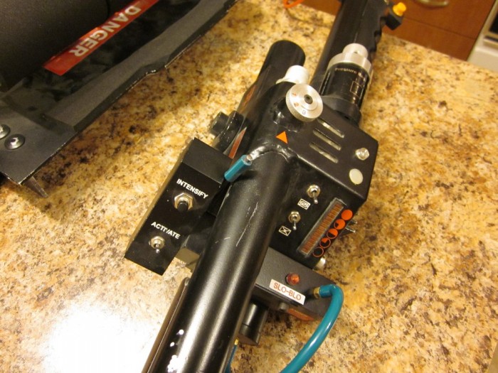
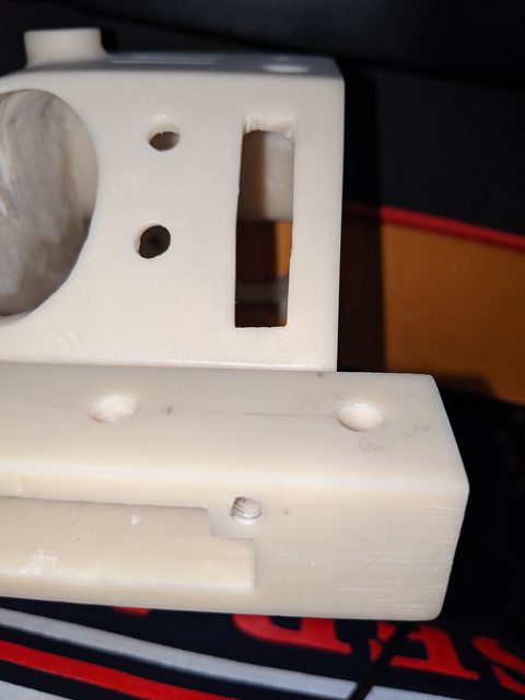
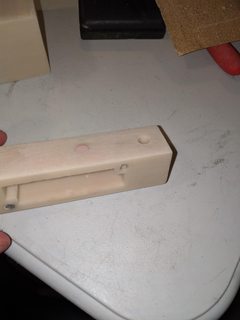
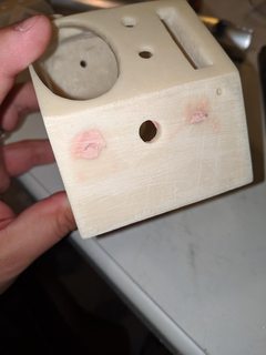
I don’t mean to come off as dickish or anything: your slo-blo light hole looks very out of place compared to what my benofkent hole placement is. It should line up right behind the bar graph if I’m not mistaken?

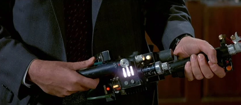
I’m using Filandrius’ build to help reference my current TC build, here’s a pic from his thread:

Just wanted to point it out before you can’t patch/paint without great difficulty. Again, not trying to be a jerk — sorry!

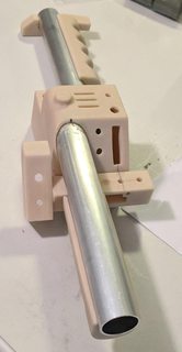
I do have the hole in the trigger box to the rear box. Others have used bondo to attach the handle to the aluminum pipe. Is there a better option to attach the handles to the barrel and rear aluminum pipe?

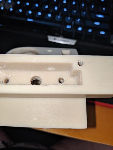
Alleyradb, please don’t apologize, I value people’s opinions. When looking in the rear box, I thought that the bolt used to hold the rear box to the gun box may get in the way of that light. Now, if I were to make a hole for the Slo-Blo just below the bar graph, it would be going into the solid part of the rear box in the same spot that the bolt is holding the metal plate on the rear box. Other pictures that I have looked at shows that the part of the rear box that extends to the right protrudes the same distance out as much as the heatsink is. Ben had holes that match the trigger box so I don’t think I flipped that rear box the wrong way. I’m not sure how to approach that slo-blo hole now as I don’t mind patching it but I don’t know how I would put that hold there as it would go into the same area as that bolt for the plate. I’m thoroughly confused now.

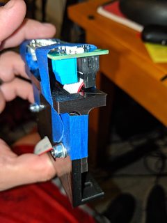
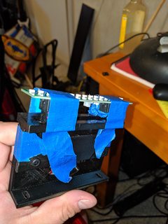
Here is what I see after I pulled it apart:

Any other thoughts? Did I not move the rear box over far enough? Do I have too much space between the trigger box and the gun box? Does the rear box stick out further than the heatsink does? I appreciate all the help and comments from everyone that has posted so far.

I’ve not seen this kit before. The front handle was cast in on mine (Throwing Chicken) so I didn’t need to deal with that.

I can say that the originals were attached with screws/bolts. The rear handle was attached via holes in the first and last finger grooves, presumably by threaded holes in the tube. The front handle was attached “lengthwise” with one screw/bolt going through the front ear and the other through the rear bump, whatever that’s called. You can see these in various reference photos. Whether these methods will work with your kit I don’t know.

After looking at it again this morning, and from the following picture of Egon from GB2, I can see that the rear box protrudes just a bit further than the heatsink. I don’t think I’m off by much though. Still, I probably will have to plug the 2 mounting holes in the gun box too. As for the Slo-Blo hole, have those that used Ben’s resin kit have to cut into that small block where the bolt attaches the metal backplate?

The gap on the left side of the gun should be between 1/8” and 1/4” — the lever is 1/8” brass so it only needs a couple 1/16’s clearance so it isn’t dragging on the side of your trigger box or handle.

I had to drill into the solid part of the rear instrument panel to mount my light. I went in through the end where the trigger box is and drilled through the trigger box entirely, then through the panel wall (I think it was a 1/4” drill bit — it was a bit to match the hole that is large enough to accommodate the plug ends of my electronics) to hollow the area. Then drilled down into the tunnel below from above where the light hole goes. I then used bondo to patch the hole I made on the trigger box. Just be very gentle and slow with those larger bits — I cracked off a corner on my current build while widening a hole and had to bondo the heck out of it.

If you’re worried about drilling or can’t get in though the end piece you can always dremel it out or you can dismount the rear box and cut into it from behind where it attaches to the gun body — this would hide any damage if any was done.

Hope this helps!

This does help except for my initial question about the placement of the slo-blo light cap. Since it sits just above the bolt that holds the rear box plate, does your hole interfere with this bolt at all? Thanks for your response and please know that I don’t get offended easily :slight_smile: I appreciate all feedback and criticism.

With this kit, it was always shown using Bondo to attach the handles, however, I’m going to research on attaching the handles with bolts instead. I do have a tap kit so that shouldn’t be a problem and just countersink the holes in the handles to create a ledge for the bolt to hold on to. Thanks!

Here are a few photos showing how the grips were attached.

Rear grips, two bolts in grooves, one at each edge…

Front grip, two bolts, pinned on each end…

[quote=Fitzhume post_id=4923411 time=1567004555 user_id=15884]This does help except for my initial question about the placement of the slo-blo light cap. Since it sits just above the bolt that holds the rear box plate, does your hole interfere with this bolt at all? Thanks for your response and please know that I don’t get offended easily :slight_smile: I appreciate all feedback and criticism.

[/quote]

To counter that problem, I ended up using button cap socket heads with washers to secure the rear instrument panel to the gun body – which in turn also made for easier routing of my electronics, with less to get potentially caught on when fishing said wires.

EDIT: I just re-read this and realized you meant the screw for attaching the plastic plate. I thought you were referencing the screws for attachment to the gun body – please disregard the above.

If the instrument panel box is in place as you want it, just use a shorter socket head – maybe 1/4" length or possibly something shorter. The plate doesn’t need a lot of threading to hold it in place: you can snip the end of the screw off using End Cutting Pliers. But you should be able to find something relatively short in 8-32 or 6-32 (depending which you are using) that should prevent that.

Worst case scenario: you trim a screw down and get a hand cramp because those hardened screws are hard to snip through!

I plugged the holes tonight with Bondo. Waiting for that to set, sand, and place the rear box again.

It’s been a bit since my last post due to the weekend but I have been working on my pack a little bit. I still haven’t found a way to clean up that lense I botched but I’m going to wait to see how it looks when everything else is in place.

I put some work into filling and re-drilling the holes in the gun box and rear box to line up the Slo-Blo light properly.

After much debate, I decided to take the suggestion to attach the grips with cap bolts which worked well. I did have a little trouble with countersinking the 1st hole but I fixed it using a Dremel bit. My front grip and place for the wand tip button/light is one piece so I was not able to attach the grip as the movie prop does. As for attaching the barrel and rear grip pipe, I used E6000 glue and waiting on that to set up.

The angle of this picture doesn’t show to space well between the grip and the rear box but there is space.

I have received my Clippard elbows and have installed them as well. They look rather sharp once on the pack. I need to get a bit more blue hose for the line tube to the HGA. I may have made the blue tube a bit long from the PPD to the resistor. Does anyone use a blue hose that is somewhat hidden in the split-loom to the HGA?

I will edit this post with pictures of the external pack later tonight. I will be putting the bumper and injector lines later on in the process as I need to work on the internals of the pack and lining up the reflectors to the Cyclotron lenses.

Excellent progress. This build is coming along really well!

In terms of the volume pot, I concur with Bishop that it is entirely a matter of preference. Personally, I really liked installing it on my Spengler plate because it is easy for me to reach while I am wearing my pack, it doesn’t look out of place, it remains relatively hidden behind my motherboard and it allows me to keep all my electronics mounted to my motherboard (no wires tethering the shell to the motherboard). Some others mounted their volume pot directly on the back of their motherboard, while others chose to give a function to their crank knob, which is also super cool. In the end, you have lots of options and there are pros and cons to all of them.

I have my Spengler plate now (Thanks to Nathan!), and plan on putting a pot on it to handle the volume control. I really appreciate your comment on this build. There are times where I am just spinning my wheels and I feel that I’m just failing at this. I’m sure I’ll hit another point to where I’m not sure what to do when it comes to putting the electronics in the wand. With it being resin, I don’t have the same amount of room as someone that has a Chicken Thrower or an aluminum wand. I just have to stay focused on the next step. Thanks again canpara !

[quote=Fitzhume post_id=4923691 time=1567628457 user_id=15884]I have my Spengler plate now (Thanks to Nathan!), and plan on putting a pot on it to handle the volume control. I really appreciate your comment on this build. There are times where I am just spinning my wheels and I feel that I’m just failing at this. I’m sure I’ll hit another point to where I’m not sure what to do when it comes to putting the electronics in the wand. With it being resin, I don’t have the same amount of room as someone that has a Chicken Thrower or an aluminum wand. I just have to stay focused on the next step. Thanks again canpara !
[/quote]

Your build is looking solid!

The wand was easily the most stressful part of my BoK build – I spent a lot of time thinking, dry fitting, re-thinking, overthinking, and then figuring out how to adapt the electronics into the build. Believe me when I say you’re not failing. I think we all went through that stress on our first build: we didn’t want to mess up something we so love and shelled out so much money for. Then once you’ve assembled it for the first time, you’re far more confident in your ability to troubleshoot. I’m on my second wand build (TC’s v3 kit) and I’m still overthinking and analyzing my work, despite already assembling BoK’s wand – especially because I want to have a functioning wand extension. Just keep your chin up and remember any oopses can be fixed!

For the split loom that runs to the HGA, are those using a blue hose underneath the loom or are you just running the loom to the Clippard elbows?

I’d use hose if for no other reason than to help keep the split loom from bending, etc.

You’d figure that I should have come up with that conclusion myself but I’m constantly 2nd guessing myself. Thank you!

While I was waiting for my glue to set up on the wand, I thought I would start working on location of speakers, cyclotron shelf, and other hardware on the motherboard.

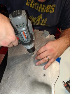
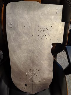
I purchased a 6.5" inch speaker and found that the outside of the frame was a bit wide of the aluminum shelf that I purchased from Benofkent. It has ears that can be used for mounting in a car but I will be using the holes in the frame to mount it to the motherboard. The ears were easily bent back with pliers which helped it fit within the shelf. I have drilled all the holes for the speakers and grills while countersinking them a bit to remove burs on both sides.

I don’t have the picture of the speaker and self at this time but this is my focus for the time being. I will get back to the wand once if all the locations and plans for the sound and lights shored up.

I’ve been working every night this past week on the pack. I’m close to finishing up the motherboard to then mount everything. I’m attempting to place the Moonlabs loom clamp in a way that I do not have to modify the mount at all. I think the loom can bend a bit once in the pack for this to happen.

I have drilled all mounting hose for the speakers, cyclotron shelf, sintra mount for the soundboard, Spengler plate holes, and hole to pass wires through the board to the Spengler plate.

Once I finish the loom clamp this afternoon I will be painting both sides of the motherboard in the same satin black as the pack.

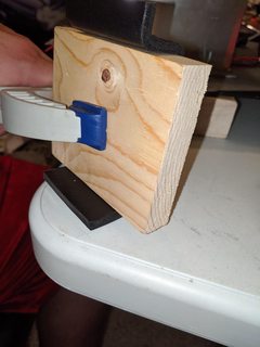
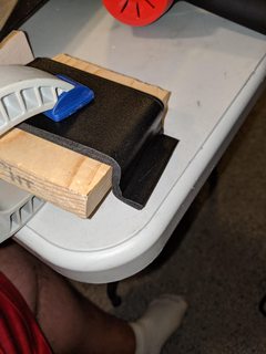
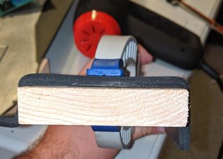
I heating up some sintra to create a small shelf to mount the soundboard to using nylon stands and screws. I used a block of wood and clamps to help shape this piece. Very easy to manipulate the shape of this material.

I may have purchased a bit too think a piece of sintra but it will work out just fine. I will also be using a piece to mount to my cyclotron shelf to hold the relay and cyclotron boards next to each other. This will most likely sit in the middle of the reflector cups area of the lights for the cyclotron.

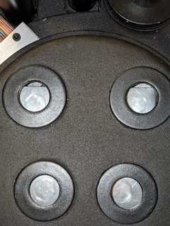
To mark the center points of the cyclotron lights, I mounted the shelf on the motherboard and placed the pack on. Then I dropped the reflector cups on the outside of the cyclotron holes to get the center points for the lights.

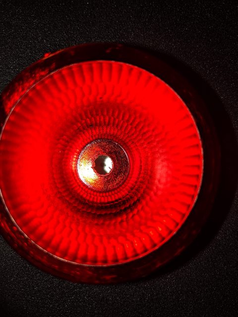
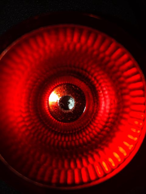
These a close-ups of the punch holes I made for these lights. I tried but it was difficult to see the center punch holes clearly but you should be able to see them a little bit:

I took a grinding bit on the Dremel tool to open the holes a bit to pass the LED light inside the cups. I will be securing them in the cups prior to mounting the shelf with possibly hot-glue or use the idea that canpara had with the sink washers. If I take the washer route, I will then mount the washer to the bottom of the reflector cup.

Power Cell Lights:

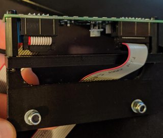
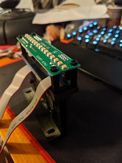
For some reason, I really had some difficulty in lining up these lights with the mount I have. I did purchase a power cell mount from Benofkent and this piece is very well built. I had to cut down the bottom portion as a result of the circuit board and the placement of the ribbon cable connectors.

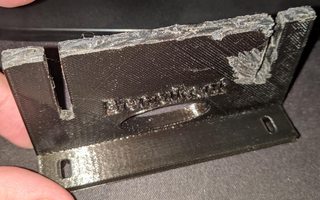
This was my make-shift mount until I had acquired the nylon standoffs and screws. I had to put this part off until I had those items to then modify the lower part of this mount and drill holes for the standoffs.

I cut about a 1/4" off the top of the base of this mount.

This is the top part of the mount. I drilled a 2mm holes in the mount and then tapped to 3mm. This allowed me to be able to hand screw in the nylon standoffs.

This is the image of it together. I didn’t get a picture of it in its place on the motherboard.

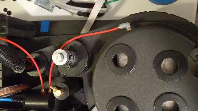
Here is a small video after I jockeyed the lights into the position and holding it with tape. Click on the image to view it. It will show the chase lights of the power cell. If it can’t be seen, please let me know. Sorry for the side angle. I recorded this on the phone vertically but it saved it on its side.
image

On a side note, I popped out the lenses so I could get a better view of inside the pack for all of the shelf and cyclotron stuff. I made the mistake and glued the lenses in before this step. I got ahead of myself a bit with that. Yet, I did mess up the lenses at little with the amount of glue that I used, so this was a blessing in disguise. I since have received replacement lenses because they all had some amount of glue on them that I could not remove which could be seen rather easily.

Since it’s a beautify day outside, it’s off to teach some baseball and then I’ll be back at it later.