Fitzhume - Proton Pack Build

My opinion is the 2 speaker setup is well worth it. But if you have concern, I’d recommend grabbing a set of the larger 5-1/2” speakers from a retailer like Walmart and hook up. Test. Then test the 4” speaker. If you don’t notice a difference, return the speakers.

No extra power required to run.

Thanks for the quick reply about this. I will pick up some speakers and give it a go.

By the way, the sound board is designed to work with speakers 4-8 ohms. If you get 4 ohm speakers, wire in series for 8 ohms. If you get 8 ohm speakers (unlikely), wire in parallel for 4 ohms.

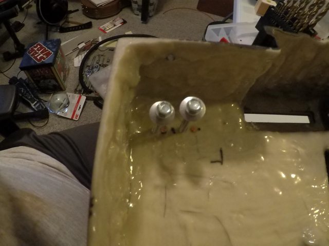
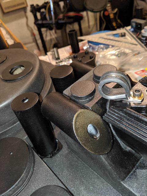
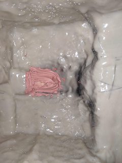
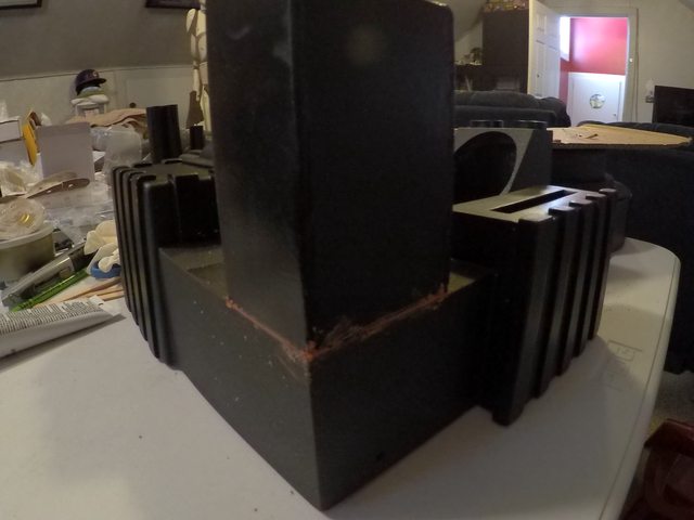
1st use of Bondo and the Ion block. This reminds me of putting my Stormtrooper armor together as I had one shot with the plastic welder at that time. It turned out better than I thought. As most have done in the past, marked up the section of the pack and the underside of the Ion block 1st with a grinding bit from the Dremel. After which, mixed up the Bondo and applied a layer on the pack corner and the underside of the Ion arm. Then used a square to make sure the block was flush with each edge. I then waited about 5-10 minutes and then flipped the pack over and drilled through the pack and the block at the same time. Finished attaching the block by driving in the 5.5mm self-taping roof screws.

You can see the 1st two holes that I drilled as a result of not thinking the process through. I originally thought to pre-drill the 2 holes in the pack, then hold the Ion block to the pack and mark the holes on the bottom of the block. Ya…that didn’t work as well as I thought it would. Putting the Bondo on plugged those holes with no problem.

I hope to get the booster tube attached tonight as well. I will be getting a block of wood placed snuggly inside at the right depth to expose the plug correctly.

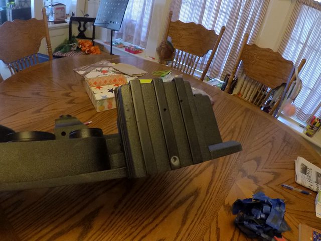
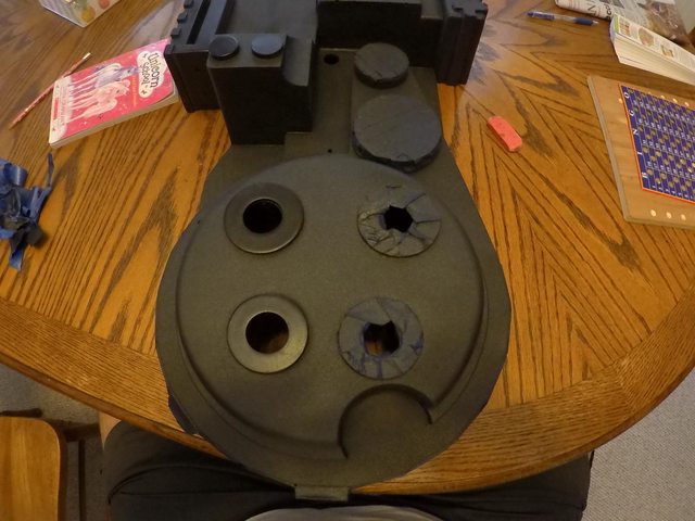
On a side note, these images do not do it justice as the two-toned with satin and truck bed liner looks really sharp.

Very nice work indeed!

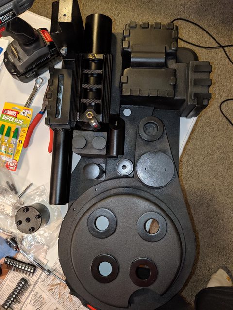
Thanks a bunch, Mario! I’ve actually been rather busy on the build since my last post. I’ve attached a good number of the accessories to the pack minus tubing and some make-shift Clippard elbows. I didn’t purchase the actual pieces so I have some painting to do.

This is a list of everything that I have attached since painting:

Ion Block

Injector tubes

Booster Tube

Booster Later

Painted/Weathered resisters

Painted Clippard 331 (pack)

I need to prime the Clippard elbows bases so I may paint them gold.

I had my first oops that I’m not sure how to fix or if I should worry about it at all. You can see that the PPD is a bit high. All measurements seemed to be correct but now after attaching it, you can see it is a little high and not flush. The image below you can’t tell from that angle though. I just liked that angle :slight_smile:

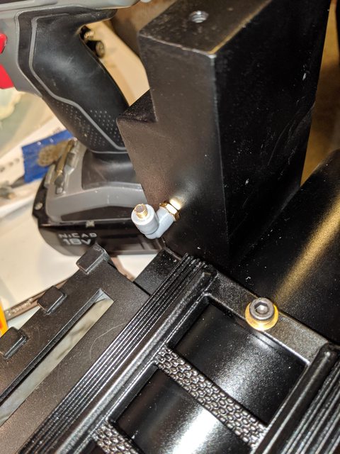
Elbow added to the Ion block. Tapped the hole and screwed it in.

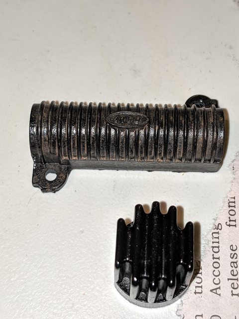
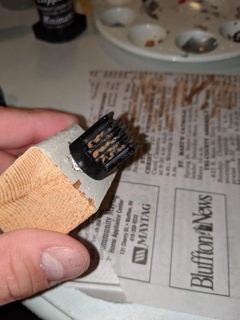
Here I added some brown leather paint to the resisters to give them a weathered look.

Before…

After

For anyone that has used resin resistors instead of the actual ones, what was the method of attaching the hoses to them? Or any ideas?

Next will be to work on gear box and tubing.

Prior to purchasing the genuine resistors, I just drilled holes into the replicas and used a bit of glue to hold them in place. You need only drill into them an 1/2” or so.

Alternatively, you could drill holes and insert small wood or metal dowels to slip your hoses over to better replicate the real resistors.

I like the small dowel idea, that way it can resemble the same type of hose setup from the genuine resistors. Thanks for the suggestion!

I think most of the packs ended up with resin resistors after GBII. They put in clippard hose barbs for the dale Resistors. This is easy and effective;

And it appears they just drilled a hole for the small sage resistor, probably because of the conical shape;

With the start of school where I work, I haven’t had much energy since my last post to do much. I’m waiting on some parts to finish the external pack and will be mapping out and drilling the mouse hole by tomorrow. I have my step bit ready for that. I just need to take my time figuring out where the placement of the BionicMoonLabs loom clamp will live.

1st update is the crank-gen loom. I decided to use a short dowel with the loom itself and bondo that in place. This was the easiest way for me to create more resistance that would hold the loom as a result of it needing to bend very quickly out of the hole.

As you will see in the following pictures, the hose fits no problem into the metal tube on the pack. I decided not to use glue, epoxy, or another dowel rod as there is enough pressure from the loom that it will not come out. If I find that it falls out, and it doesn’t seem like it can, I will address it then.

I will be using all GBFans sound/lights plus Spongeface’s TVG board and relay, I thought to use the frosted lenses that Spongeface was selling. I really liked the way they looked. In a previous post, I showed that I cut/ground the lenses down to fit in the recesses of the cyclotron. However, I did not take my time with the first two lenses when I installed them. I used a super glue gel but put too much in the seam which squirted onto the lense. I was not quick enough or thorough when attempting to clean it up.

This is the result:

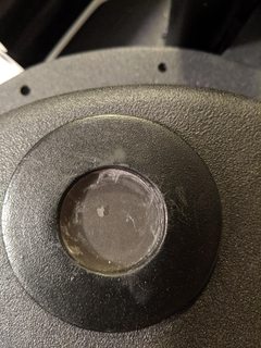
This picture is with a flash and it is rather noticeable. I attempted to use acetone to attempt to loosen the glue to clean it off. No luck so far. I will try some alcohol and see if I get any different results. I will update with what I find. The other lenses look good except for a fingerprint here or there from the glue that got on my finger. Those are hard to see unless I use a flash on them of course.

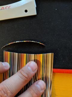
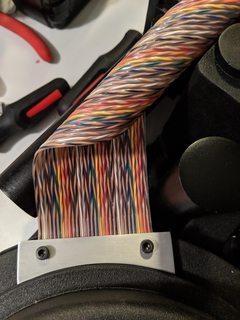
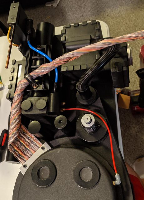
The Ribbon Cable - I used Canpara’s, and Pssdffjay’s idea (and I’m sure there are others) to trace the curve of the ribbon clamp and trim the cable to match.

The dark marks are from the sharpie that I used. Since this will be up against the cyclotron, you would not be able to see it.

[

](Imgur: The magic of the Internet)

Here it is installed:

I really like how the ribbon cable took to my rolling it. I still may add zip-ties to it to help keep its shape. Tomorrow I will also be adding a zip tie and tape to the end of the cable to keep it from working its way back out of the hole.

The other tubing that is not installed is due to a painting failure. I have painted miniatures in the past so I have a lot of paint leftover. I thought to paint up the 3d printer Clippard elbows gold for the HGA (not installed), beamline, and ion arm. This did not go well as I don’t have the correct paint to make it the gold that it needs. I ordered some replicas from the GBFan shop and once I get those, they and the hoses will be installed. The crank-gen knob will go on on a little later when I decide how I will be handling the volume control of the pack sound.

Not much of an update but I hope to ramp it up again this weekend.
[quote=Fitzhume post_id=4923030 time=1566528623 user_id=15884]I will be using all GBFans sound/lights plus Spongeface’s TVG board and relay, I thought to use the frosted lenses that Spongeface was selling. I really liked the way they looked. In a previous post, I showed that I cut/ground the lenses down to fit in the recesses of the cyclotron. However, I did not take my time with the first two lenses when I installed them. I used a super glue gel but put too much in the seam which squirted onto the lense. I was not quick enough or thorough when attempting to clean it up.

This is the result:

This picture is with a flash and it is rather noticeable. I attempted to use acetone to attempt to loosen the glue to clean it off. No luck so far. I will try some alcohol and see if I get any different results. I will update with what I find. The other lenses look good except for a fingerprint here or there from the glue that got on my finger. Those are hard to see unless I use a flash on them of course.
[/quote]

I had this same result using a fairly small amount of gorilla glue. As it dries, it releases it’s moisture and expands and creeps into gaps; which gives it that smudged look.

If you’re going for a heavily aged pack: this will work to your advantage as you’ve managed to already weather the lenses without even trying.

If you wanted the lenses clean: you’re practically out of luck. There’s very little that can be done to remove the glue’s effects without damaging the lenses.

I tried using alcohol, paint thinner, acetone and lacquer thinner. None were able to remove the smudges the gorilla glue caused — and also managed to etch and damage the lense. You’re likely better off buying a new set and starting over with those than spending hours and using solvents to clean them.

I know many builders think using the Crank Knob as a volume control is a great idea. It can be if you are okay with possibly being unable to adjust the volume while wearing the pack. Seriously, try the pack on and try to reach for that knob. I couldn’t reach it but I’m old and inflexible. From experience, I’ll say you’ll be at full volume much of the time. But there are occasions where you’ll want to adjust, sometimes quickly.

I’m not saying don’t do it, just give serious thought to best placement for your situation.

I appreciate this feedback. I keep going back and forth about it. At this time I don’t have a Spengler plate to put it there even though that is probably one of the better solutions. I may end up ordering one with charge cables with it. As for the knob itself, do people just make it a stationary piece or put a volume pod to allow it to still spin but without function?

I’ve seen it both ways. Personal preference really. Mine spins but doesn’t have any function. I partially dismantled a potentiometer so that I would spin without limit. I like that because the knob feels like it does something. I think I took a picture of this in my thread.

As for placement of a volume control, I put the pack on and reached for potential spots on the pack. In the end, I decided a knob centered on the motherboard roughly behind my kidneys was a comfortable location to reach yet reasonably well hidden. I tweaked the position slightly after marking to ensure it didn’t interfere with any components inside the pack. Definitely not “screen accurate” but that didn’t bother me. Also covered in my build if you’re still undecided and want to consider that option.

Bishop, what is the best approach with the loom clamp so I can still take the pack off to work on the motherboard? It would make sense then to use a mouse hole with the template, but what if you would like to do just a circle hole?

You’re still going to need to cut some or all of the ears off the smaller hole to allow the hose to clear so you can pull the shell off the motherboard. But mounting the clamp inside allows for a smaller more round looking hole, less a mouse hole.

But the hold itself will be close to the motherboard instead of the middle of the panel right?

Yes. I think the template shows the motherboard line for either type of hole. Round hole should be close to bottom of shell. Remove enough ear so the shell passes over loom.

So I didn’t drill the mouse hole yet but I have received the Clippard elbows and will be finishing up the pack here soon. I started working on the wand in the meantime.

Wand Construction -

I drilled out all holes needed for the rear box, trigger, box, switches, hat/dome light covers and opened the barrel and handle holes.

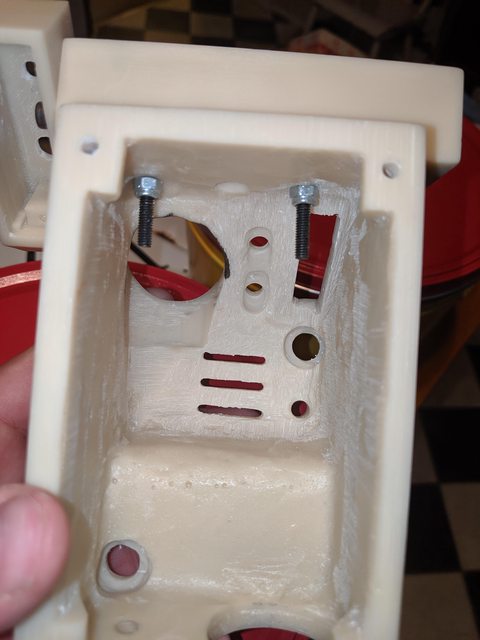
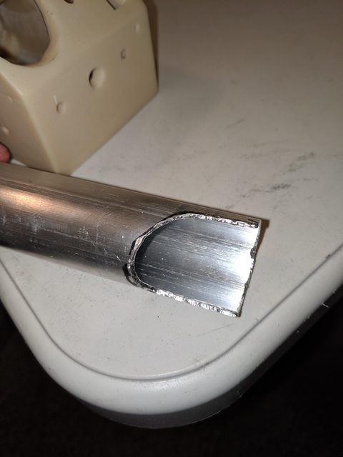
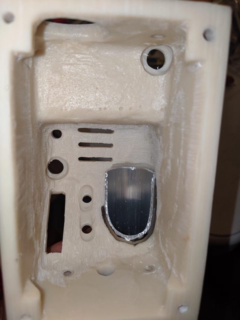
I created a little stop ledge for the rear handle, as well as opened the end of the handle that is in the gun box to allow for more room to get the ribbon cable and other cable routing later on.

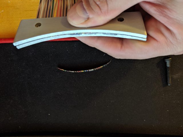
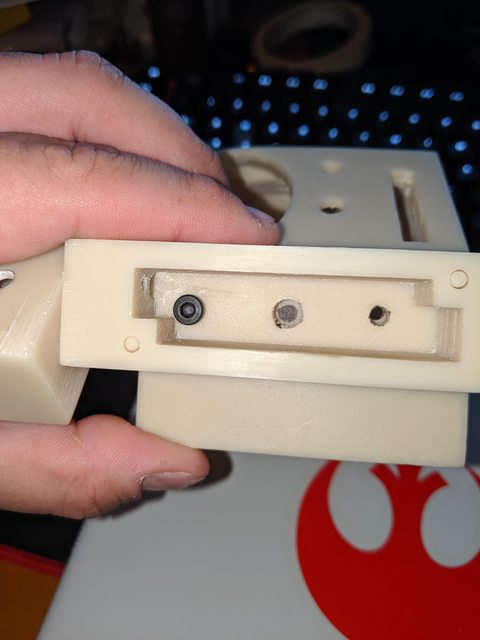
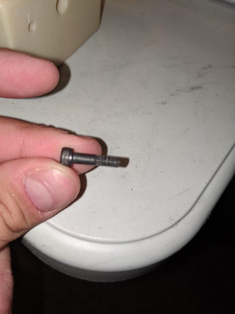
I ended up cutting these two bolts down so I could have more room in the gun box.

This is the cut that I created for the rear handle.

I also spent a lot of time, of course taking my time, in creating recessed areas for the switch boxes and light covers.

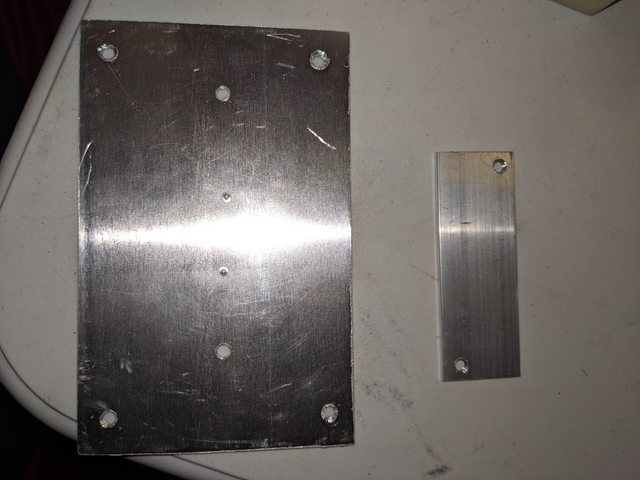
Here are the bottom plate and rear gun box covers. I need to re-punch the 2 spots for the V-hook at it is a bit off. I have not drilled these yet, but I will before I paint it.

I have widened the bar graph window to accept the Spongeface cover for the graph itself. It fits well and not snug at this time. I will wait until I mount it before filling the small gap with something. Here is an image of that window as well as everything put together for that gun box.

I think I’m ready to mount the front/rear cylinders and then handles. However, I feel that I’m missing something before I do this. Does anyone have any suggestions as to what I could be forgetting before moving forward?

As for getting the barrel lights and end of wand button and light to the end of the wand, is there a better way to manage this instead of using Bondo to mount the grip? If I do this, I cannot run a channel for the cables. Any suggestions would be much appreciated.

Looks like it’s there but make sure you have a hole between the trigger box and instrument bar. Once you mount those it would be difficult to drill a hole for wiring.

Not sure what you mean regarding Bondo and the grip.