Sadly when I opened my MT500… it looked nothing like i hoped it did.. I assume since I am missing the original board and the speaker I am SOL… and when I look at your wiring pictures the switches on the top of your radio look completely different than mine.. well at least one of them do anyway.. i dont know what do say. is there a way to remedy this situation?
There are some instructions (somewhere in the GBFans forums and on the web, it has been a bit since I searched for them), for “examining” the sound files from the video game. There are thousands of small sound bytes available, and I haven’t even gone through the sound effects portions yet. The actual DVD movie sound tracks can provide all of the rest.
After you get the quotes you want, then convert them to the correct format and program whatever sound module or “Bear” (?) you want!
Wow!, I guess someone really wanted to save as much weight as possible and removed everything they could!
The switches are probably fine. I have seen quite a variety of switches, but they all work basically the same way.
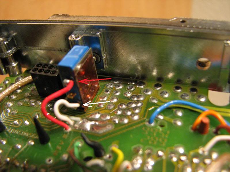
The power switch in the photo on the right (probably) should snap on and off and is probably on the outside two Red wires. It also looks like the center rotating switch is a 1 of 8 selection. The center pin(s) or one pin in the ring of pins will be common and the rest will individually short to that common pin depending on the switch position.
If you have a DVM or ohmeter, set it to continuity checking (beeps when the probes touch each other) or low resistance setting (Ohms) and go a probing! Just try different combinations and turn the desired switches. The switches should be open (very high resistance, megohms, but if you are touching things at least > 200Kohms) or shorted (less than a few Ohms).
I do have a decent selection of nice condition radios up for sale and also ended up with some fairly poor condition radios that I have lying around and use for spare parts. I probably have a spare beat up front panel + nice speaker available. I will check and let you know.
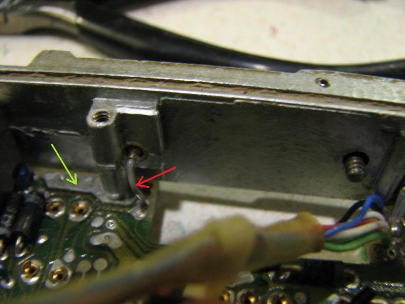
The talk switch may be a bit challenging to find the two connections. That looks a bit different that what I have seen before. Hopefully the small pin sticking out near the mounting screw hole is one side and the ground is somewhere on the circuit board on the right.
I have seen some talk switches that are just mechanical - no electrical connections, and that would require some external switch to sense the motion. You can see if this is an issue by pressing the talk button. If it moves in/out and you don’t see any movement of the pin on the inside, then it is probably an electrical switch inside the button. If you do see the pin moving in and out, then it is way more complicated to get working since they removed the board that would hold that switch.
The arrows in the photos below indicate where we would normally solder the talk button ribbon cable wires to.
Here is the “Electrical” switch, no movement of the connection can be seen from inside:
Sponge , did you send me a pm recently ? … Besides the " kits are available now " pm . … I got an email saying i did, but it wasnt formatted correctly and it wouldnt let me read it
If I understand correctly “regular” only has static before the lines if you let it play automatically throught the timer, but doesn’t have static if you play the lines manually with a push of the button. While “extra static” always has static.