How did you prep your shell, Filandrius? Wet sand or regular? What grit did you use?
Both! I started with dry 100 grit for the rough spots, patched a bit with automotive spot putty, swtiched to dry 150 grit, did the whole thing, then almost died because of the dust. Then I switched to wet 200 grit, did the whole thing, then wet 320, wet 400, then I painted the shell with silver paint. I repatched a couple of spots that I had missed, re-sanded it (wet up to 400 again) repainted it, then wet sanded the whole thing with 1000 grit. Then I painted it black! 
Thanks a lot for the kind words, by the way. That’s really appreciated. 
All labelled up! I also installed a few things here and there. Can you spot them? 

My shell is REALLY starting to look like a proton pack now. Things are getting exciting! 
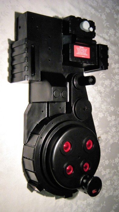
That’s it for now!
EDIT: No, the crank gen label isn’t that pink. In fact it’s bright red. My digital camera sucks. 
Looks great! Do all the remaining parts just screw onto the shell?
Yep, except for the crank gen tubing, which I’ll epoxy on, and the potentiometer under the crank knob, which I’ll propably replace because the 1/4" shaft isn’t long enough (the knob doesn’t stay on) I’m also missing a few parts which are on order (the HGA and the injectors) Aside from that, it’s lag bolts and washers for the ion arm and the filler tubes, and cap head screws and nuts for everything else. Almost everything is screwed on, except for the parts I don’t have a choice; I don’t trust glue. I’ll post pictures of the inner working of my shell tonight.
Also, I forgot the red band around the N-filter! Note to self: apply red band!!!
EDIT: Pictures!!!
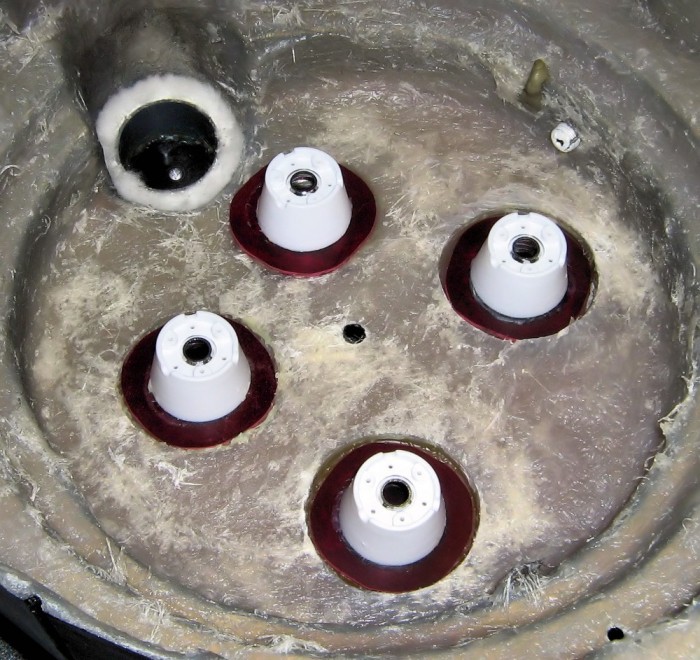
The lenses from the inside. Plastic welded into place. Note to self: acrylic lenses are very easy to scratch. Also, I used a short length from a white paint roller for the inside of the N-filter, also plastic welded into place.
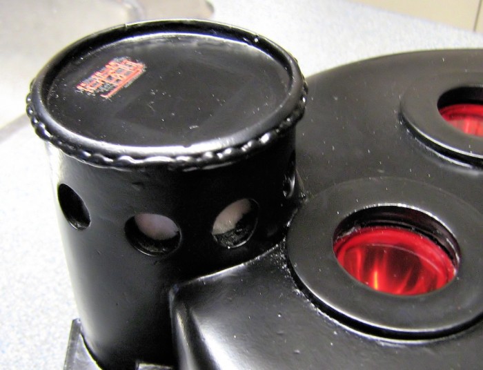
The result. Don’t ask me about the fact that I don’t have mesh in the holes, from some reason I don’t like how it looks. So no mesh it is!
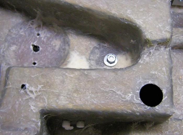
A whole lotta holes! Here you see the holes for the Clippard (with the little notch in the center hole so that it’ll stay put) the end of the crank gen loom tube (lag bolt in a short wood dowel) There’s also another hole for one of the filler tubes, which will also be installed with a lag bolt. I blatantly stole this method from Libtechinit, including the wood dowels in the tubes held together with epoxy. You can also kinda see the Legris fittings, screwed in the tapped holes with a whole lotta Teflon tape.
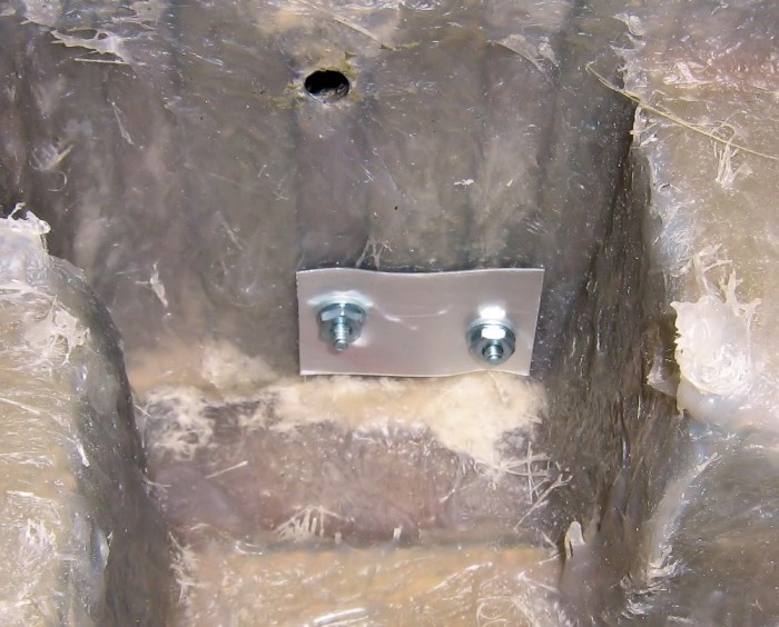
The V-hook. Screws, nuts, washer, and some sheet metal that I had around to be safe. Nothing to it.
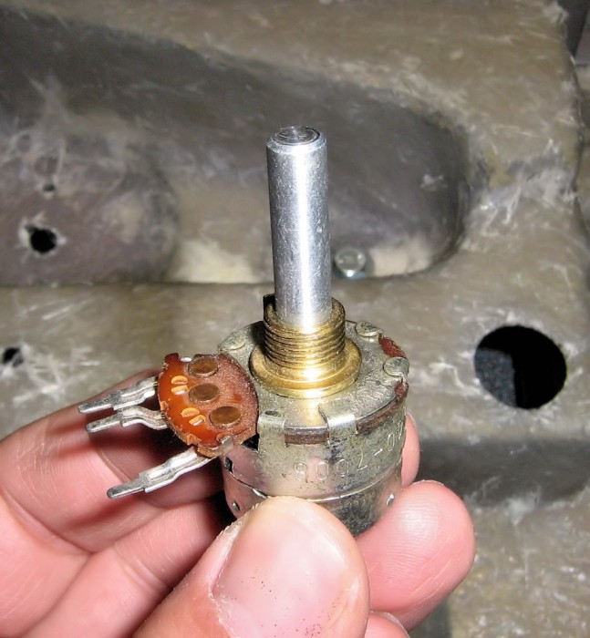
Today I removed the potentiometer that I already installed for the crank knob I purchased some new potentiometers, with longer shafts. Here’s one!
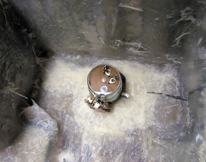
Here it is JB welded in the shell…
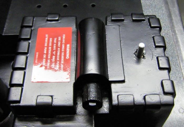
… And here is the result. The crank knob will be very easy to install and/or replace this way, be it real or resin. Just slip it on and use the set screws! Plus it will really crank!
I think that’s all for now. Stay tuned! 
It’s coming along nicely, don’t you think?

I’m mostly waiting for parts for the rest. I’m missing a resistor on the ion arm, it’ll be easier to install it if it’s loose. I’ll wait for my HGA and injectors to get here before I install any tubing. And the ribbon cable is on its way.
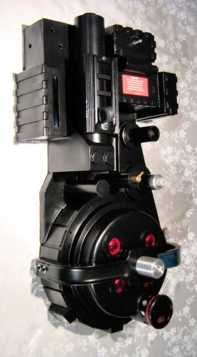
Look! There’s a red band on the N-filter!
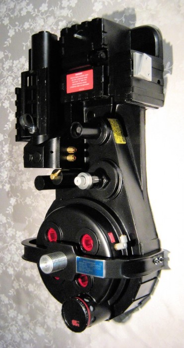
That’s all for now, I had to share before I go to bed.
I think its neat you used a real pot in the gearbox. That’s how I turn on/off the lights on my pack.
This reminds me, I need to get labels for my pack…
that’s an awesome idea for the crank knob… I might steal that idea to turn on my sound board when I get it!
Lookin good Filandrius!
Hmm… I noticed the thrower is strangely absent… must have some special plans for that little guy… 
but while you’re waiting on the parts to arrive… WEATHER THAT THING!! 
Chris: I was perusing my local electronic store, and when I saw those I immediately thought that is was the safest way to mount the knob. Simply gluing it to the shell, or screwing it from inside, isn’t clean enough in my mind.
And labels are a must! They really add something to the pack, like it’s really a dangerous electrical (or in this case, nuclear) device or something.
Zeta: I thought the same thing… Actually when I get my sound kit I might wire the potentiometer to control the volume. Might be cool, I think.
1.21: Thanks! And I DO have special plans for the thrower, and that thing is going to be a dozy. But that’s a story for another day.
Ah, the weathering debate. Weather or not weather? I plan to, but I can’t bring myself to do it, and I keep bringing out excuses not to. My current excuse? Since the “real” pack is weathered because of use and abuse during ghostbustin’, it’s logical that weathering occured AFTER the pack has been completed. So I’ll weather mine when it’s complete. THAT’S MY STORY AND I’M STICKING TO IT!
Oh and I took some more pictures when I got up this morning, in the sunlight this time. They’re marginaly better. I hate my digital camera. Enjoy!


Looks awesome in natural light!
Thats one Gorgeous pack you have there !
Yeah I guess it’s alright for a non-cake pack
I knew I was forgetting something. A pack made out of angel cake would’ve been much lighter at conventions.
OK! So I got my missing resistor from Colin (that was faaaaaaast) and I completed my GB1 ion arm. Completing the ion arm made me complete the tubing to the PPD, which mean I could install them both! So, presto!
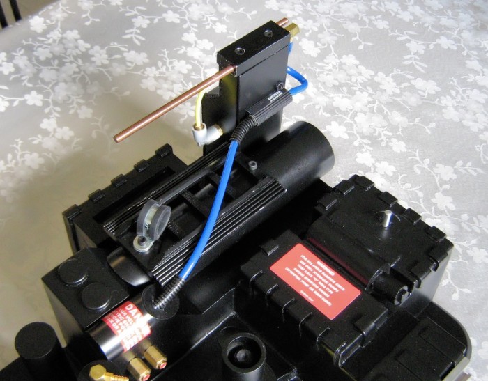
After all they’re installed with 3 bolts (1 for the PPD, 2 for the ion arm) so it really wasn’t a chore. And I couldn’t help myself, it was still light outside… Some new pictures of my pack!
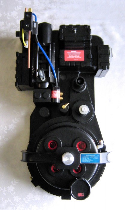
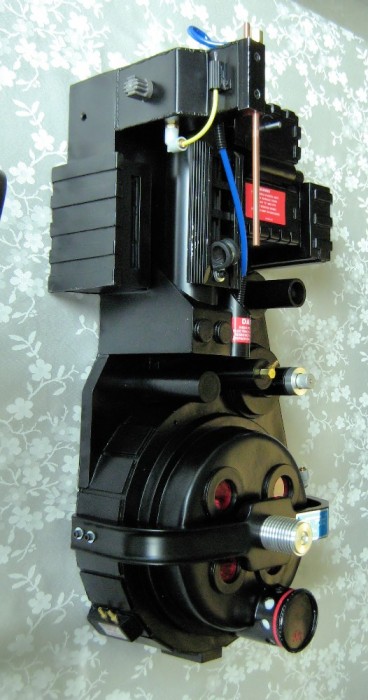
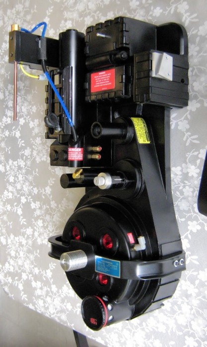
Next one will be cake, Nick. I promise.
AWESOME work, Filandrius! You’re starting to make me nervous as to how my build will turn out (hopefully like yours!).
Is that a metal booster frame?
Thanks, Kaga! That’s appreciated. I’m sure yours will turn out pretty nice as well.
You have good eyes, Nick. That’s exactly what it is! It’s an aluminum booster frame made by Jason (jpa35) It’s a work of art, that guy is a genius with aluminum (just go look at that ion arm that he just posted in his profile… Grrrrrr! I want one! :P)
That reminds me that I haven’t mentioned your PPD… Yep guys, it’s a metal PPD, custom made by Nick for yours truly. I couldn’t ask for more! Thanks man!
Jasons work is top notch and that booster frame is on a whole new level of coolness
No worries about the PPD, glad I could help you in this great build!
Great words from a great guy. Thanks Nick!
Okay! New update. Since my build has slowed down considerably (because I mostly installed everything that I have :P) I was thinking that maybe I’d show a little bit more of the inner workings of my pack. Usually I just show the latest thingy that I installed, because I’m not a patient man and that pack needs to be completed, gosh darn it!
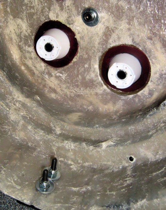
Here we have the interior of the cyclotron, with the bolts that hold the bumper in place. 10-24 cap head screws on each side, with small washers outside and big washers inside. The Exoray/jpa35 shock mount is held in place with a long 1/4-20 cap head screw, with 1/4" aluminum spacers on each side of the shell (inside it’s mostly because the bolt I used was a tad too long)
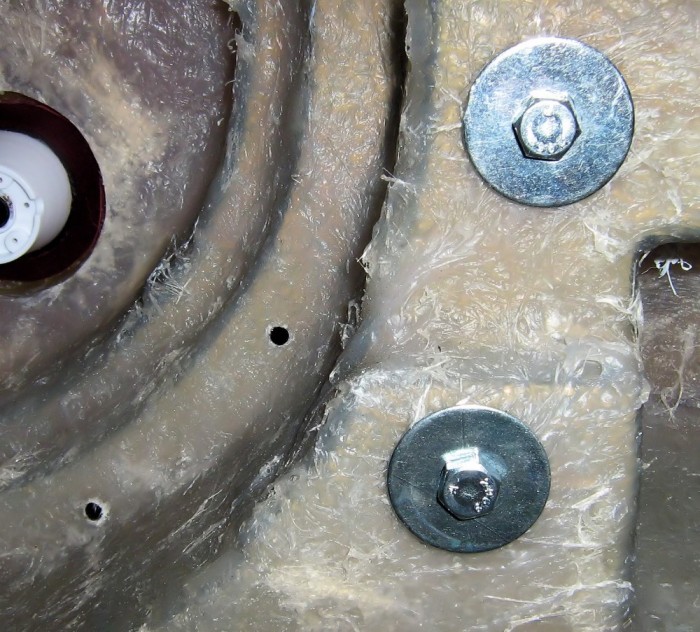
The filler tubes. 1/4" lag bolts in wood dowels, with large washers. These things can easily be used as carrying handles. You can also see where the ribbon cable clamp will be installed, with 8-32 cap head screws, nuts and washers.
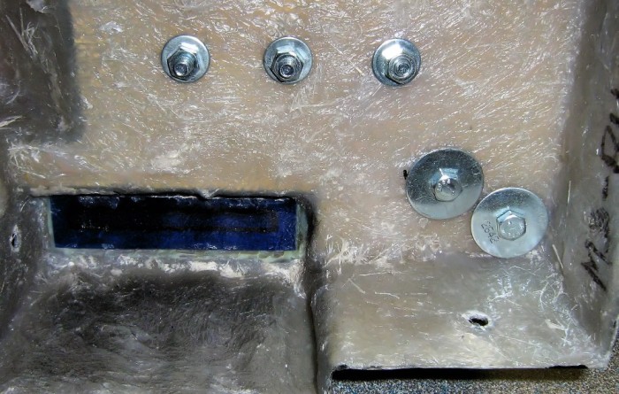
These are both the booster tube and the ion arm. Two lag bolts with large washers in wood for the ion arm, and three 1/4-20 bolts with nuts and washers for the booster tube. Everything is rock solid, and can also be used to carry the pack.
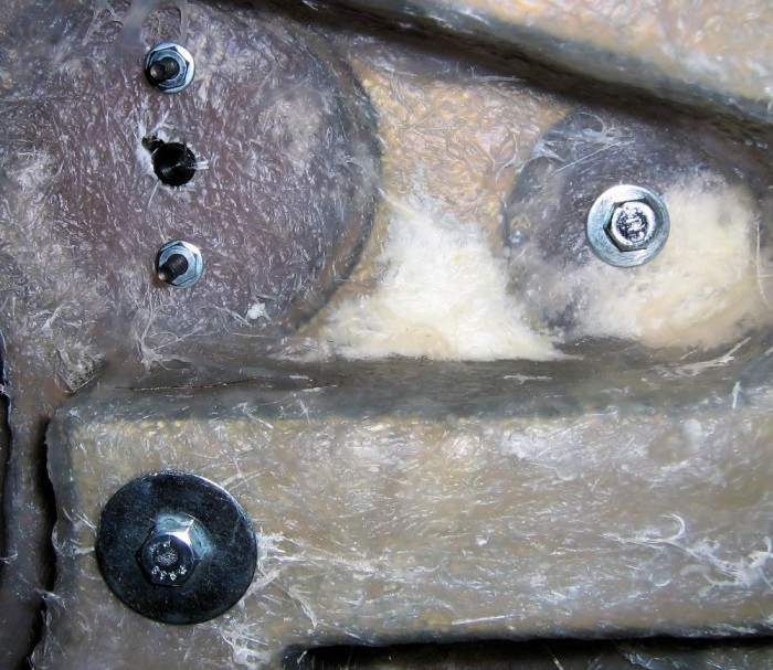
Finally we have the Clippard valve, bolted on with 2 8-32 cap head screws with nuts and washers. I didn’t have to use some metal plating like I planned to because the fiberglass is thick and even under there. We also see the lag bolt that holds the wood dowel of the split loom in place…
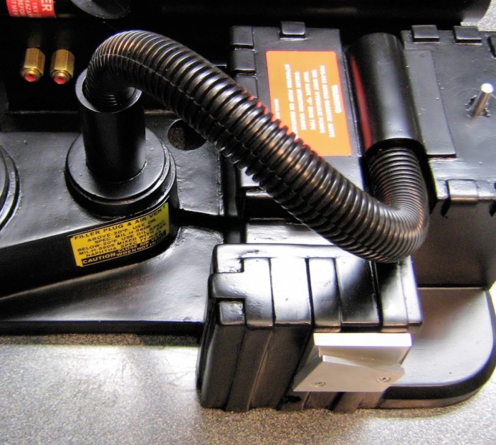
…Which I installed today. Held in place with JB Weld on both ends. That thing isn’t going anywhere.
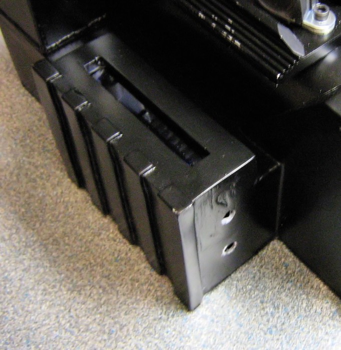
Here’s a (blurry) shot of the power cell, with two new holes on the bottom. These are for the injector tubes.
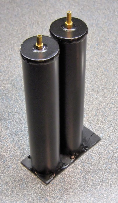
And I’ve got them today! Injector tube assembly, with welded base plate, by Chris (CPU64) These things are great. Here they are, freshly painted by yours truly, with a couple of spare Clippard barbs that will hold the injector tubing in place (I have some on the spacer too) Don’t worry, they will be covered by the loom boots.
Well, I think that’s all for now. No, I’m not installing my injectors tonight, I want that paint to be dry and cured. Patience is the name of the game! Stay tuned!
Dude please tell me where you ordered that shell from! id love to get my hands on that one.