I have seen here a lot of posts and videos. but i could not find a satisfied desription (for me - i am a beginner) where the wiring of an arduino for the electronics and the sketch is completed.
so here is my question: Can anybody give me the right posts here or maybe someone can help me with a step by step instruction just for the arduino electronics (prefer with adafruit wave-board - others also OK ) for a proton pack?
Hello! I have around two years experience. The best way for you do do this would be to learn Arduino and basic wiring in all honesty. Start with how to make a blinking LED on Arduino. That’s where I started. I personally use a millis chaser circuit which essentially is a timer that doesn’t use delay so that you can use many different timers at the same time and have them not interfere with each other.
I used the adafuit wave shield for mine but be aware that it is not meant to work on the mega boards, I have had no luck with trying to get it to work on there. On mini boards it works brilliantly though.
I’d give you my code but I accidentally deleted it when I moved laptops. Eventually I’ll have to rewrite it.
Don’t worry, Arduino language is really simple. I say you should learn it because if you’re taking code from someone else you can read through it and understand the wiring yourself or even fix issues that may be present. You can learn all you need to do this project in probably a few days to be honest.
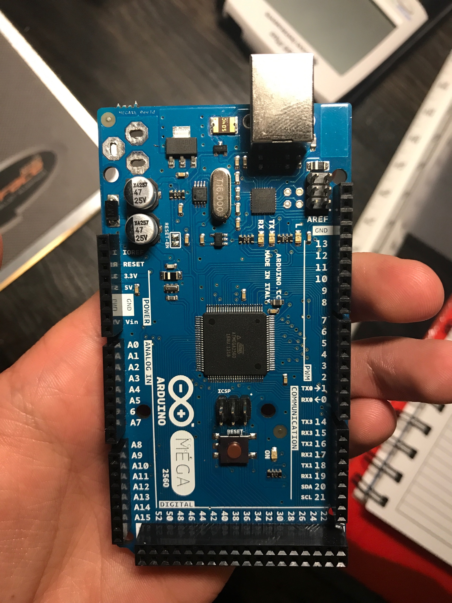
It has a lot of pins but not all 54 can be used for that purpose. Most of them can but some of them are specific for functions of the board such as ground, Voltage in, voltage out and reset
Ah Ok I had not seen a Mega up close. It looks like one Mega is not enough to do all the individual LEDs for a pack and wand.
It is also larger than thought. With all the LEDs and switches in the wand I thought it would be easier to put most of the electronics in the wand body but this will not fit there.
For my pack that’s what I did with the mega. I don’t know if I had the correct number of lights though. If need be you can get creative with some IC chips such as the LM4017 To create some chaser lights. All you need to run to that is a pulse to activate the next light in sequence. I haven’t personally done it that way but I know it would work
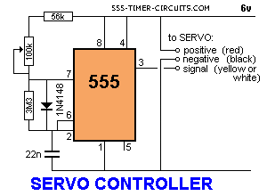
The ghost trap uses a servo and a 555 timer circuit to change between two preset positions. A servo has three leads, a positive, negative and a “signal” that can control the position by supplying a specific frequency. The higher the frequency, the further it rotates. I built this circuit: http://www.555-timer-circuits.com/images/ServoController.gif with the modification of having two resistors and a switch where the 100k potentiometer is between pins 7&8. One resistor sets the “open” position, the other the “closed” position. You will have to experiment with the resistor values to find the correct “throw” for your particular linkage on the doors. The linkage I used was a stiff cable similar to one from a bicycle braking system that runs through tubes and pushes/pulls the doors open/closed. you could use two cables, both connected to the servo, or a “Y” shaped one that splits under the mirrored bottom like I did. The servo is mounted in the front under the display, and operates the hinges in the rear. The pedal contains the switch mechanism and the two resistors. Press it once, resistor 1 is active, press again and it switches to #2. The main power switch in the rear turns it completely off. Batteries are mounted in the rear. The center section is removable like the movie prop, with a 3 prong plug connecting it electrically to the base, and hard drive magnets and washers to keep it from falling out. The mirrored bottom is a cut up laserdisc that reflects white leds installed in clear straws up under the top by the doors.
By the way, for anyone attempting to use an arduino for a proton pack, let me address some issues I had with that.
The arduino does not like doing too many things simultaneously. It is a very “serial” device. Getting it to cycle the cyclotron lights WHILE running the bar graph power meter WHILE playing a sound… proved difficult. That’s why I farmed out some of the simpler tasks to auxiliary circuits such as a 555/4017 circuit, or a self blinking led. I’m sure it can be done, but it might prove to be kind of convoluted during the programming process. I guess it depends on how complex you wish it to function.
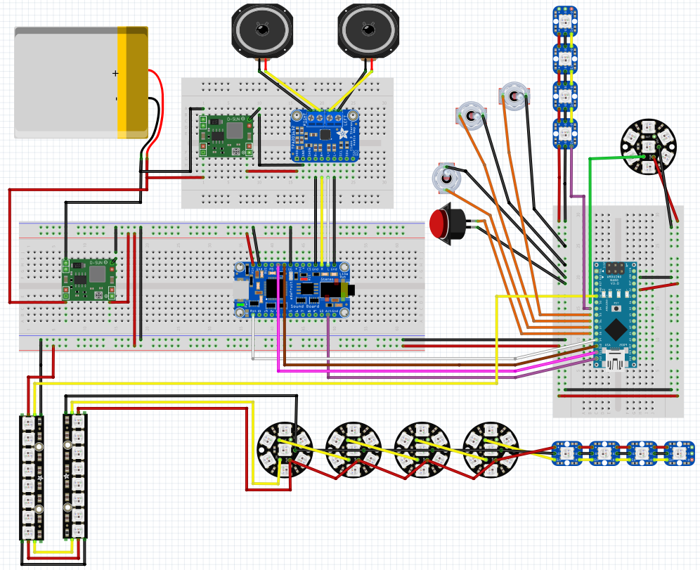
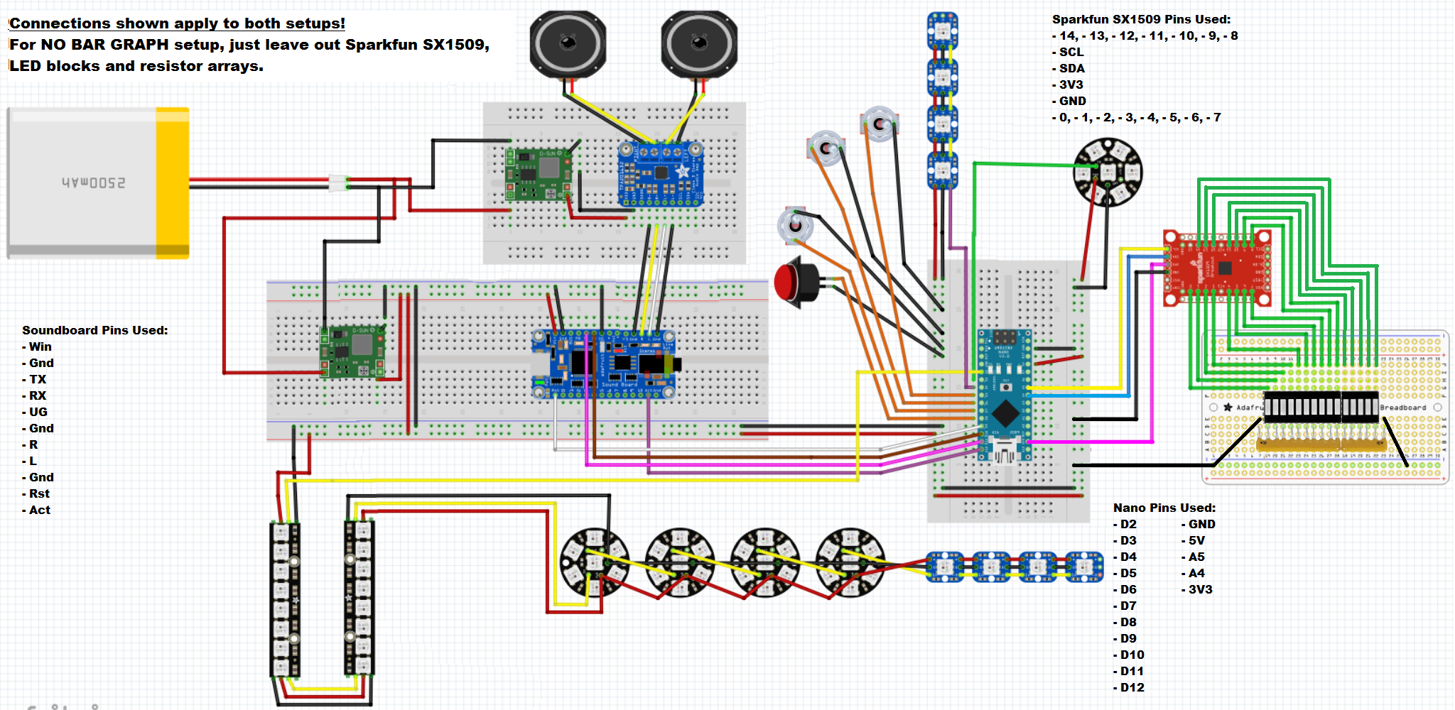
Here’s my arduino proton pack electronics using a nano for the control, adafruit fx board for the sounds, and neopixels for the lights. You can use the mega with this code no problem but I was able to fit everything I needed on the nano.
There are two circuit diagrams. A simple one for just sound a light control and then another for a bargraph. If you are using a mega you do not need the SX1509 as you have plenty of outputs. It would make things much easier and you could still use the majority of my code.
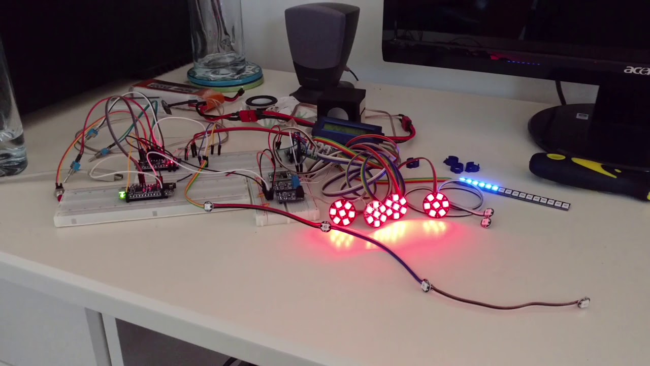
Latest video of the setup without the bargraph. I’m building an 83% pack for my son so can’t fit it in at the moment:
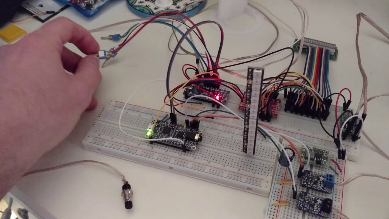
Here’s what the bargraph looks like. This was earlier code but the bargraph code was completed