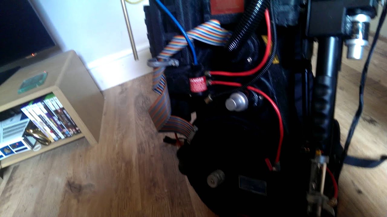
TheBigGuy's Arduino pack lights WITH CODE

Alright party people, only two days until Halloween! I’ve had a handful of people contact me asking for my Arduino code and I haven’t written a thread about it yet, so here it is.

First of all, my code isn’t perfect. Proton pack lights were my first reason to use Arduino, so I learned just enough to write a code sketch that worked for me, using only LEDs and resistors (no other timers.)** I have a sketch for UNO and for MEGA.** Neither is screen accurate, and there is undoubtedly better code out there, but I don’t mind sharing mine to those who might find it useful.

Here are a couple reasons why you might want to use Arduino for proton pack lights in light of the drawbacks I’ve listed above:

  1. You are in a pinch and you really need a solution using parts you can find locally… today.

  2. Like me, you are really into DIY (doing things the hard way, even if they will be less perfect, because it’s a pride of the build thing.)

  3. You want a starting point for writing a more complex light code.

I have two sets of code, one for Arduino UNO/Duemilinove and one for Arduino MEGA. I’ll do my best to outline the channels for each, but I have not drawn any diagrams, so do your best to follow my descriptions.

NOTES ON SOUND AND POWER: - [A.] Either of these will work with any sound board while using DPDT switches. (Many sound boards do not require DPDT)

  • [B.] Because arduino takes a couple seconds to boot, you may want the board power on a hidden switch. Using that configuration with your “power up” switch in the GROUND side of the circuit for ALL LEDs will give the effect that all is powering up with the flip of the switch (because you have already booted the Arduino with your secret switch) You really need to run a single ground back from the wand anyway to save wire space in your tube, putting your pack ground through there also only adds one wire and gives the effect of the entire pack coming on with one wand switch.

  • [C.] The info here assumes you know enough about circuits to figure this out. I’m not going to get into what you will need on each circuit. I don’t know what LEDs or resistors you have available, so I’ll ask you make those calculations youself, thanks.

**Good luck and have fun! **


LESS ACCURATE CODE FOR UNO/DUEMILINOVE

Download code here: http://www.portlandghostbusters.com/PackBuild/ProtonPackUNO/ProtonPackUNO.ino

Channel 1 - Wand tip flasher (flash runs constantly in code, wire your switch on this circuit to activate/deactivate)

Channel 2 - Power Cell

Channel 3 - Power Cell

Channel 4 - Power Cell (wire any flashing wand lights to channel 4 or 5 for a steady blink)

Channel 5 - Power Cell

Channel 6 - Power Cell

Channel 7 - Power Cell

Channel 8 - Unused (Wanna get creative? write some code for channel 8 or 9 and do what you want!)

Channel 9 - Unused

Channel 10 - Cyclotron

Channel 11 - Cyclotron

Channel 12 - Cyclotron

Channel 13 - Cyclotron


MORE ACCURATE CODE FOR MEGA(though still not totally screen accurate, no switching modes)

Download code here: http://www.portlandghostbusters.com/PackBuild/ProtonPackMEGA/ProtonPackMEGA.ino

Channel 2 - Always on (wire any LEDs that you want solid on to this channel)

Channel 3 - Wand tip flasher (flash runs constantly in code, wire your switch on this circuit to activate/deactivate)

Channel 5 - Power Cell

Channel 6 - Power Cell

Channel 7 - Power Cell

Channel 8 - Power Cell

Channel 9 - Power Cell

Channel 10 - Power Cell

Channel 11 - Power Cell

Channel 12 - Power Cell

Channel 13 - Power Cell

Channel 14 - Power Cell

Channel 15 - Power Cell

Channel 16 - Power Cell

Channel 17 - Power Cell

Channel 18 - Power Cell

Channel 19 - Power Cell

Channel 20 - Wand Bar Graph

Channel 21 - Wand Bar Graph

Channel 22 - Wand Bar Graph (wire any flashing wand lights to channel 22 for a steady blink)

Channel 23 - Wand Bar Graph

Channel 24 - Wand Bar Graph

Channel 25 - Cyclotron

Channel 26 - Cyclotron

Channel 27 - Cyclotron

Channel 28 - Cyclotron

Mighty fine job there.

Thanks AJ!

This is great!

Thanks!

SWEET! I was just looking into Arduino. Thank you so much.

No problem folks, hope it gets you somewhere!

hi i have a question im hoping to use this code for my pack with the mega arduino ive wired up my gun but my bar graph has 10 leds and the code is only for 5 where do i put the other 5 leds ? do i just double them up ? sorry for being a noob

No worries Peter. Doubling them up would be one option, and would probably look reasonable to most eyes. The Mega definitely has enough pins for 10, but the code would need to be modified. Also, I believe I went with 5 because that’s what could be supported by two cat-5 cables running to the wand (in addition to everything else going on out there.) I may be wrong about that but it’s a little late for me to wrap my brain around the exact setup of something I put together a couple years ago :slight_smile:

If you are interested in doing more than doubling up, reply here and I can try to take a little time tomorrow to tell you exactly what expansion would require. Cheers!

ok i doubled up and changed the location of the leds and got a great effect and all looks good see here.

ok that is working from my battery pack i used for my ironman helmet which had 2 sets of leds 2 servos and an arduino it worked ok this using the switch as seen in the video but when i istalled it in the pack and also installed the power cell nothing works i stripped out all the wires and istalled one at a time and nothing the gun is now dead but the power cell works on its own ive tested the board with single leds and the board is fine but when i try the battery pack with single leds it blows them i dont see how it worked before and not now the battery pack is 2x 3.7v batteries looks like im going to have to rip out the gun and start all over :frowning: thats what you get for not using resistors i guess that will teach me

Total newb to arduino, and I’m fairly certain I have everything wired up correctly. Currently, I’m trying to add lights in phases, starting with the pack.

I don’t imagine anyone could assist me with cutting this down to just the cyclotron and power cell lights, could you? I would be muchos appreciative!

Hey, no prob. You can use the same code and just not wire anything to the channels that correspond to the lights you don’t intend to use. There are two plans in the first post on the thread. You could use the first and simpler of the two (UNO/DUEMILINOVE) and just not use the unwanted channels.

As long as all the desired LEDs are on a complete circuit from channel to ground, it won’t matter that there’s code running for unused channels.

Y’know, I did just that and it works like a charm. You rule. I have it all functioning just fine on the breadboard. My next questions would be:

Can you offer any suggestions on what I would do to get this off of the breadboard, and into the pack? Is it all coming off of one circuitboard? Do you have separate PCBs for the cyclotron part and the power cell part? I’m so new at arduino, and electronics as well, but I feel like I’ve made some major progress getting this far. Do you have the arduino in the pack, or did you perhaps take the sketch and flash it to a memory chip/rom to run independent of the arduino? Wasn’t sure if I could take the sketch from the mega, and upload/flash/burn/whatever to an AtMega328 (similar to how you can take the AtMega328 off of the arduino Uno and simply use it on your finished PCB) If I could at least get the pack lights in before October, I would be thrilled. I’d spend the next year working on other components like the wand, sound, etc. Baby steps, to quote a familiar celebrity.

So, in no way did I do any of that wiring the “right” way, and probably no one would encourage you to do it the way I did. I just needed to use what I had lying around when I made my pack. Groups of wires basically run throughout my pack to where they need to go via ethernet cable or IDE cable. I don’t have any experience soldering PCBs, so every LED and resistor is soldered directly to the ends of the corresponding wires, with the connections wrapped in heat shrink.

In the case of the cyclotron and PowerCell lights, each has a backing plate installed behind the lens with holes drilled in it where the LEDs are seated. Again this is not the way most people do it. Most people do have PCBs in their packs (anyone who buys a light kit, or he’s good at using PCBs) and then it’s just a matter of mounting the PCB in the proper way to line up the LEDs with their lenses.

When I built my pack, 15 seemed to be the number most people agreed on for the PowerCell. But details about these things change over the years as discoveries are made (i.e. people in the community get their hands on a stage used prop that’s never been seen before) so I can’t say I have my finger on the pulse of the proper number of powerCell lights at this time.

Good luck my friend!

To your first paragraph, it sounds like we’re using the same method, hahaha!

Before reading your response, I actually popped into Radioshack (I just…popped in there), and picked up wiring, soldering stuff, and heat shrink. So I guess I’m using TheBigGuy method, here. I found 4 old, cheap flashlights at a local ■■■■ shop for $1 each, so I’ll use the reflectors from those for the cyclotron.

I’m curious, though, as to how you’re using ethernet cable.

And finally, so your adruino is actually in your pack, then?

Hey all,

I started my pack last year and went the arduino route as well, but instead of wiring one LED to a single arduino output or using shift registers, a friend suggested that I use a TLC5940 LED driver to control the leds. What this means is that I have a single arduino uno controlling all my pack lights and I’m only using 5 outputs. Even better, rather than only being able to turn the LEDs on or off, I have 4096 levels of brightness, so the lights can fade in and out and do some neat tricks as well.

I’m a software engineer by trade, so I developed an arduino library for controlling the pack and the TLCs, this also includes handling the switches on the pack. The advantage with this approach is that now your lights are controlled via software that’s easy to use and doesn’t have any sleeps (delay(50) in the code above), so you can control the speed of the lights down to 20 milliseconds or so. Do you want your gun graph to not climb at the rate of your powercell? Done. Do you want your cyclotron lights to fade in and out? Done. Do you want your cyclotron to speed up during firing? No problem. Do you want your wand lights to blink your name in morse code? You get my point. The other benefit of my approach is that tuning one component won’t throw the rest off.

My hand-soldered boards from last year were very buggy and time consuming to make, so this year I had PCBs made to house the TLC and LED connectors which are absolutely tiny (1.47" x 1.7").

Why am I posting this? Well, in the spirit of open source, I’d like to donate my pack library, PCB schematics and parts list to the forum if there’s interest. I’m really happy with how the code turned out and how easy it is to create and manage new pack pieces, and hopefully you guys will benefit via cleaner, easier to maintain packs.

I’m also pretty sure my library can be modified to support the ‘direct to arduino’ approach everyone else has taken.

I’ll post pack videos if there’s interest.

-Steve

Scohen, I’d be interested to see a build thread for everything you described. I’m working on a custom pack that could possibly use those 5940s you describe.

Awesome! Been doing stuff with arduino for the last couple of years and look forward to seeing your work.

You could use Fritzing software to show how to hook up the wires and such…great software!

Thanks all, I’ll start a build thread and post a link when I have something. In the mean time, I put my code up on github with a tutorial. Tell me where it gets confusing.

I finally got around to posting some videos. Curious to hear what you think: