So, I finally got started yesterday, and I think I’ve made some decent progress. I spent almost 9 hours yesterday, and about 7 today working. So, down to business.
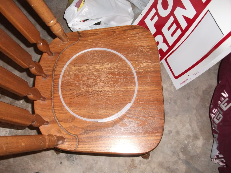
Some vinyl hose I found at Home Depot. I’m going to use it for the tubing.
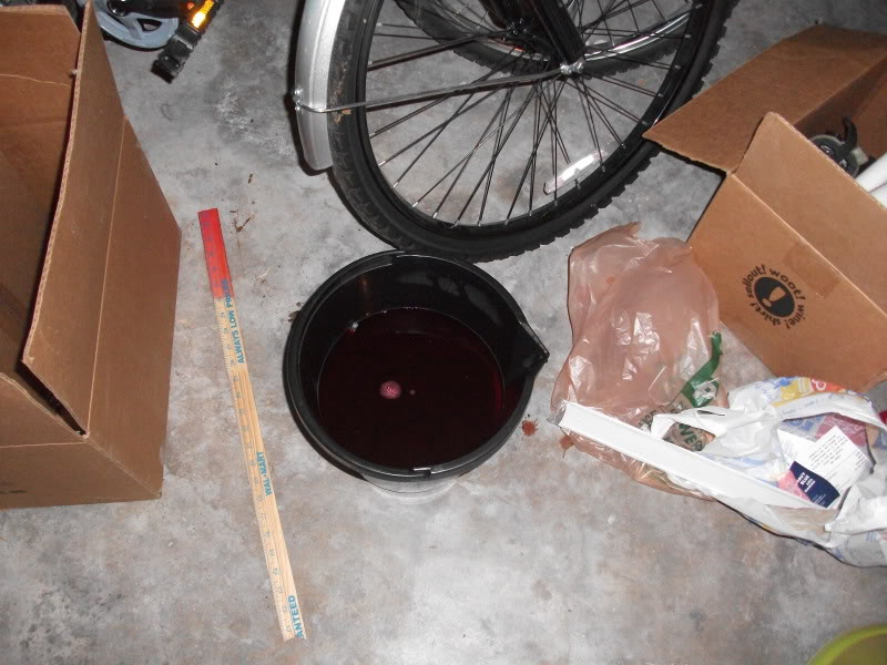
I tried dyeing it with RIT, but it turns out that doesn’t stick to vinyl AT ALL. Whoops.
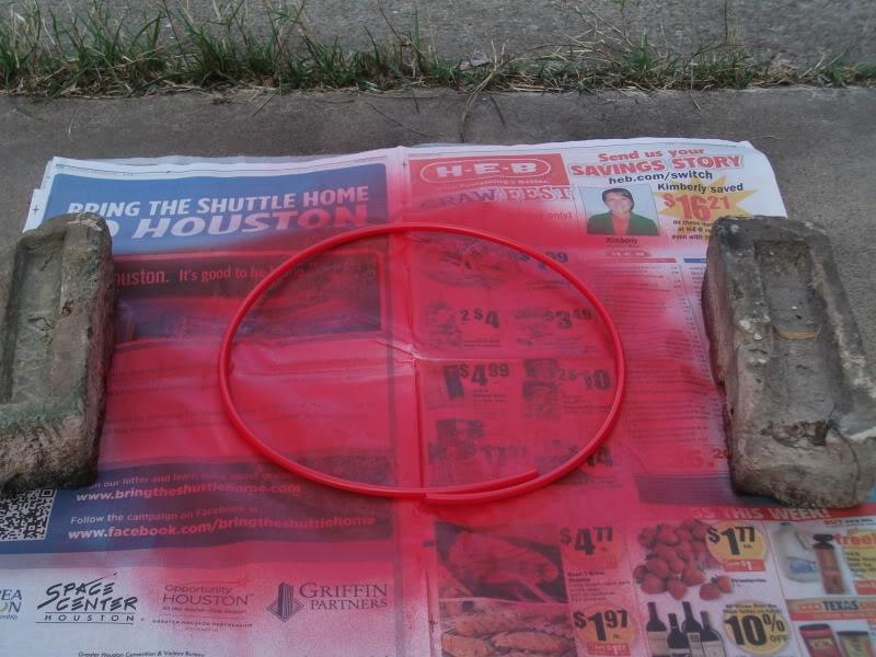
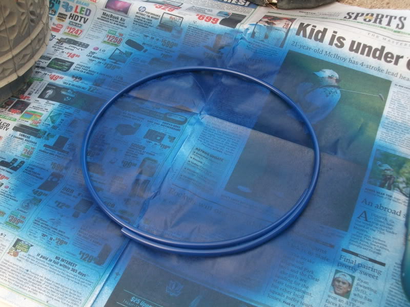
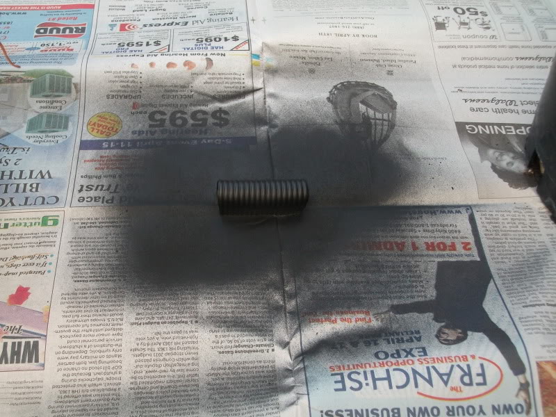
Vinyl spray paint (meant for touching up the interior of your car) works BEAUTIFULLY.
A quick run to the dollar store yielded some good finds.
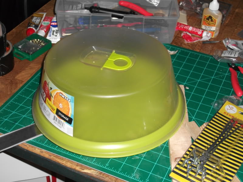
For the cyclotron, the diameter at the top happens to be exactly the right size.
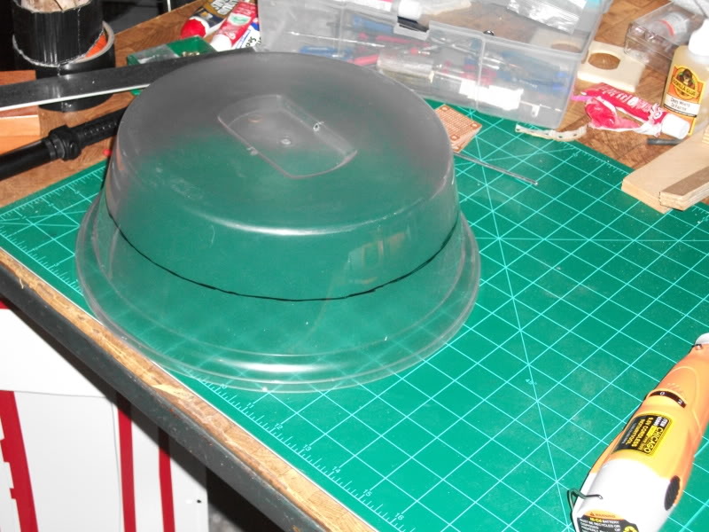
It’s a little tall, so…
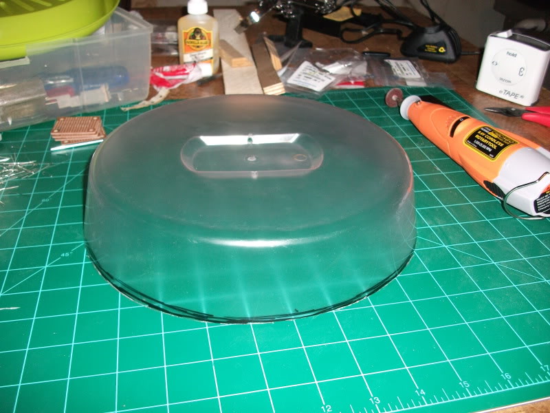
Ah, much better.
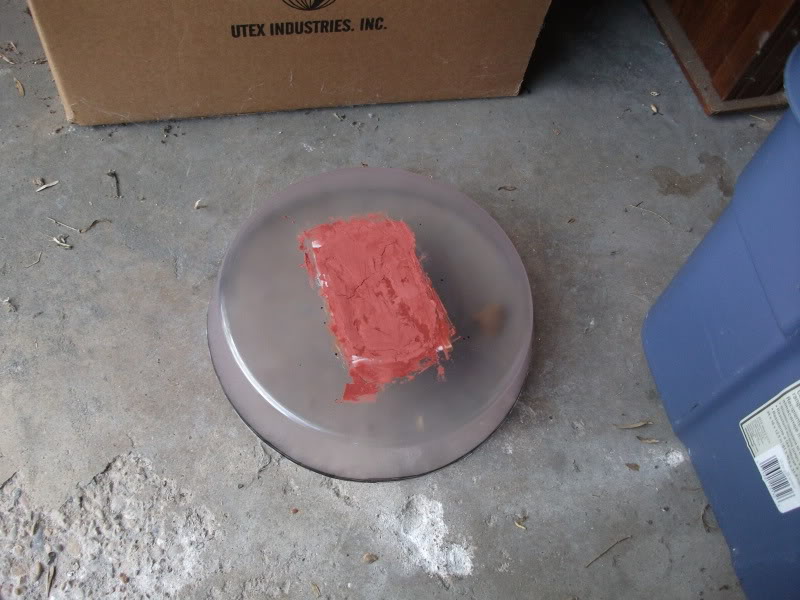
It also had this annoying dip in the middle, so I cut it out, backed it with some styrene from a for rent sign, and patched it with Bondo.
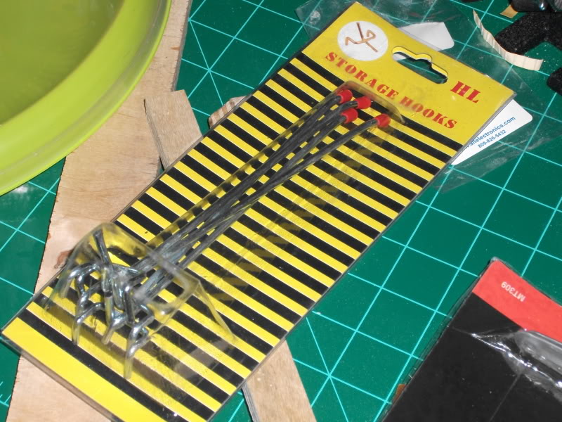
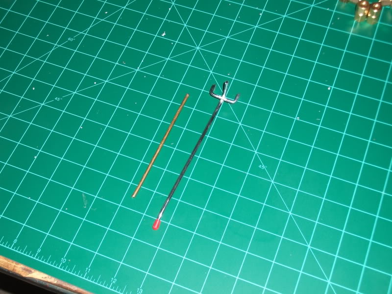
Saw these and realized they were a far simpler, cheaper solution to the Ion Rod. Cut them to size (bit of work with a dremel), hit them with some brass paint and…
Voila!
Angle brackets as a support for my custom-made bumper, which will be made from…
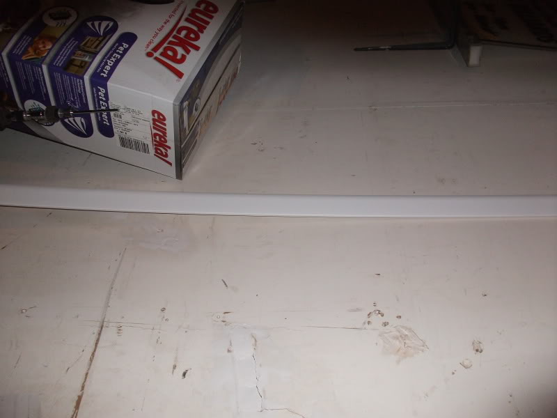
this. This did not come from the dollar store, it was about $3 at Home Depot. It’s a plastic/foam moulding, and it’s about 8 feet long. It’s bendy, but not as flexible as I was hoping, so it can’t just be bent into shape. I’m going to cut it down into sides and middle, held together by the brackets.
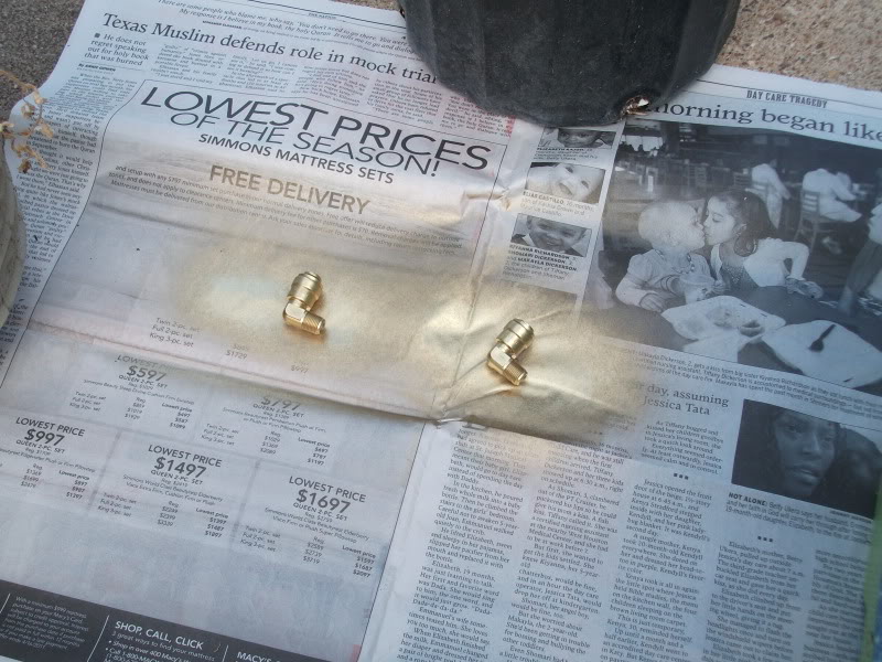
I got some plastic quick-connect elbows for the tubing, but I didn’t like them not matching the brass connectors I got for elsewhere, so…
I painted them with the brass paint, since I had it for the Ion Rod anyway.
I didn’t want to have to deal with finding the actual resistors, so I decided to make my own.
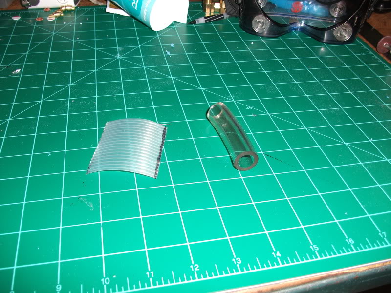
The piece on the left is a small bit I cut off of a ribbed drawer liner I found at Home Depot. On the right is a bit of tubing I have left over from my leg hose. By their powers (and some Goop) combined, I have…
Something that looks kind of like the Dale Resistor. Cut up another pegboard hook, Goop it into the center, and…
Tada! It’s kind of hard to tell from the pictures, but it is flat on the bottom, I formed the lining into a sort of C-shape around the tubing.
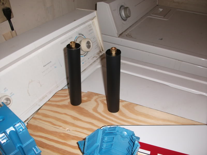
Here we have the PVC injectors drying.
Here they are assembled, with brass connectors attached for the tubing.
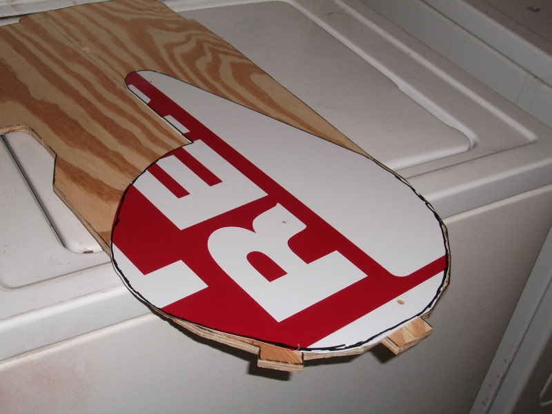
I cut out the top cover for the sync-gen.
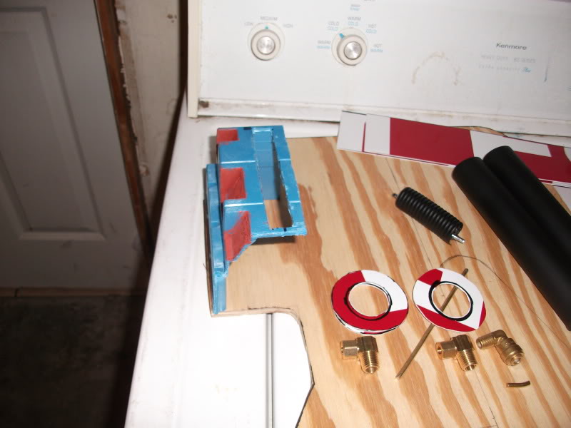
I liked Garree’s idea for the electrical boxes, but, alas they were too big. Trusty dremel can take care of that! Open sides will be covered with pieces of styrene. Those rings in the picture are the “washers” around the cyclotron lights.
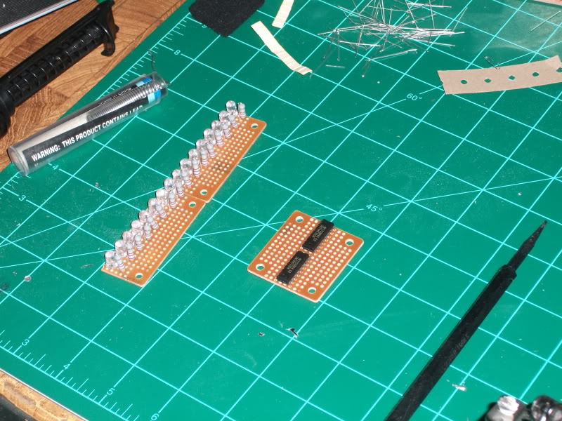
Here’s the bit of circuit for the lights in the Power Cell. Two shift registers on the right, so I can control all those with only 3 pins on the Arduino. I was doing a test fit, and I may have to remove one of the LEDs, which may be more accurate, anyway. I currently have 16 (partly because coding for that is slightly easier :p). I think there’s only supposed to be 15 (at least, that’s what I seemed to count in the reference pics I could find), but I couldn’t seem to find that number anywhere.
EDIT: OK, I found it, it is indeed 15. Looks like that extra light is coming off.