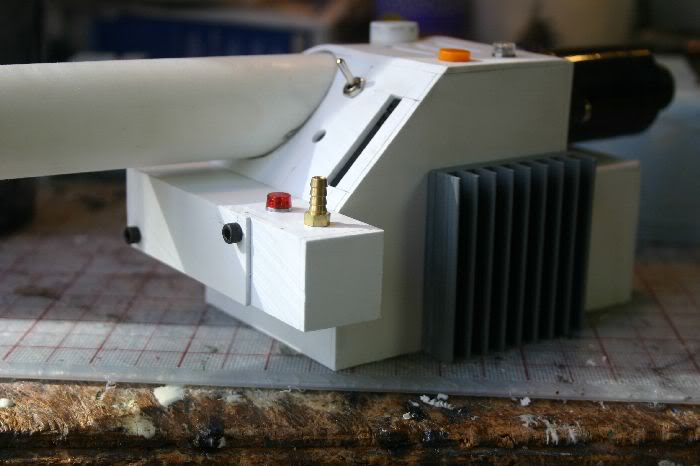
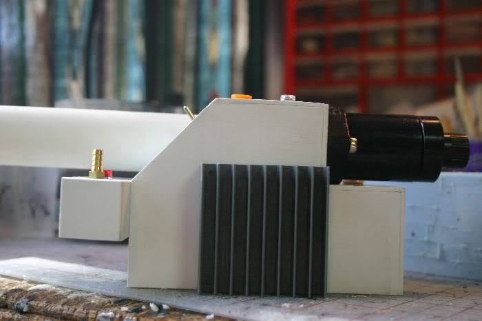
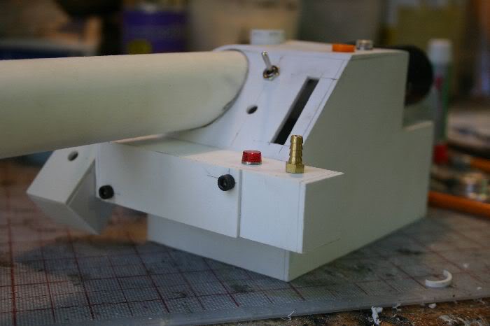
So TJ released V1 of his thrower plans a few months ago. A few people have commented to him that they found a few problems with them but no one could give any concrete feedback. I made an initial test build based off the plans a few months before they were released as a quick check but the dimensions have since changed. Being in need of a thrower and finally having some free time I figured it was time I built one and hopefully figured out what the problems with the plans were once and for all.
In the test build thread people asked for a tutorial on working with styrene. I’m not entirely sure how to do that other than say “cut out the parts and glue them together” but I’ll see if I can eleborate. I started with the thrower body by printing off the three sheets that comprised the dimensions. To make things easier I went over all the sheets and converted as many decimals as possible to fractions. It’s a lot easier to find 7/8ths on a ruler than remember that .875 is the same thing. Once that was done I went about deciding what parts would be “on top” of other parts. Due to material thickness you have to subtract from the total dimension to get the actual cut size. I’m using .08 styrene for my build, I could have used .06 and just called it 1/16th (which is .0625) which would have simplified things a bit but I wanted to be as accurate as I could. Subtracting a “non-whole” fraction means I had a lot of wierd numbers to work with and a set of digital calipers was indispensible for the project. If you don’t have some I’d suggest picking up a set, they’re usually about $10 and worth every penny.
So with the plans worked out it was time to start cutting styrene. Since people wanted a tutorial I guess I should add a quick talk about styrene. Typically when not using power tools for the job, styrene is cut with the “score and snap” method. This means laying a metal straight edge along the line you want to cut, running a sharp knife (typically an exacto with a #11 blade) a few times down the line until you’re about halfway through then bending both sides of the styrene back away from the cut thus “snapping” the pieces apart. This cuts down on the amount of time you spend cutting thick parts but does have some draw backs. Typically the cut isn’t clean, the following pictures show common problems of mushrooming, angling and cracking:
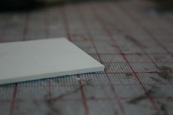
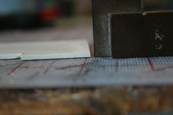
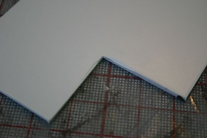
“Mushrooming” happens when the blade edge forces the plastic out of the way. It makes your cut edge thicker than the rest of the piece and if not trimmed will keep you from making a square edge. This is easily knocked down with the flat of a blade and/or some sand paper, just be careful not to round the edge over too much. Angling typically happens on thicker pieces of styrene. If you don’t score deep enough into the plastic or push too hard with the blade, when you snap it it will break on an angle instead of perpendicular leaving you with a non-square edge. A combination of cutting lightly repeatedly and a little oversize then sanding should mitigate the problem. Cracking typically happens on corners and circles. When snapping the score the presure in the corner isn’t directed and the plastic tears. To prevent this just score the plastic on both sides first or else cut all the way through.
On to the actual build, here’s the tools I used:
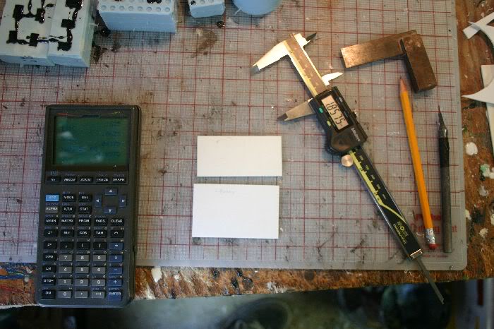
Only thing not shown is a metal straight edge. As I cut out parts I’d label them and set them in a seperate pile so I wouldn’t accidentally cut them up for new parts.
The final pieces:
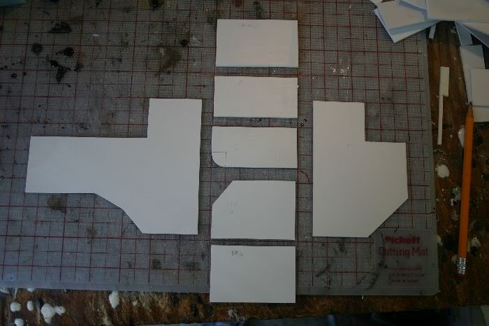
I had to fudge the “face plate” and compound curve of the fold over as working out exact dimensions would be a pain of geometry. I did have to work out the quarter diameter of the curve (.7854 if anyone cares) to ensure the top would be long enough but it’s simple math.
Assembly:
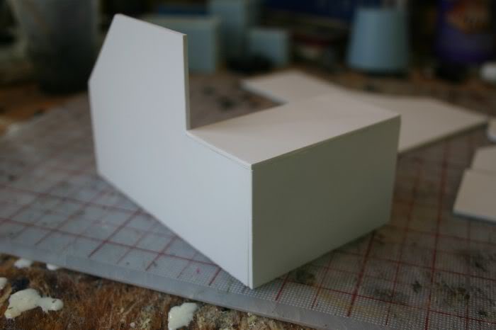
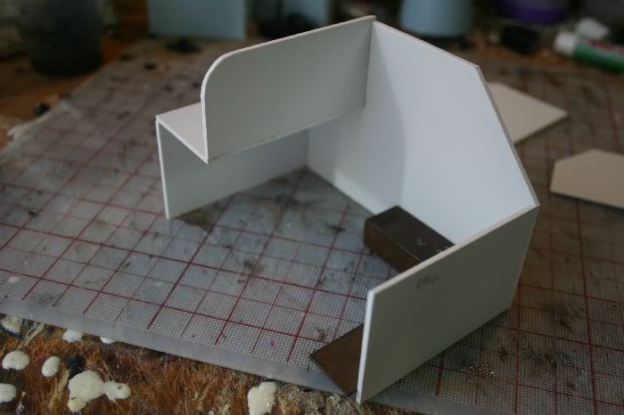
The parts were glued together with superglue. The minisquare kept them more or less square.
For the curve I used a heatgun to carefully bend the plastic into shape.

I actually wound up with a bit of a dip in the center but baring making a forming jig it’s about as good as I could expect it.
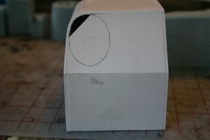
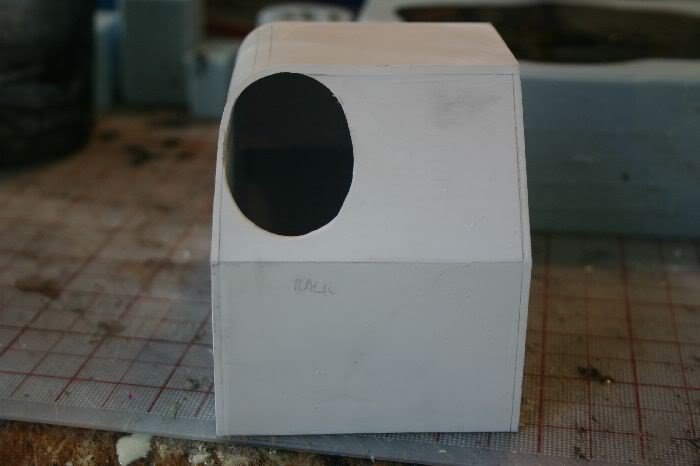
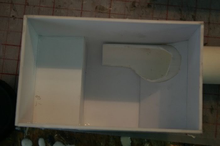
After trimming the excess plastic from the edges I marked out the location of the handle hole with the convinient template TJ added then trimmed it out with an exacto knife:
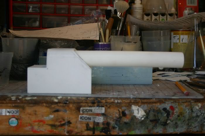
For the rear handle I used a 1.25" sink drain tube:
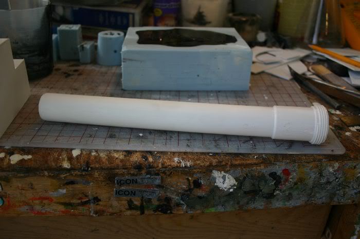
The larger section was cut off and the part going into the body was trimmed down:

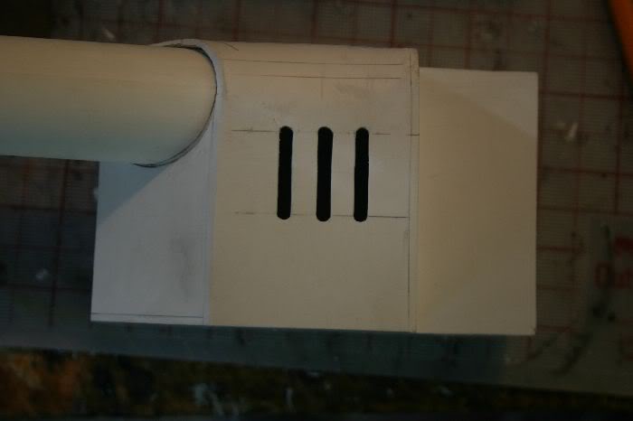
I marked out the vents and cut them out with a hand drill and exacto:
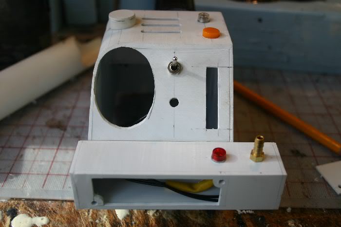
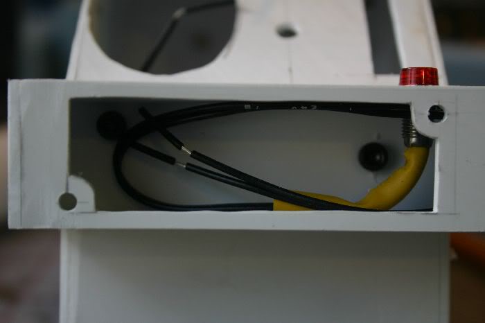
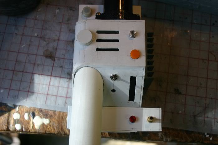
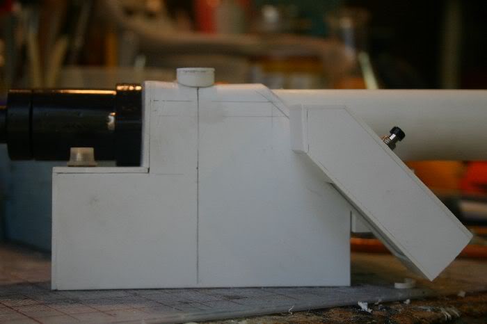
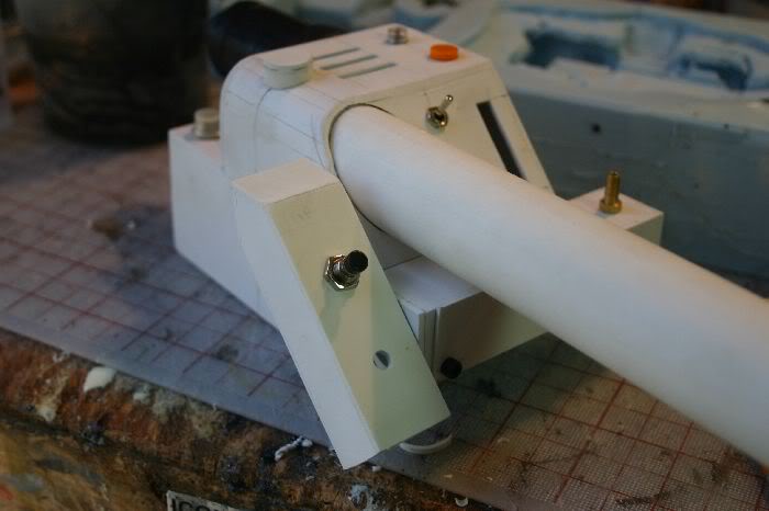
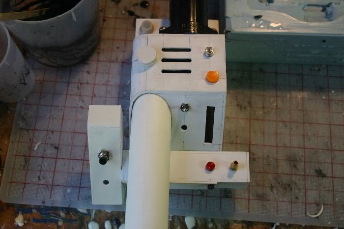
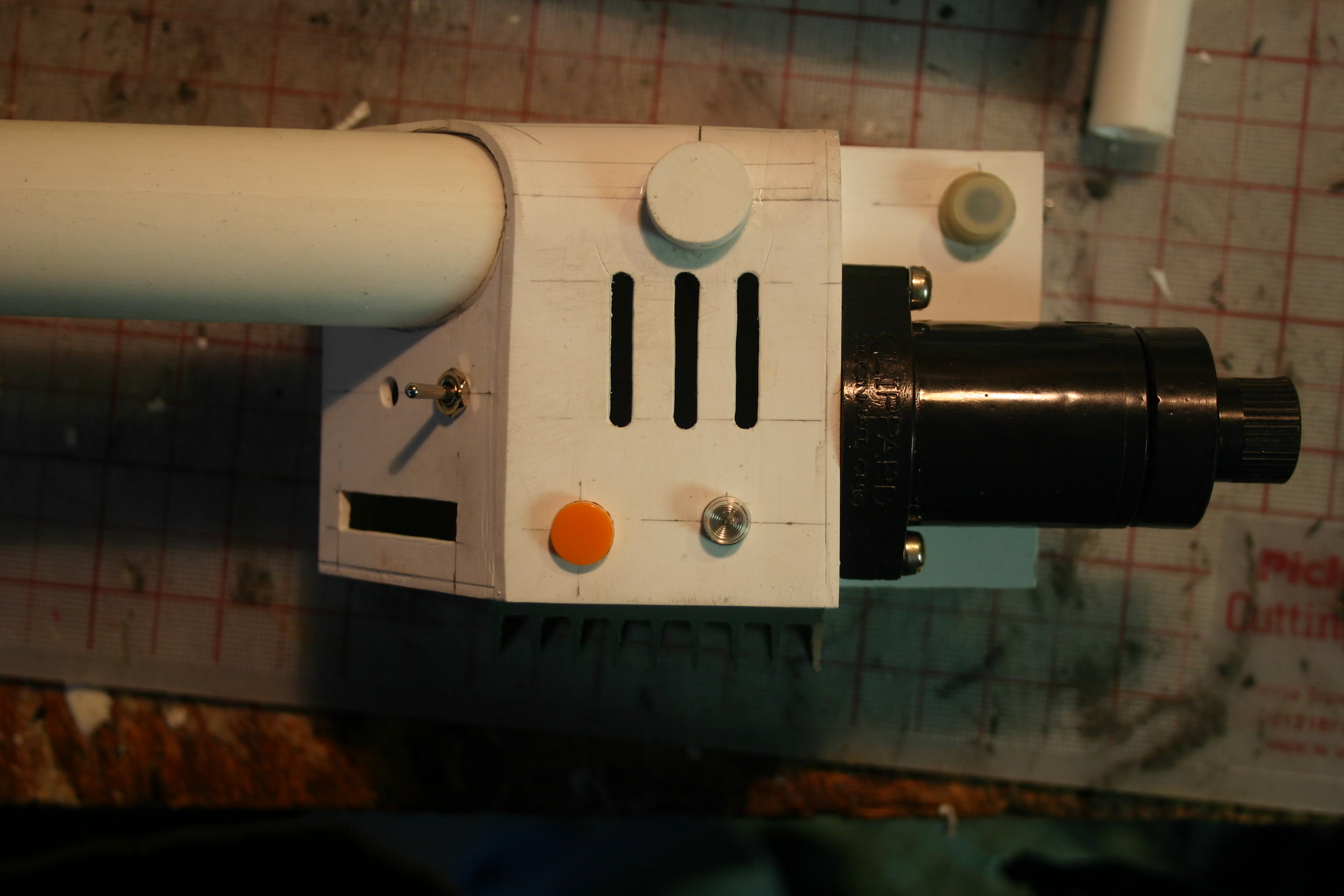
The various holes for lights, switches, Clippard and the bargraph were drilled. This is one place were I found a few errors in the plans. The holes for the toggle switches should be 3/16" instead of 1/4" and the hole for the hat light next to the vent should be .38" instead of .40". These are obviously minor problems though.
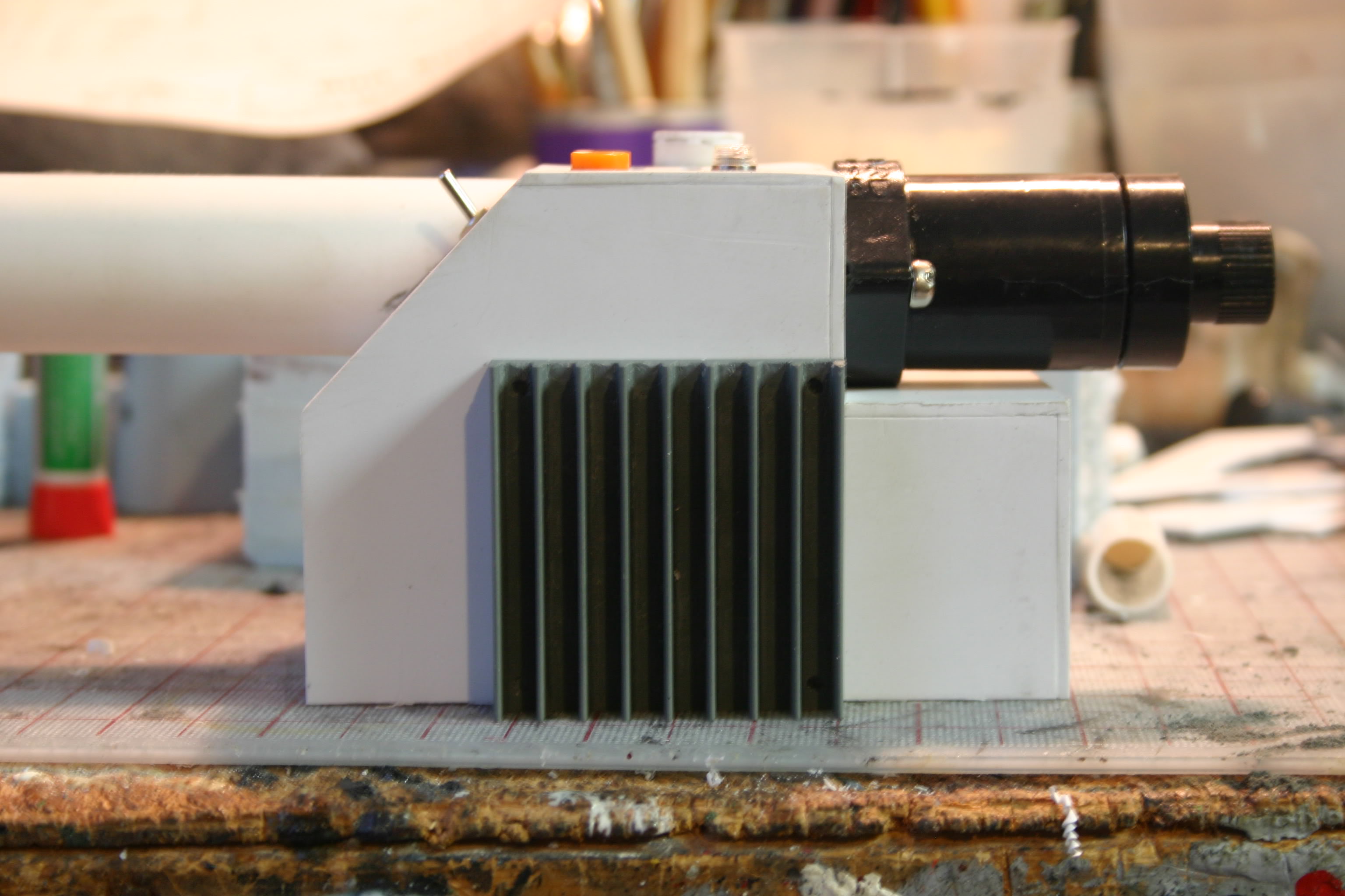
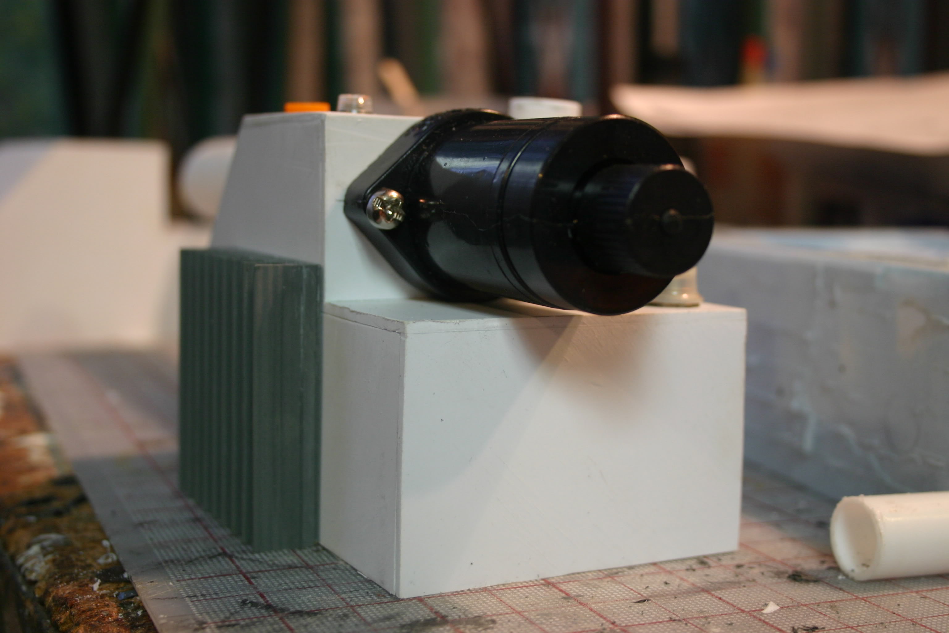
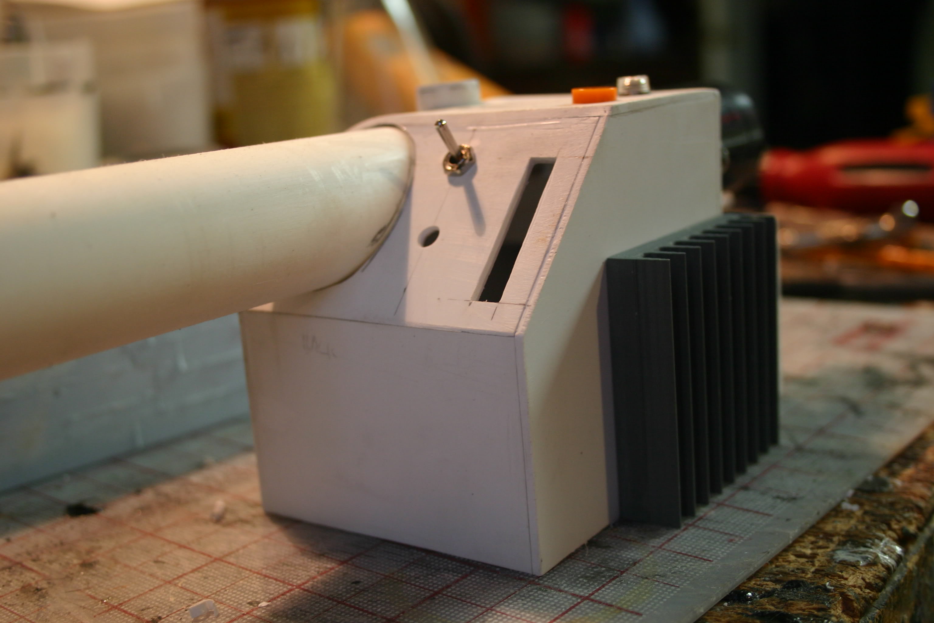
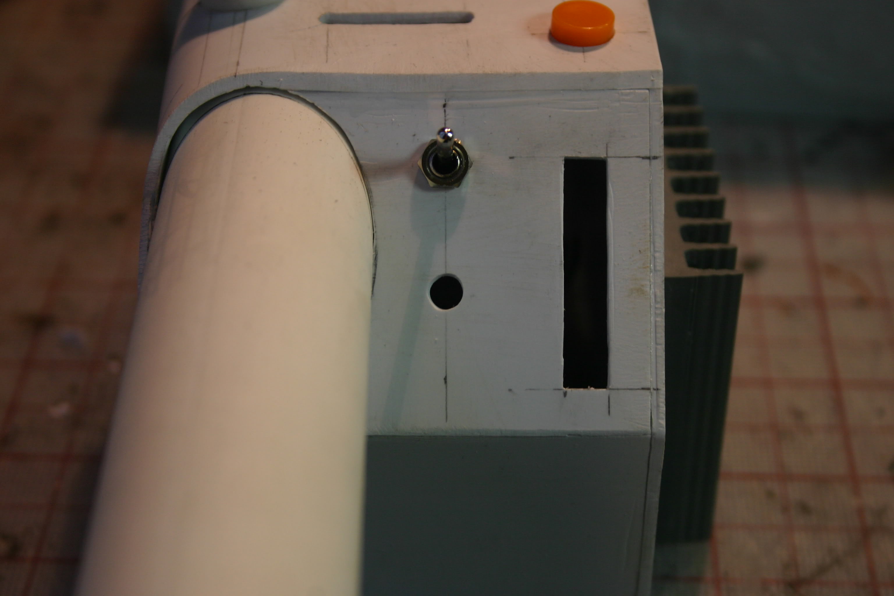
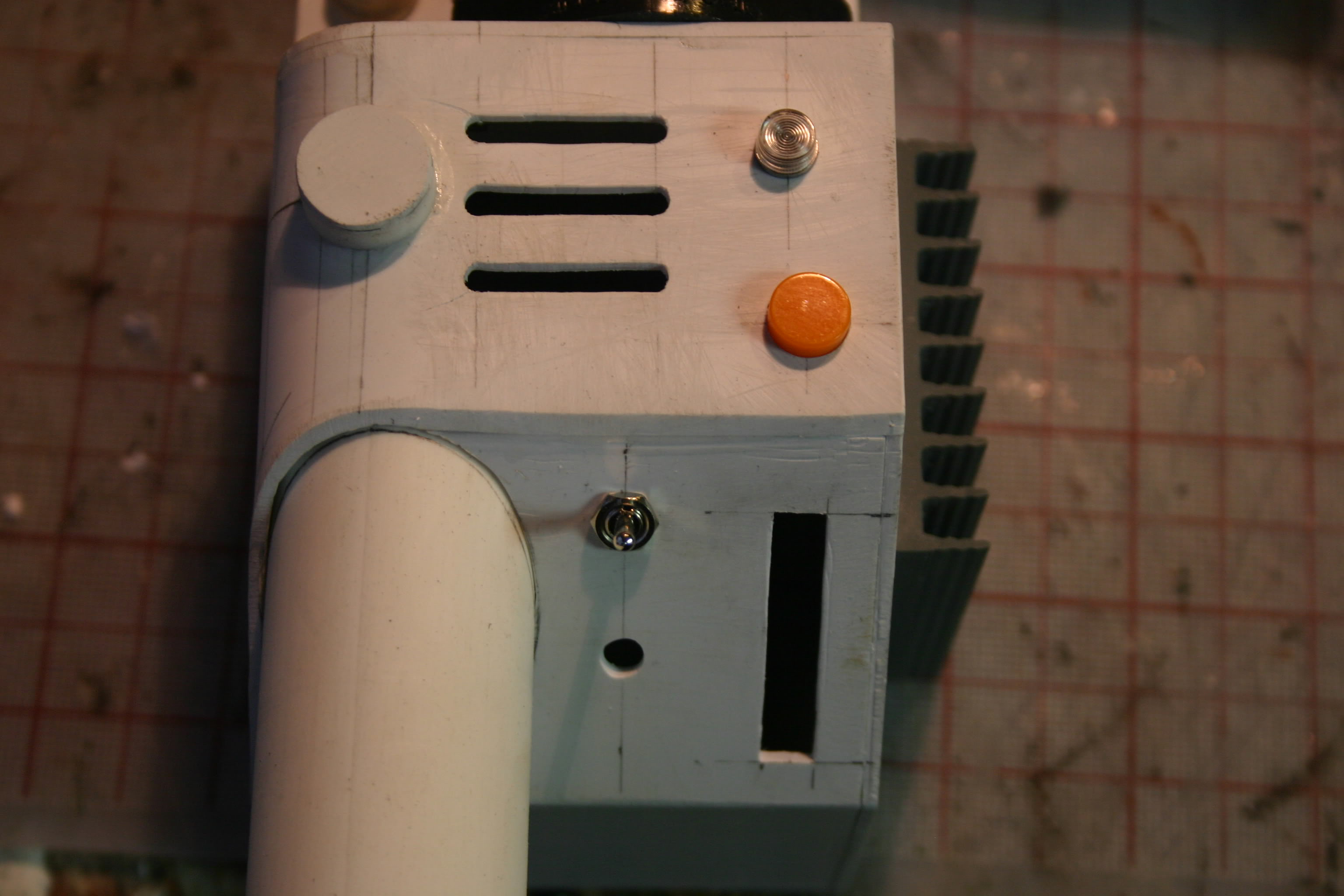
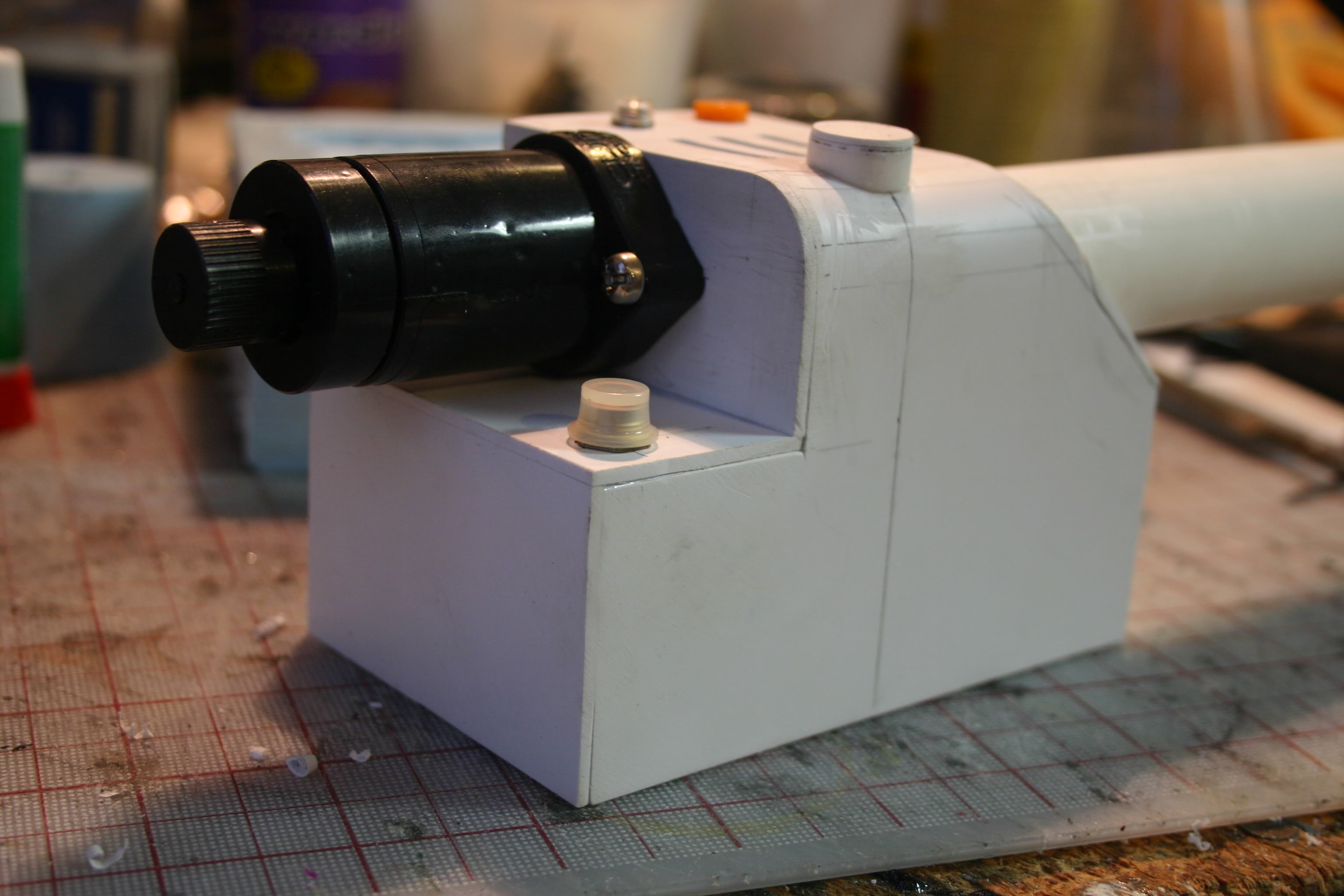
The post for the top knob was made from a krazy glue tube and some styrene as it’s the only 5/8" tube I had on hand.
Continued in part 2…