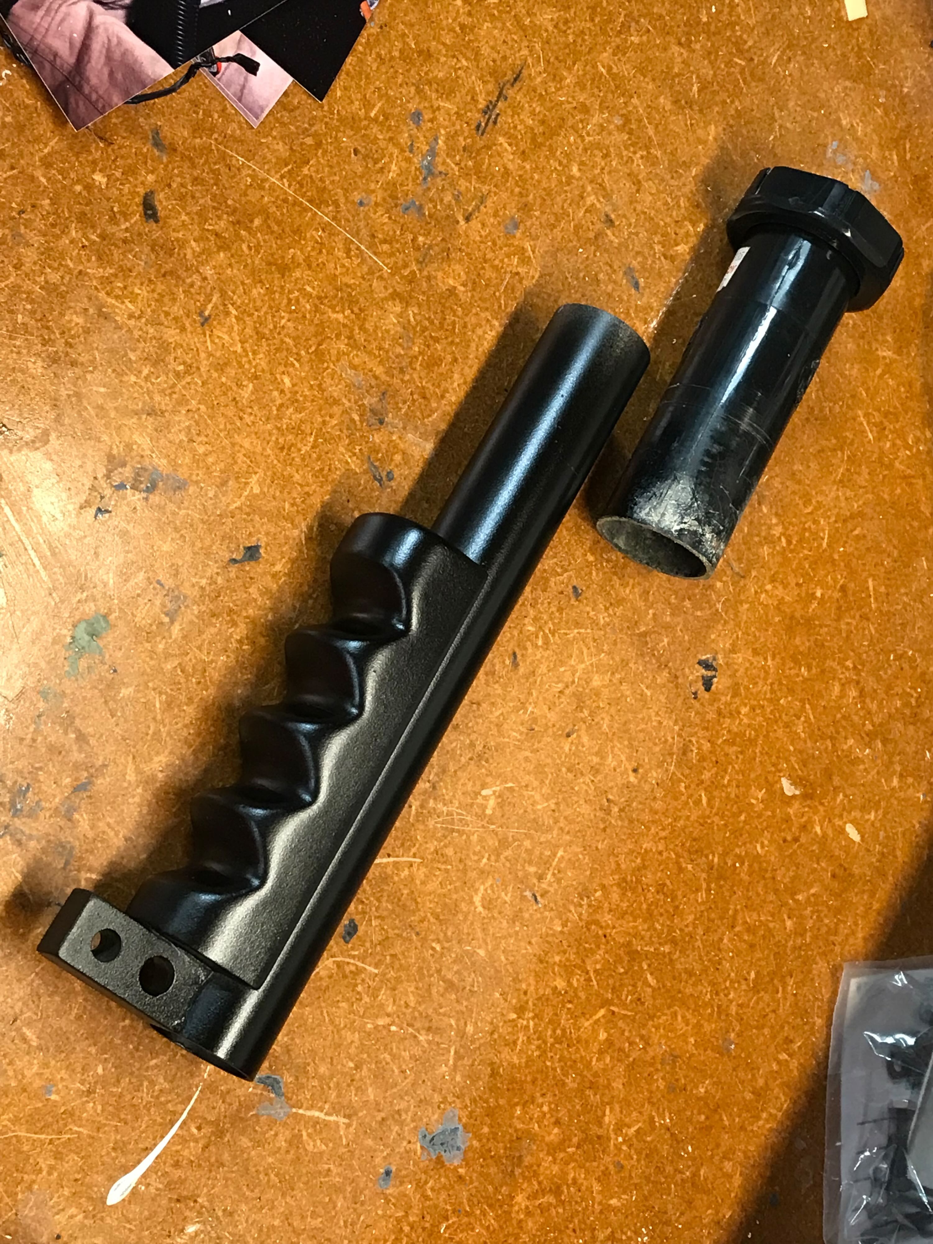
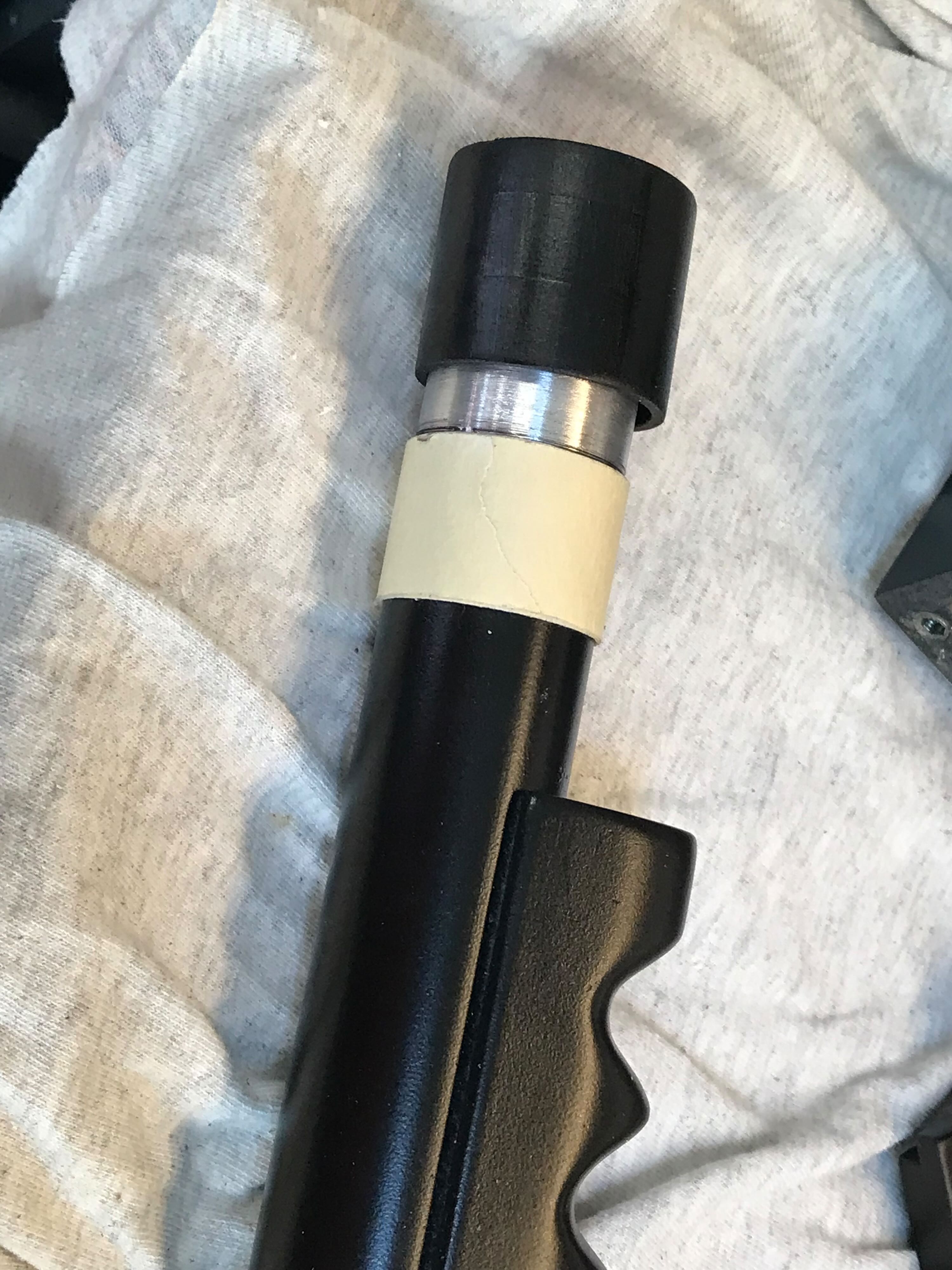
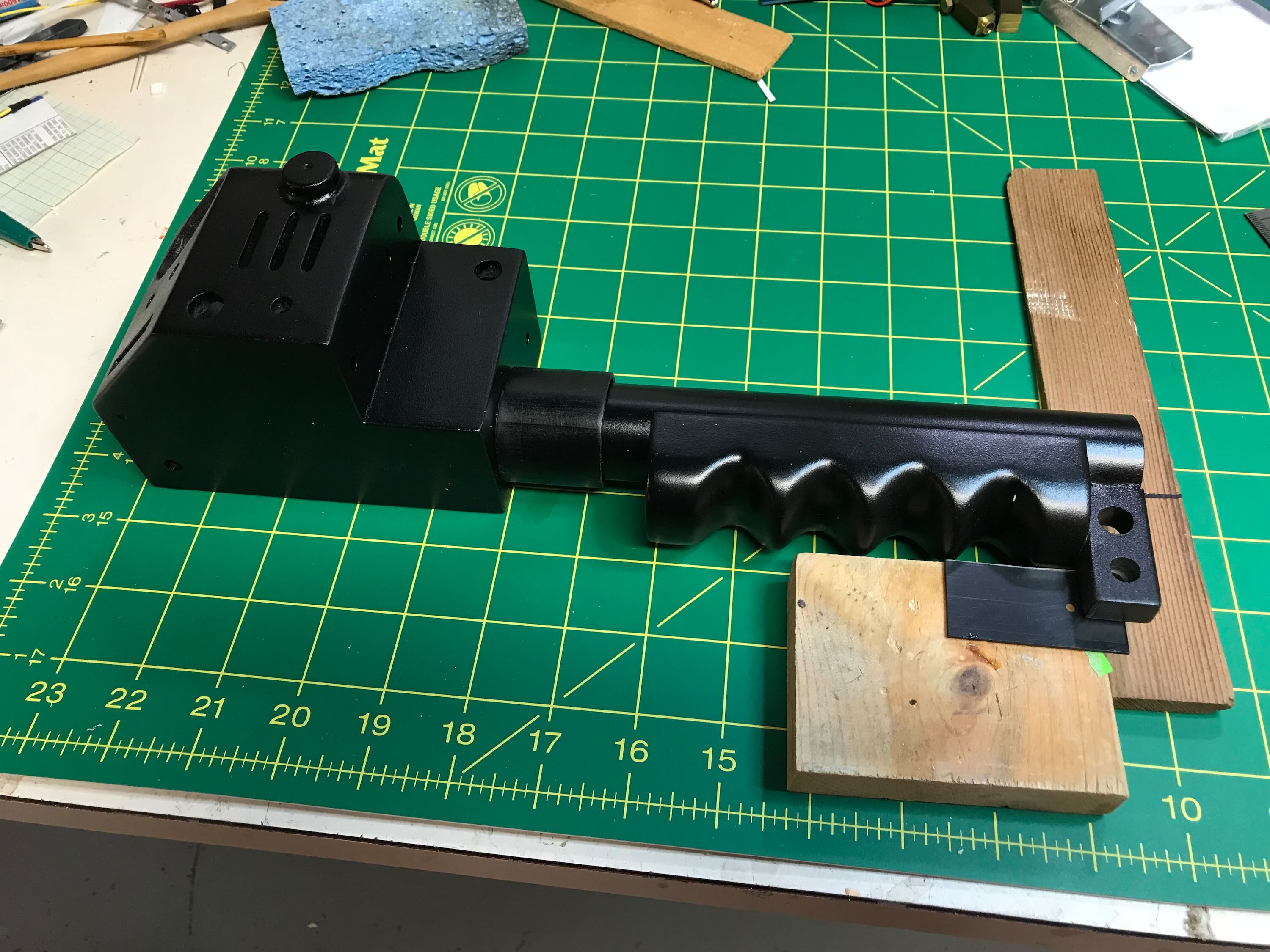
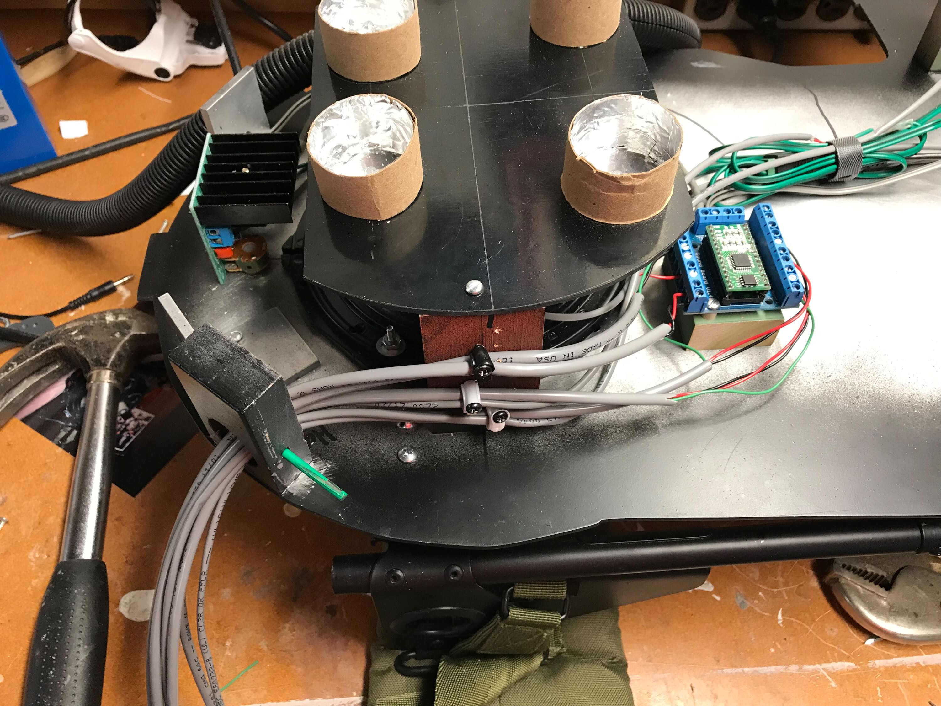
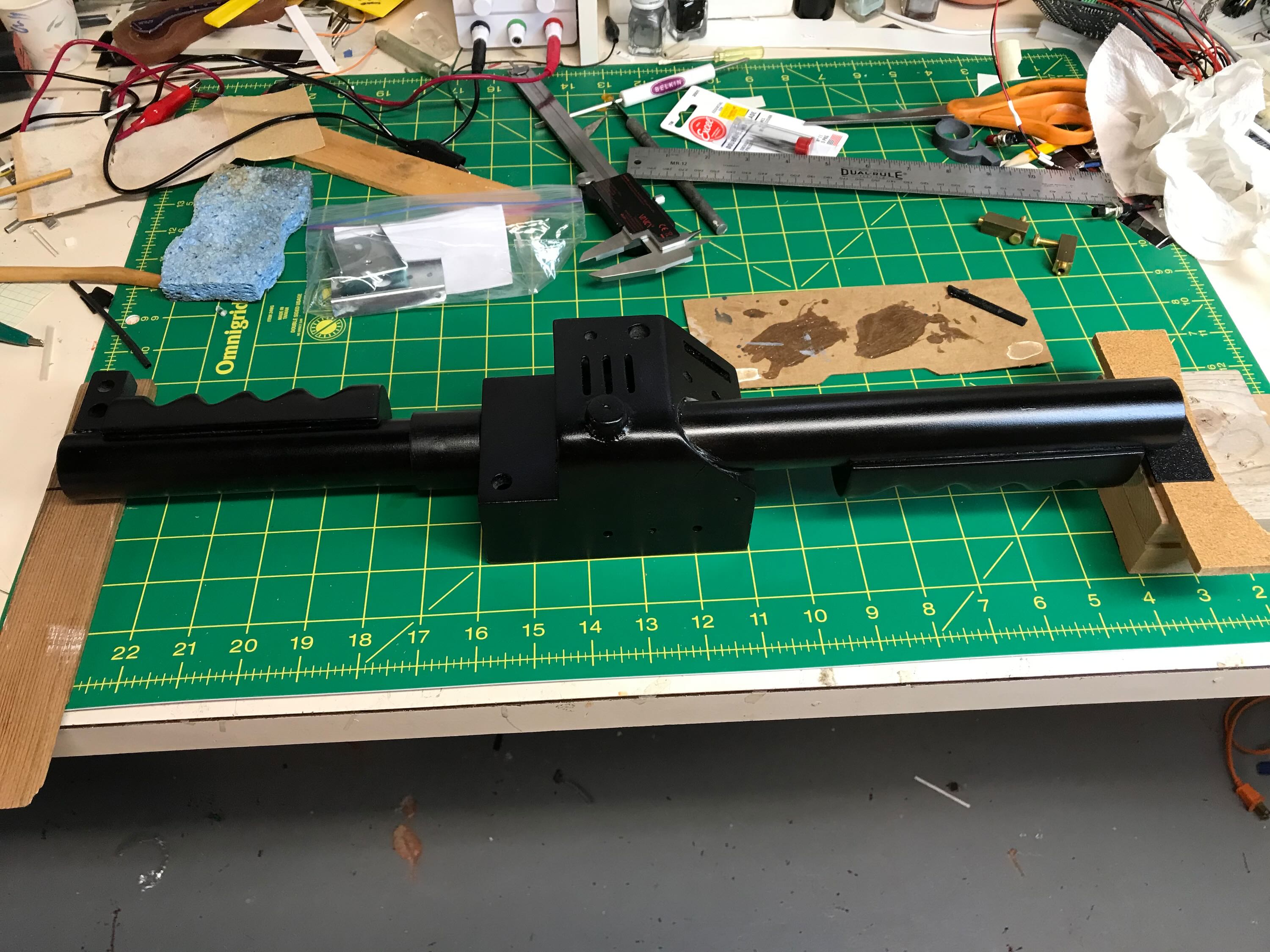
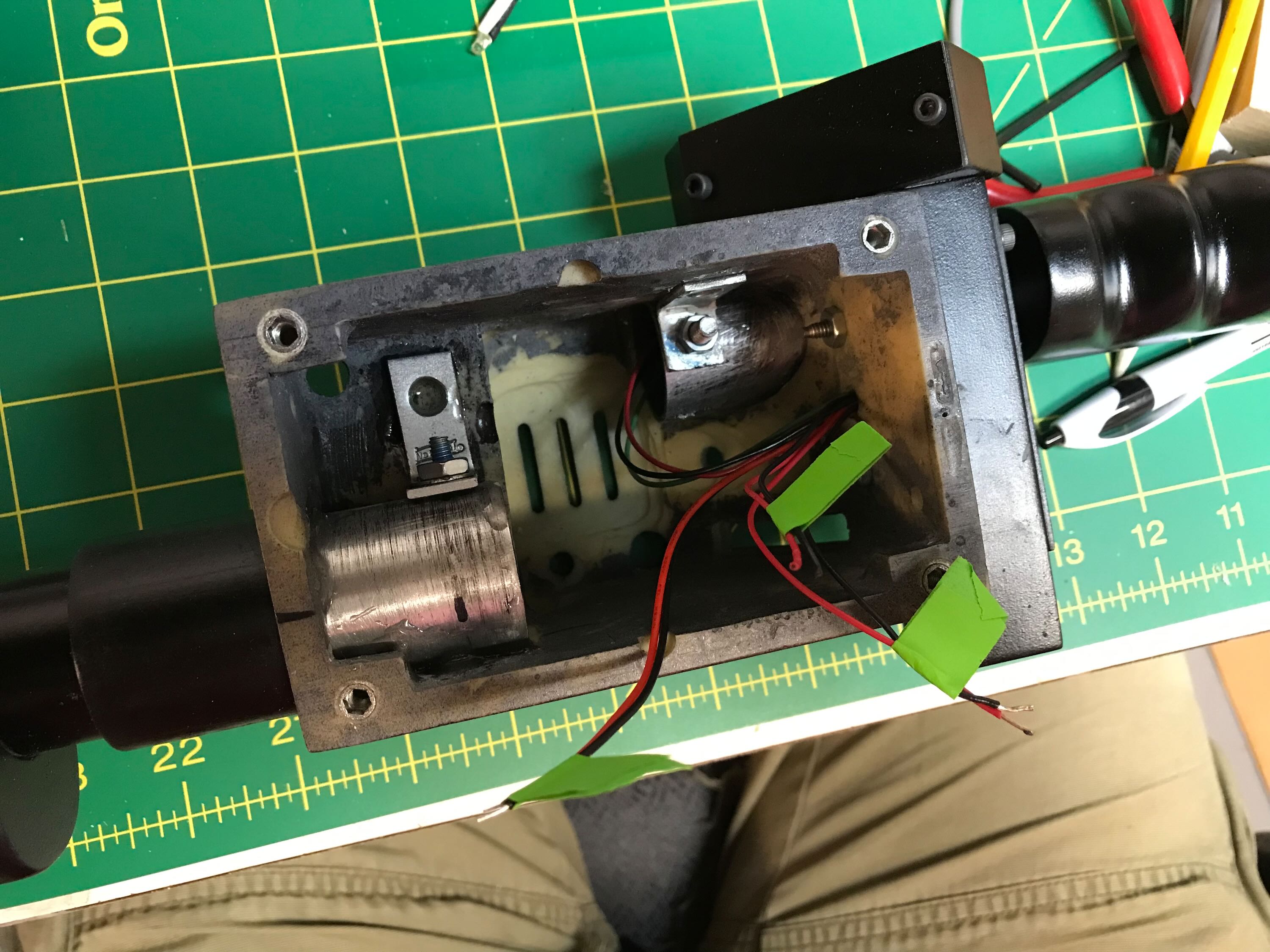
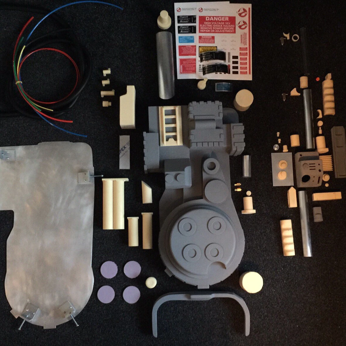
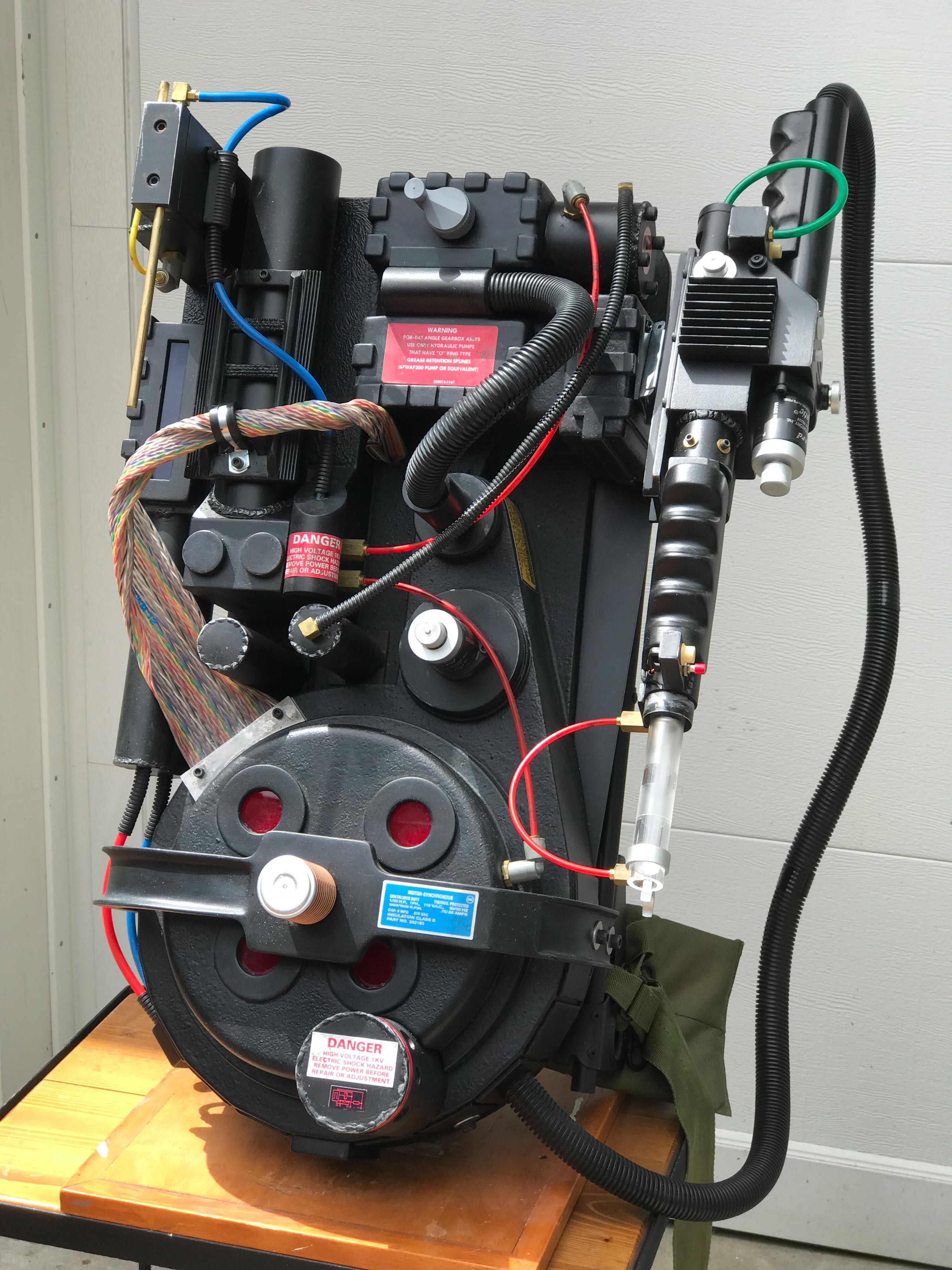
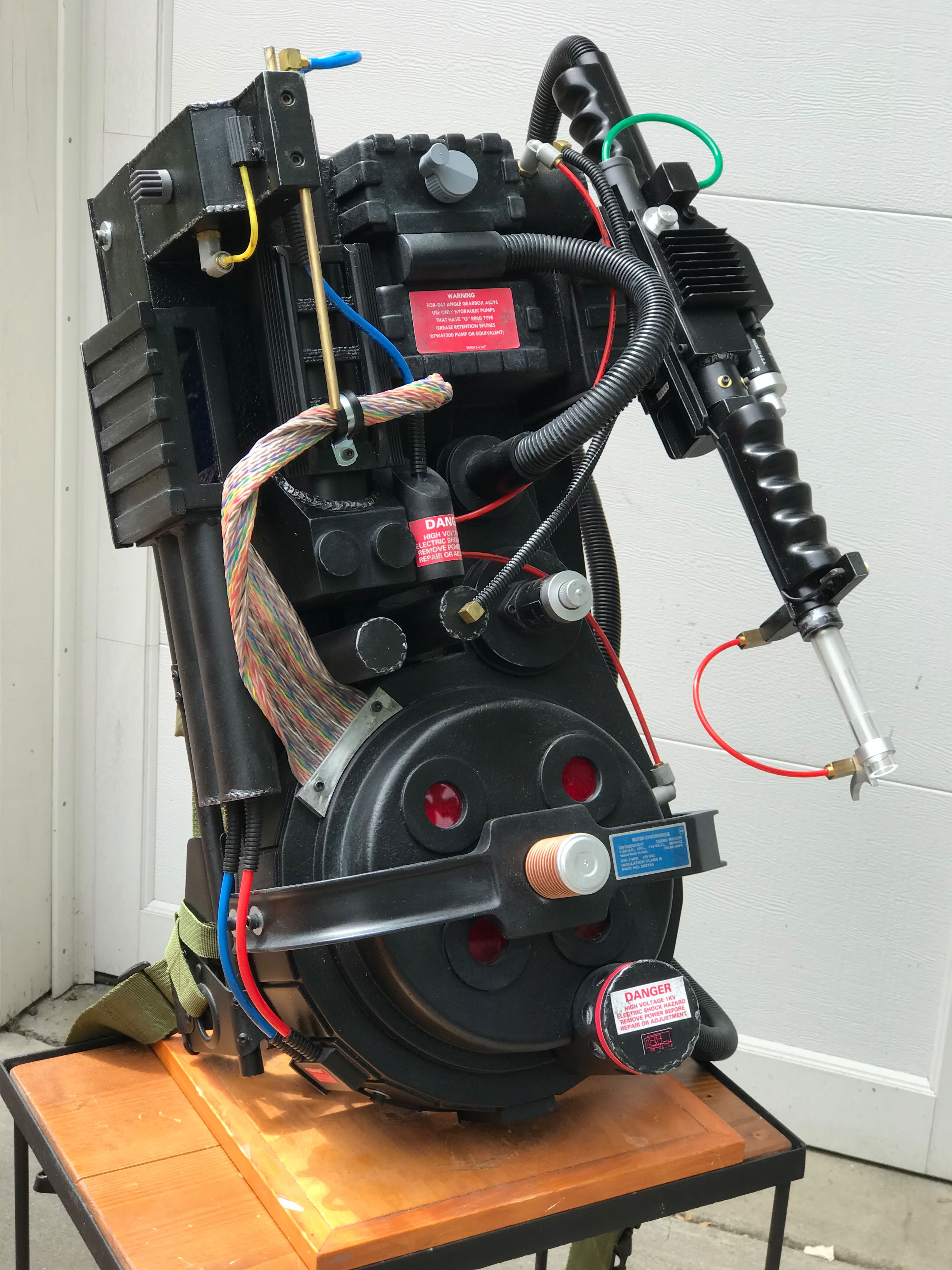
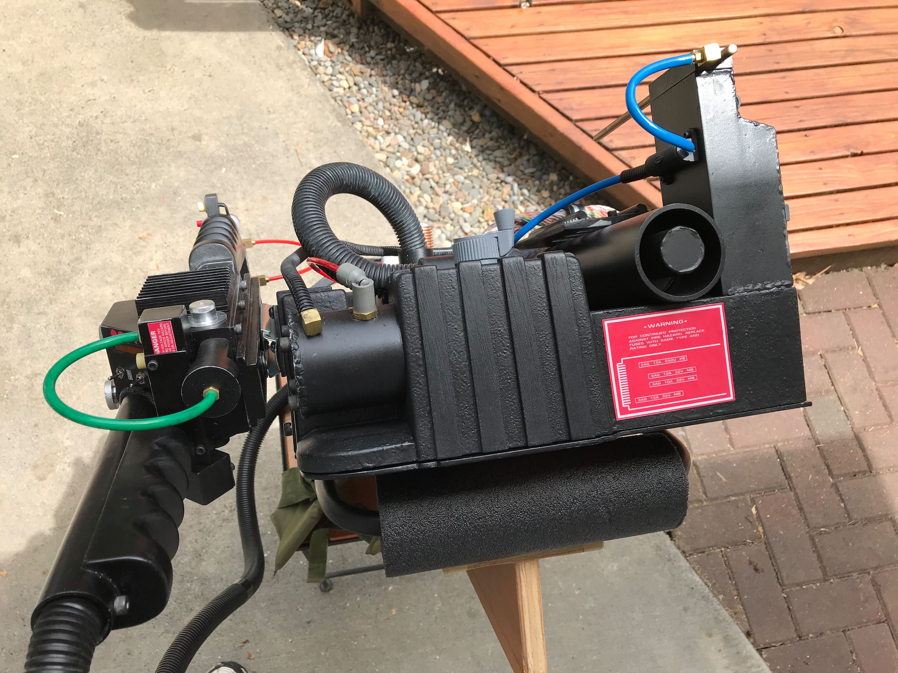
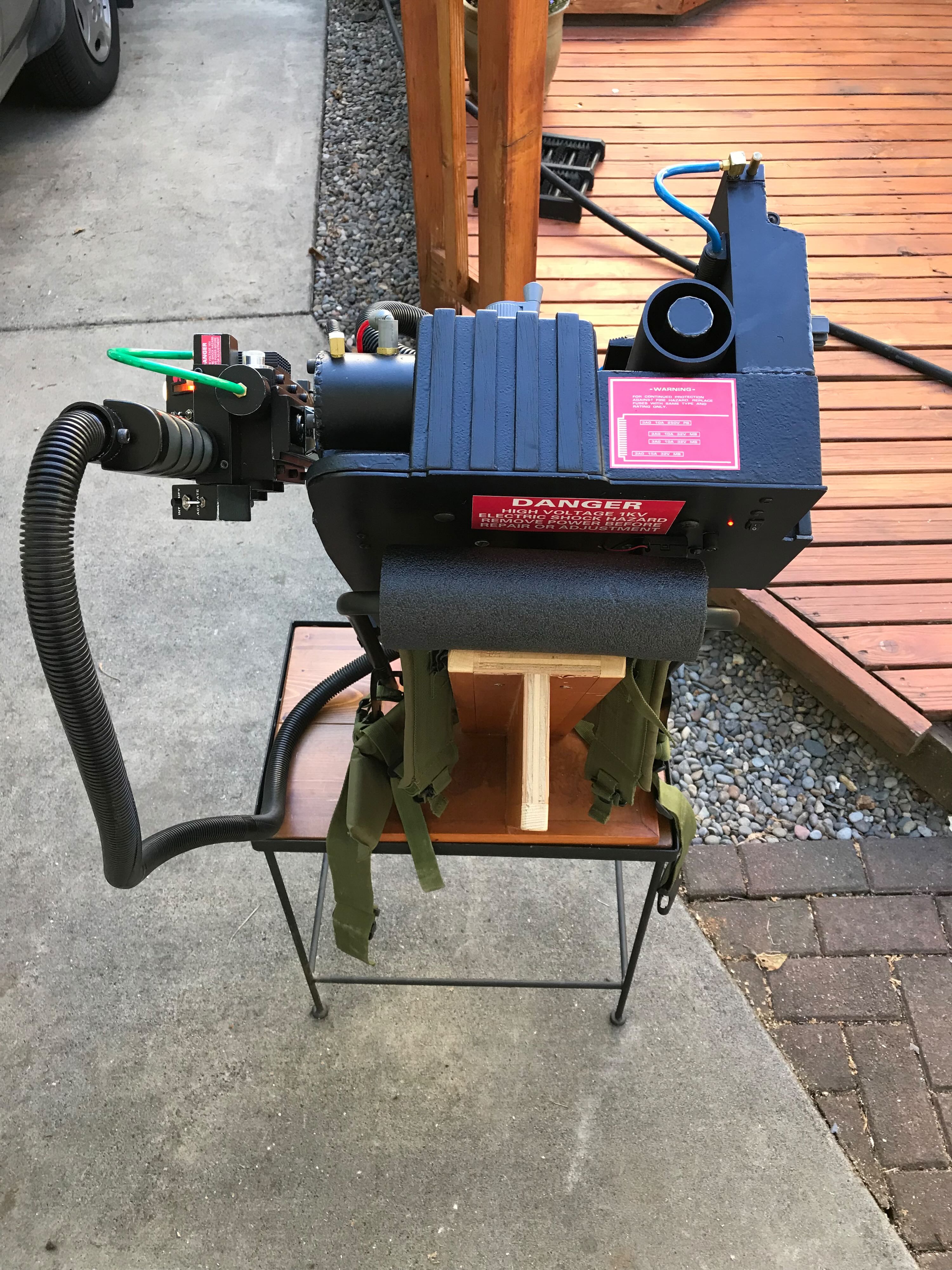
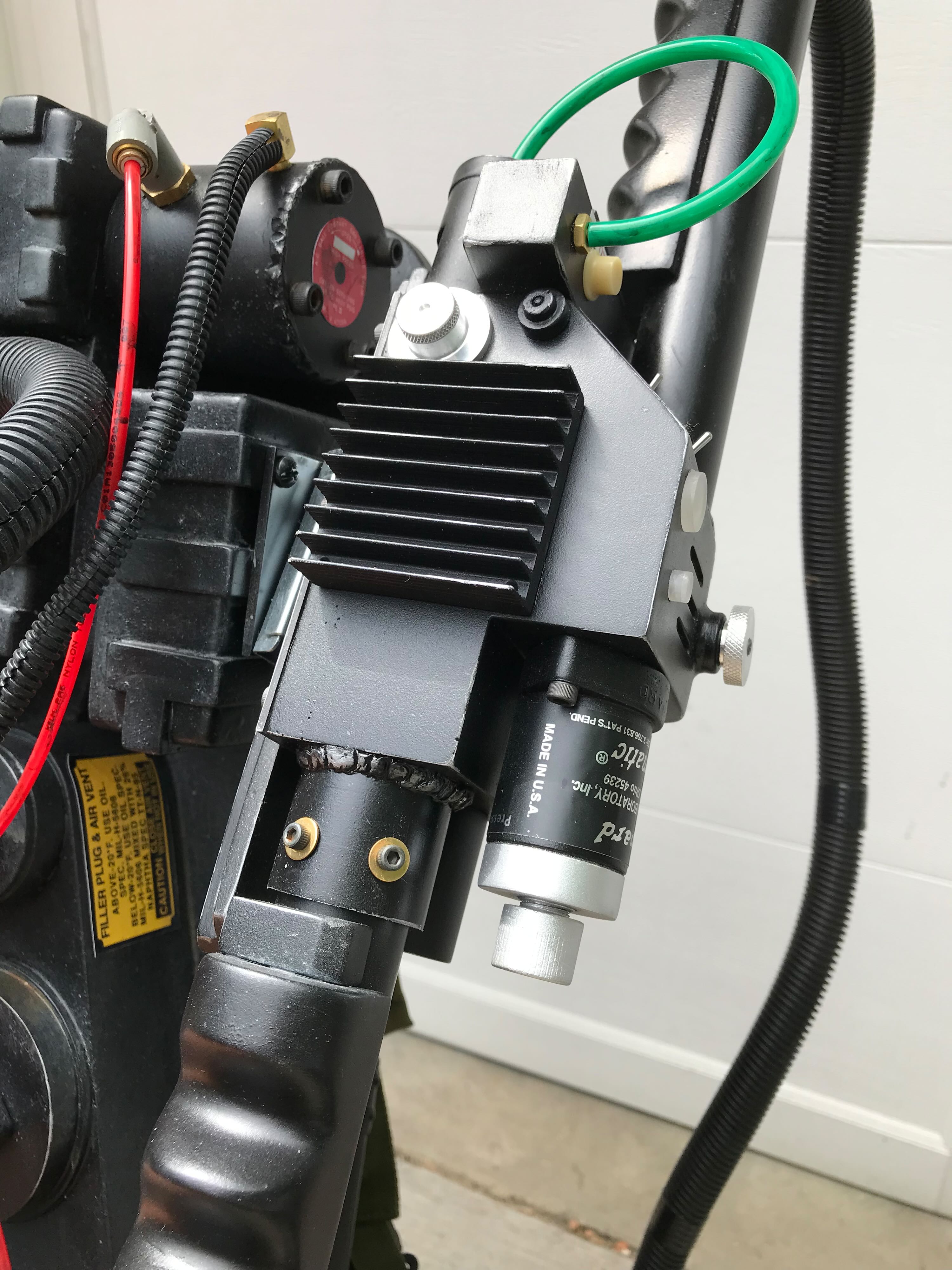
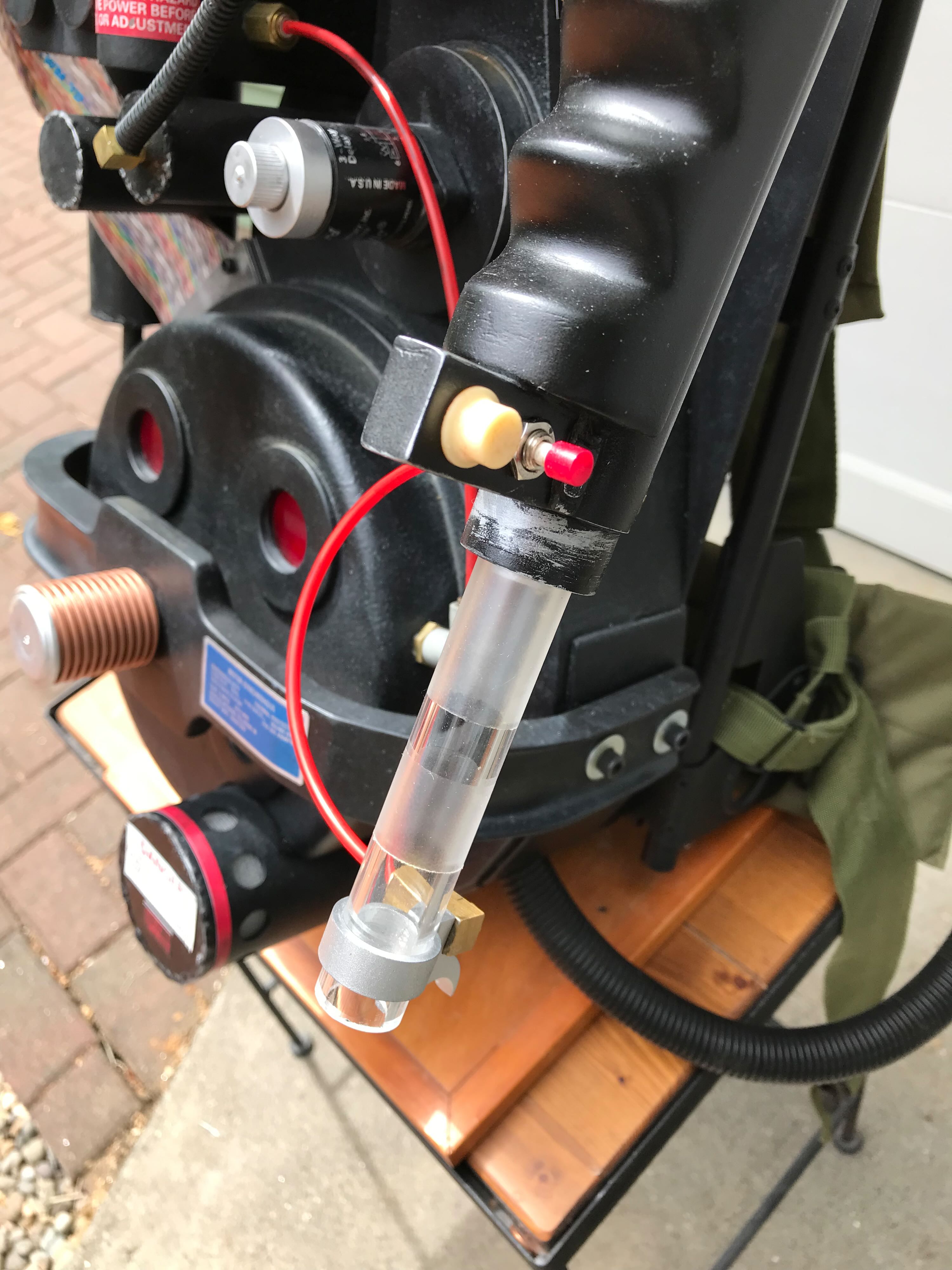
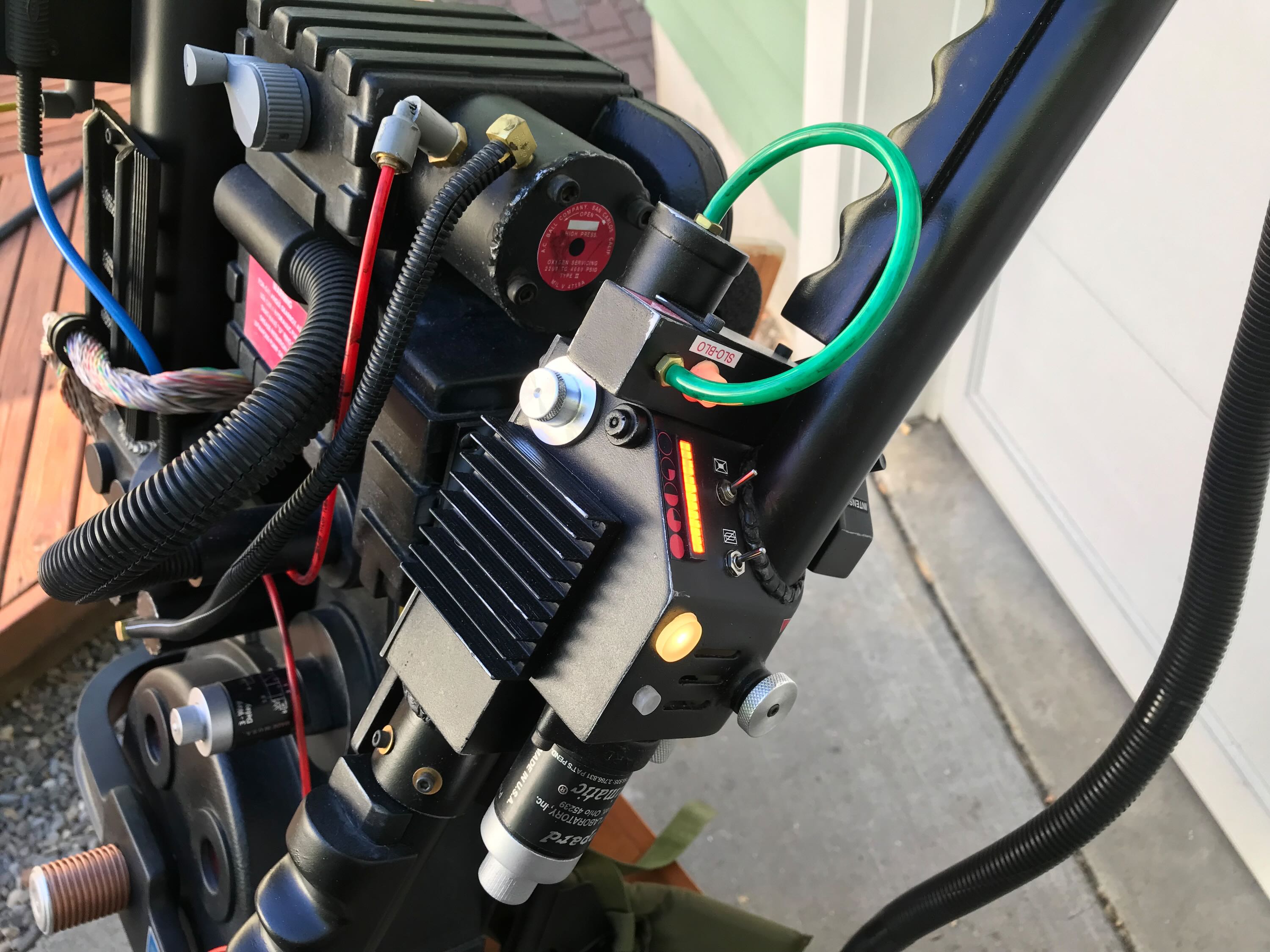
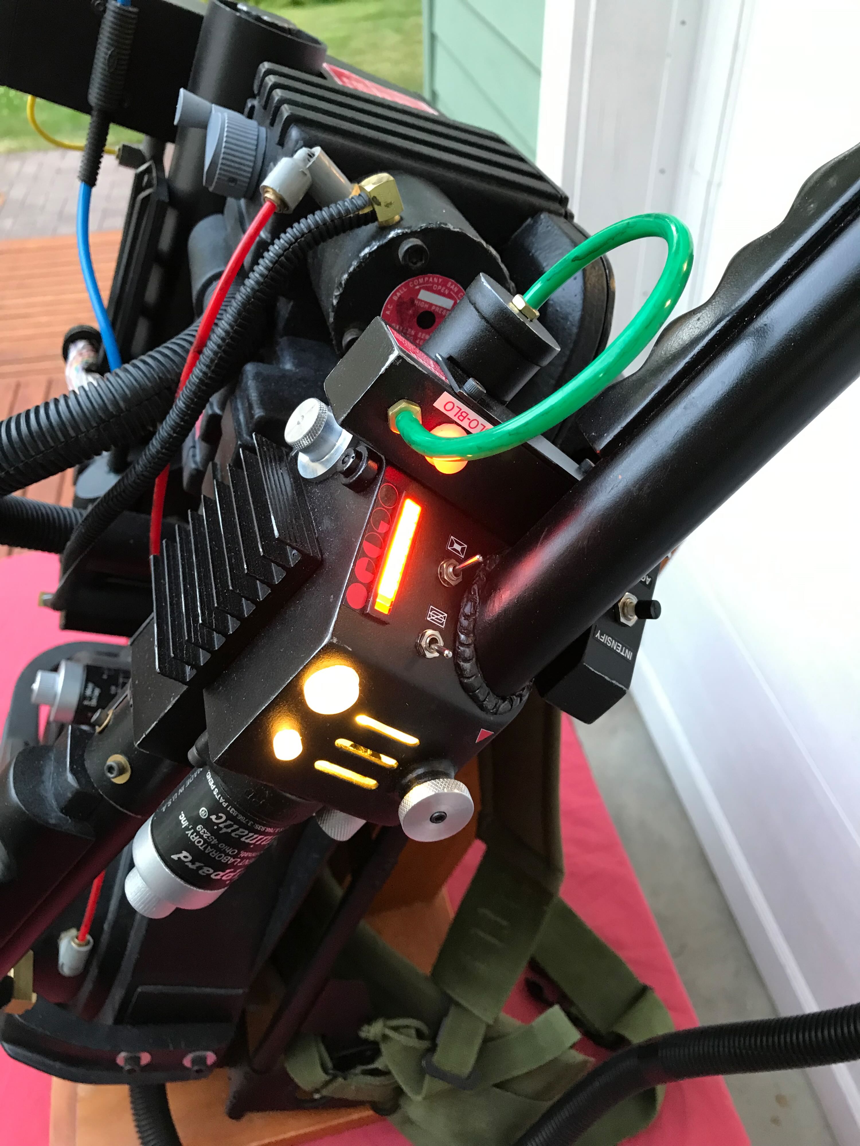
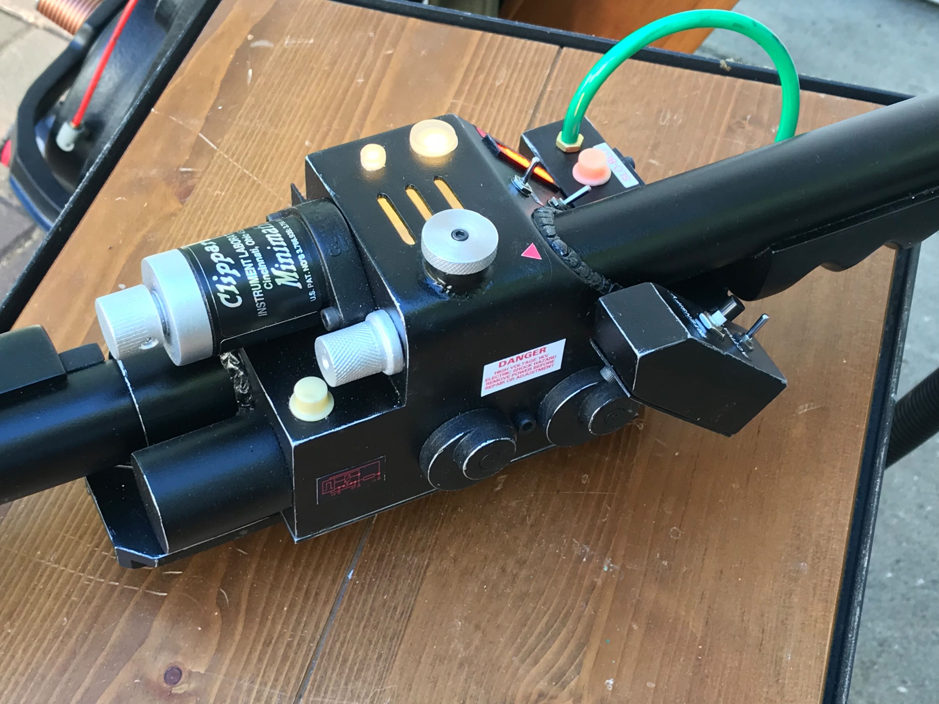
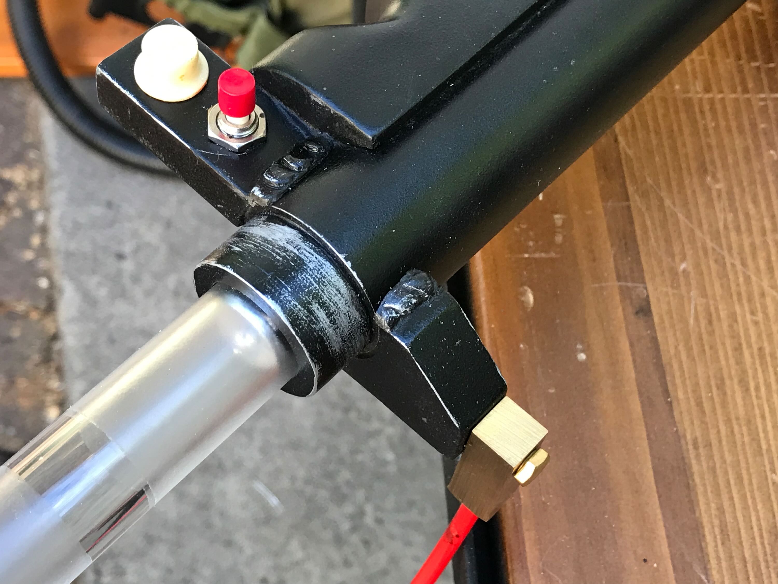
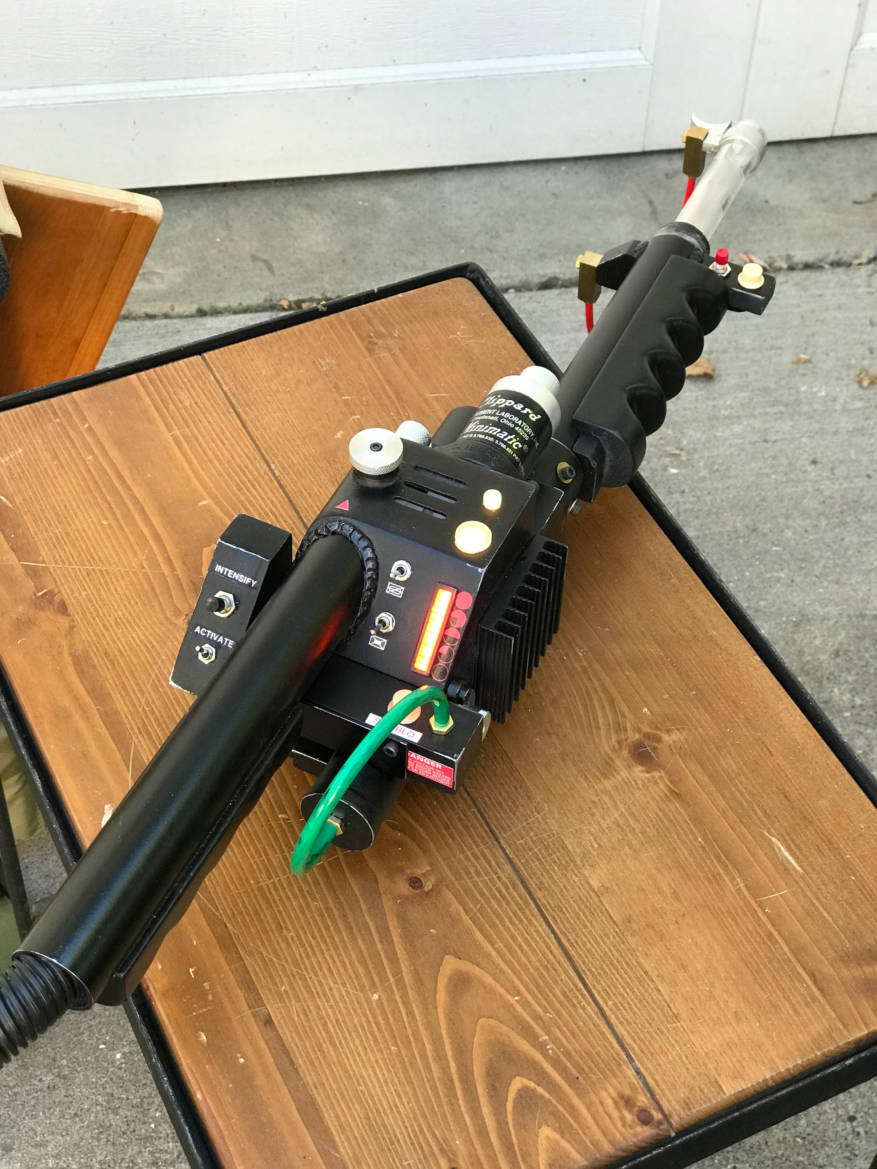
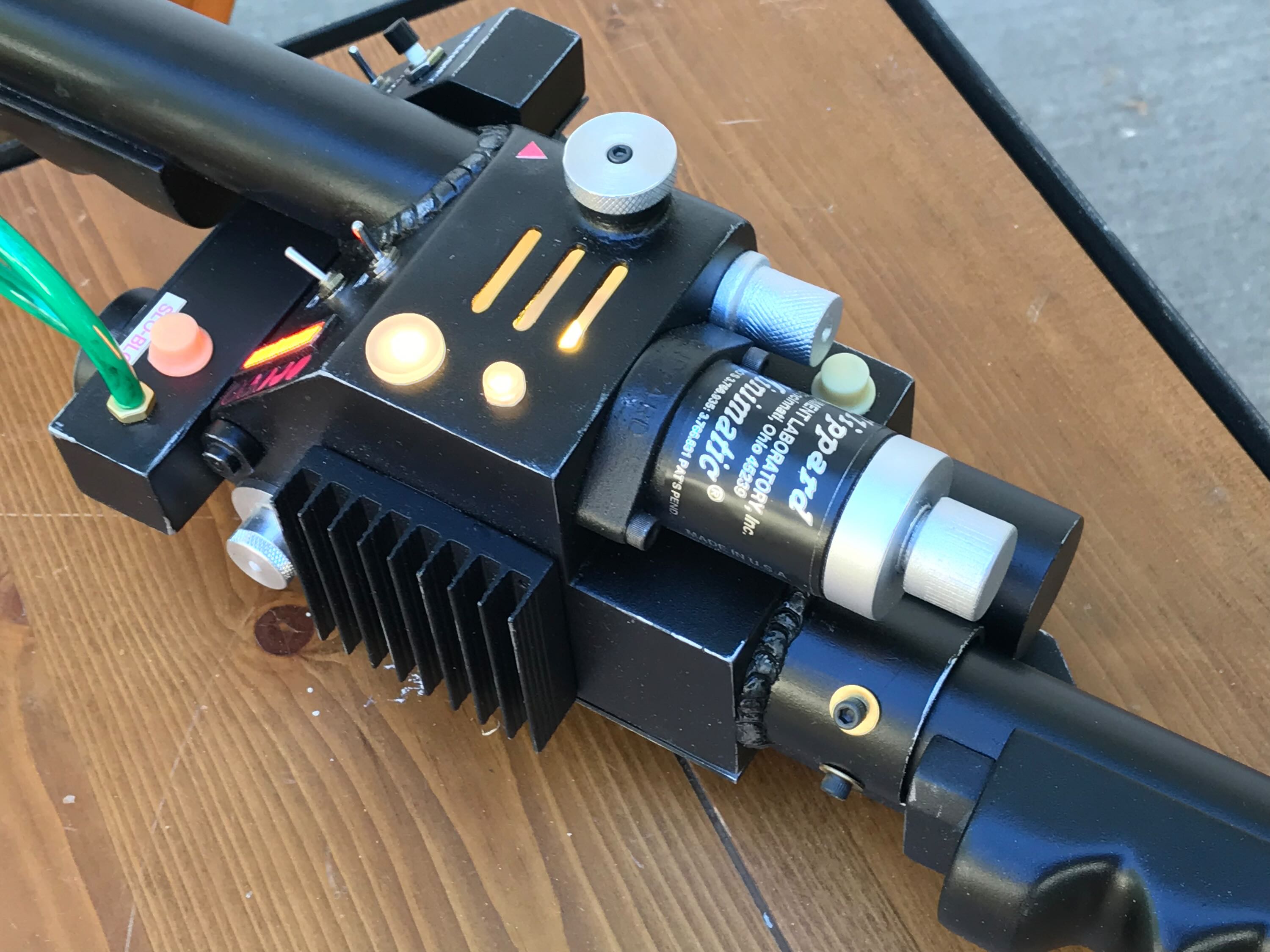
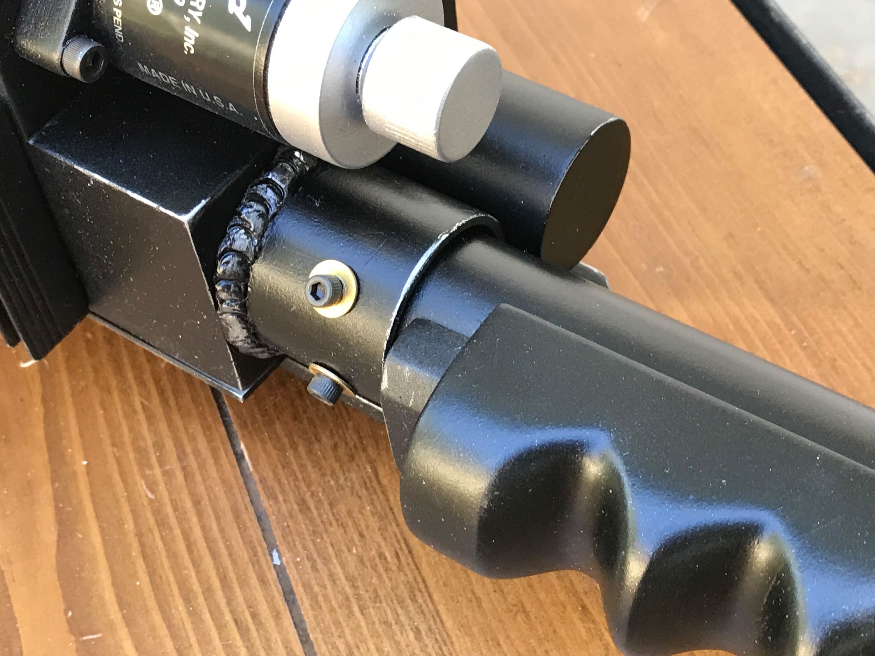
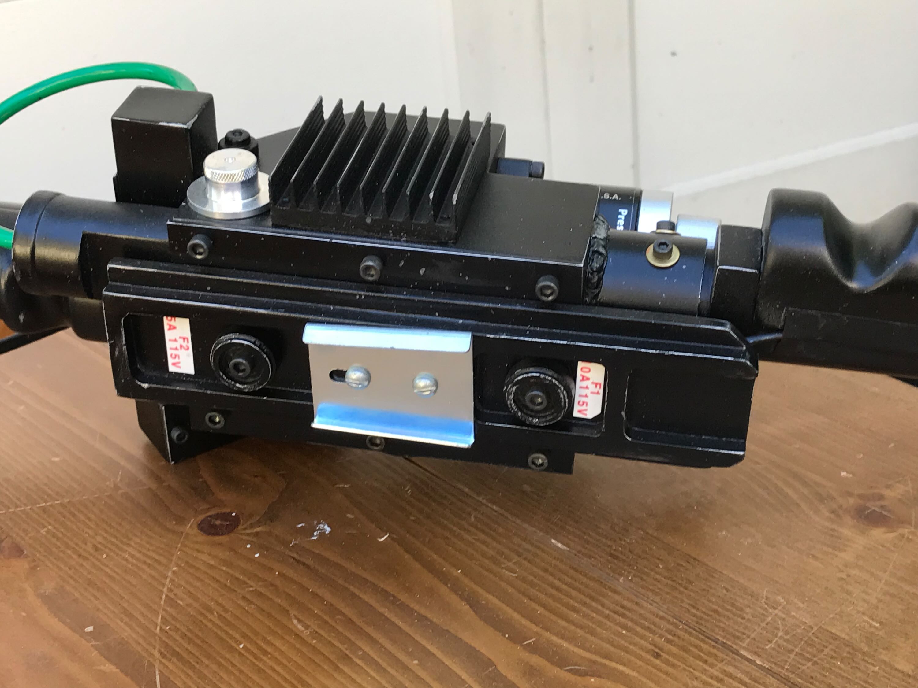
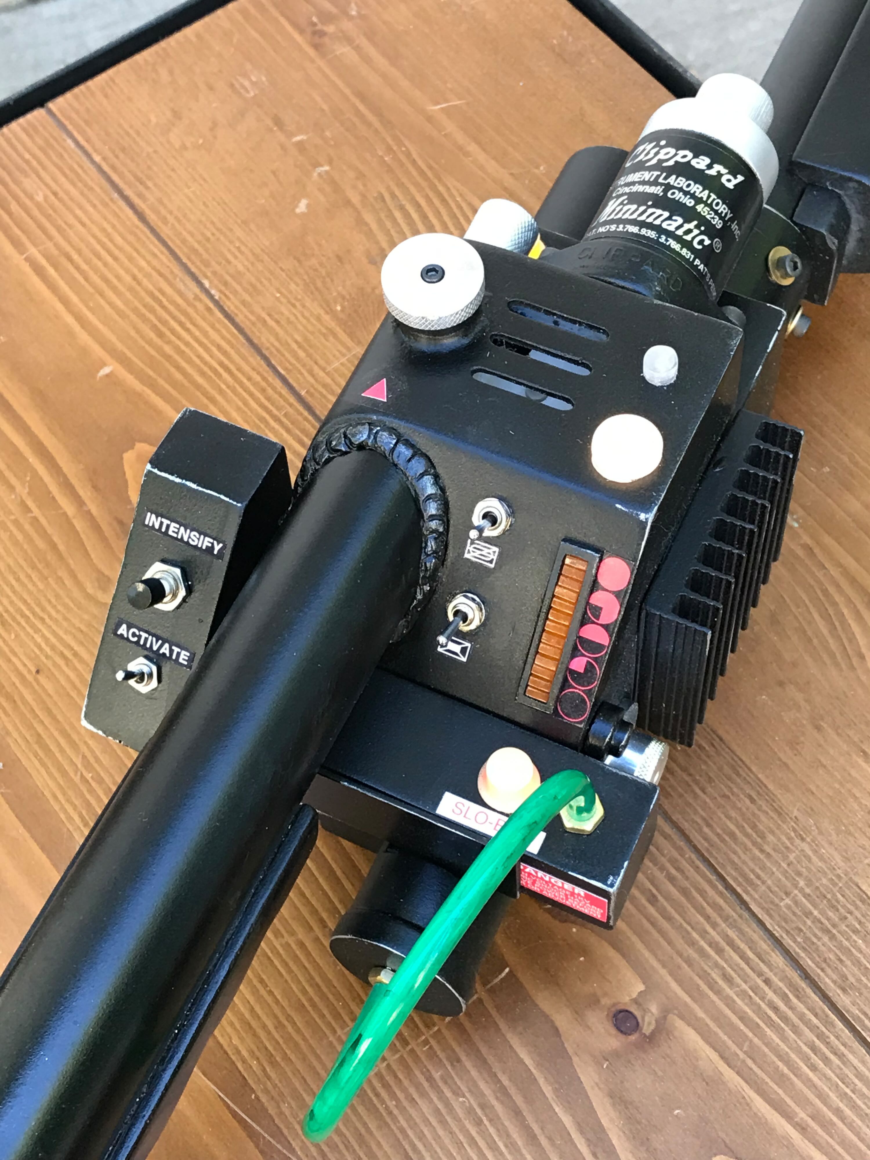
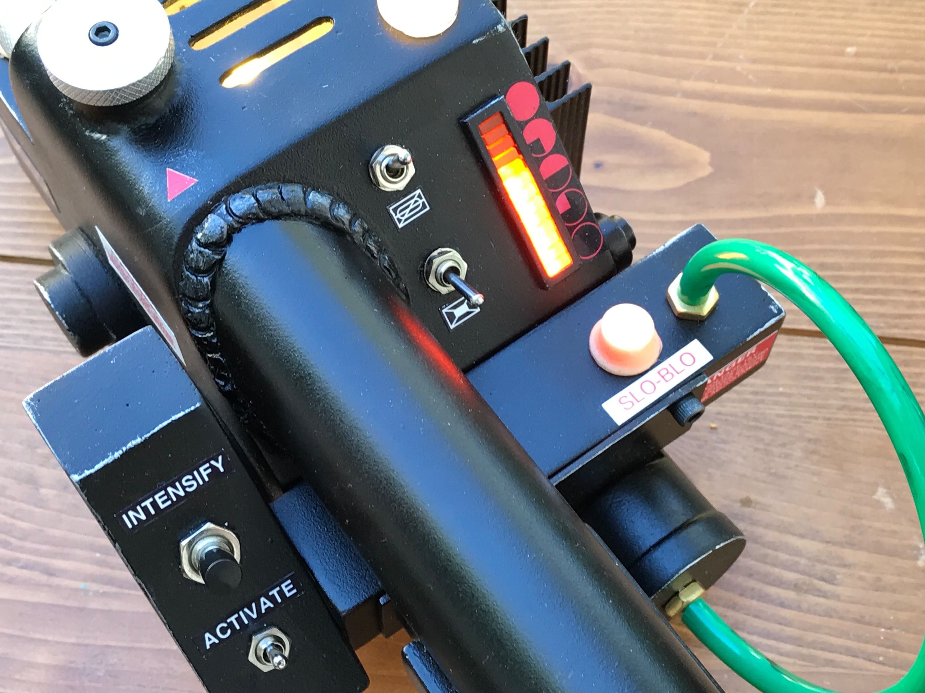
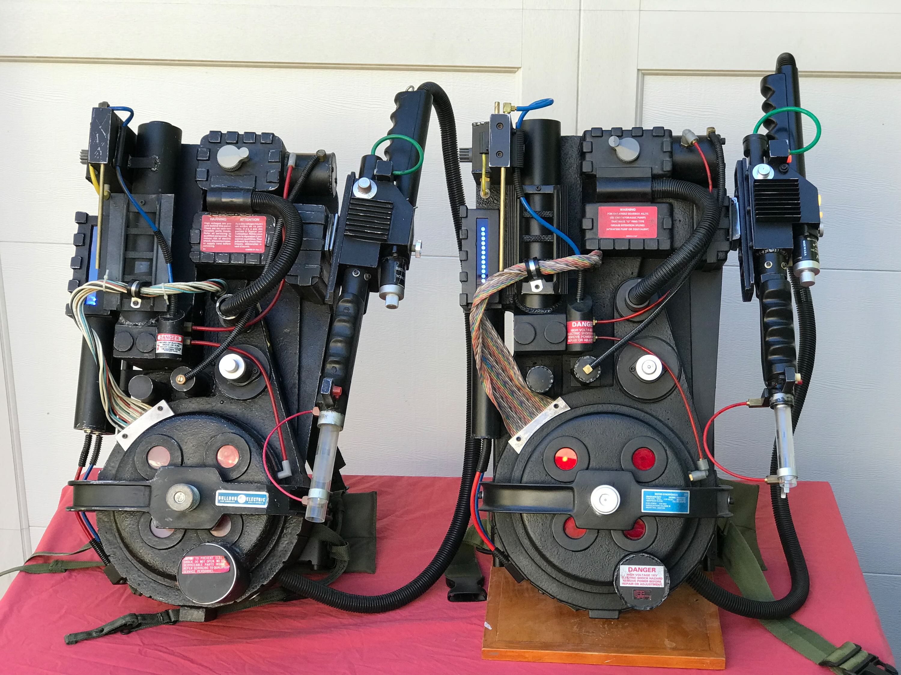
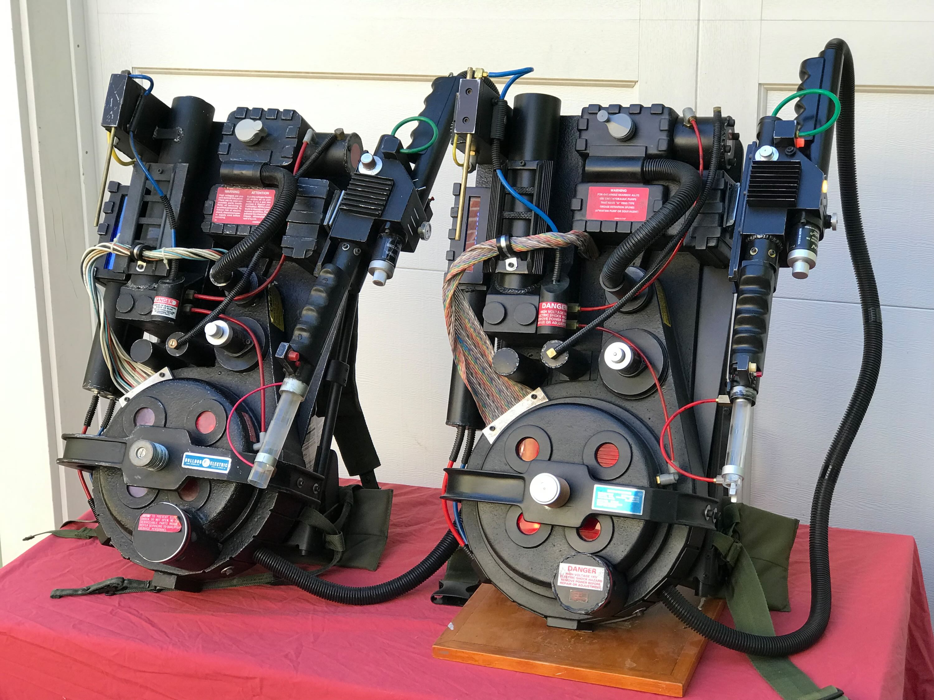
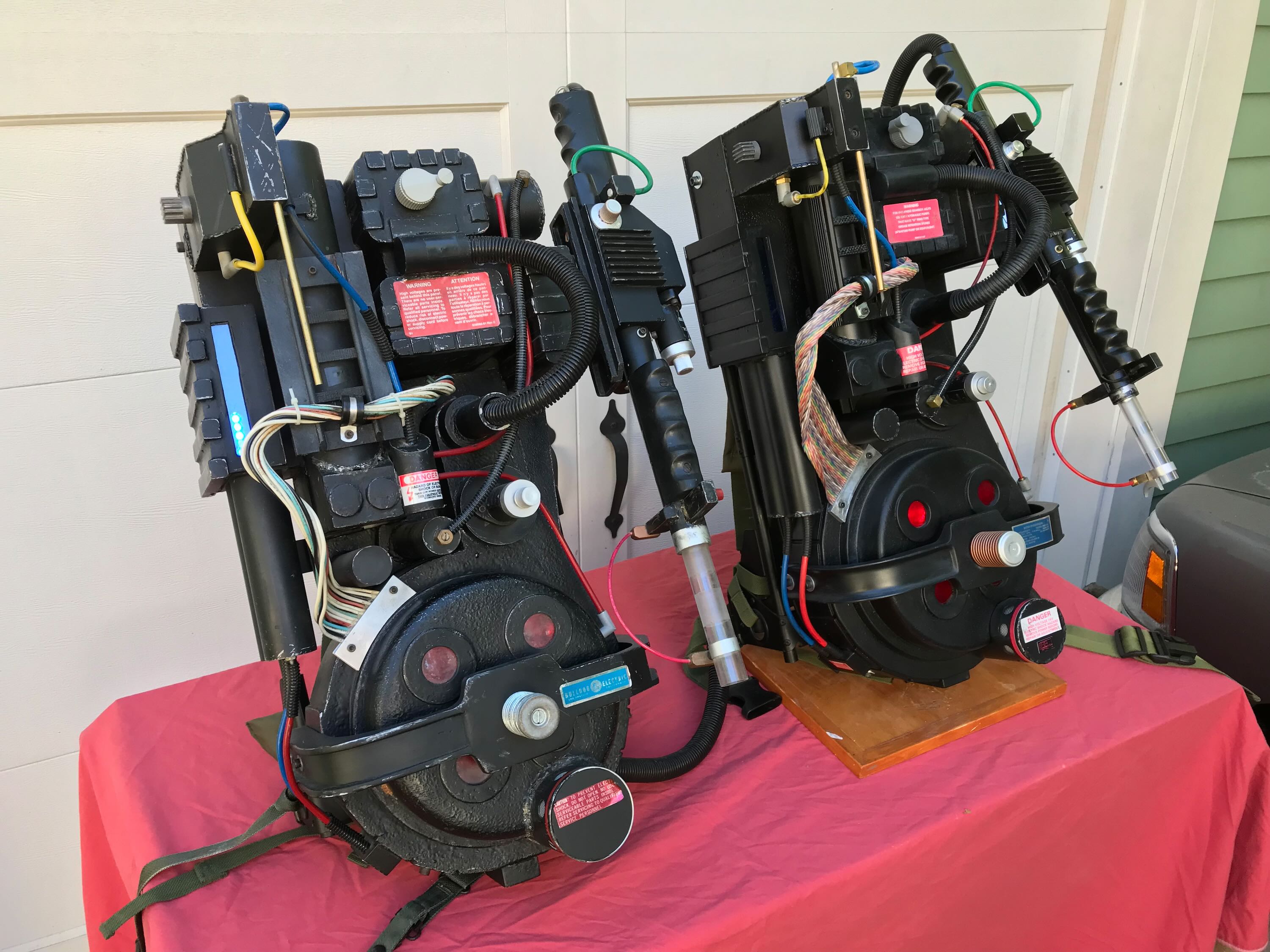
7/17/22 - The kit is missing the wider piece of pipe attached to the front of the thrower box. Looking through my boxes of junk I came across an old ABS tailpipe from one of our sinks. The diameter wasn’t perfect, but it was close enough.
With the handle parts worked out I epoxied it to the main box. I carefully measured the various heights to support the tip to ensure the handle would be perfectly perpendicular to the thrower box.
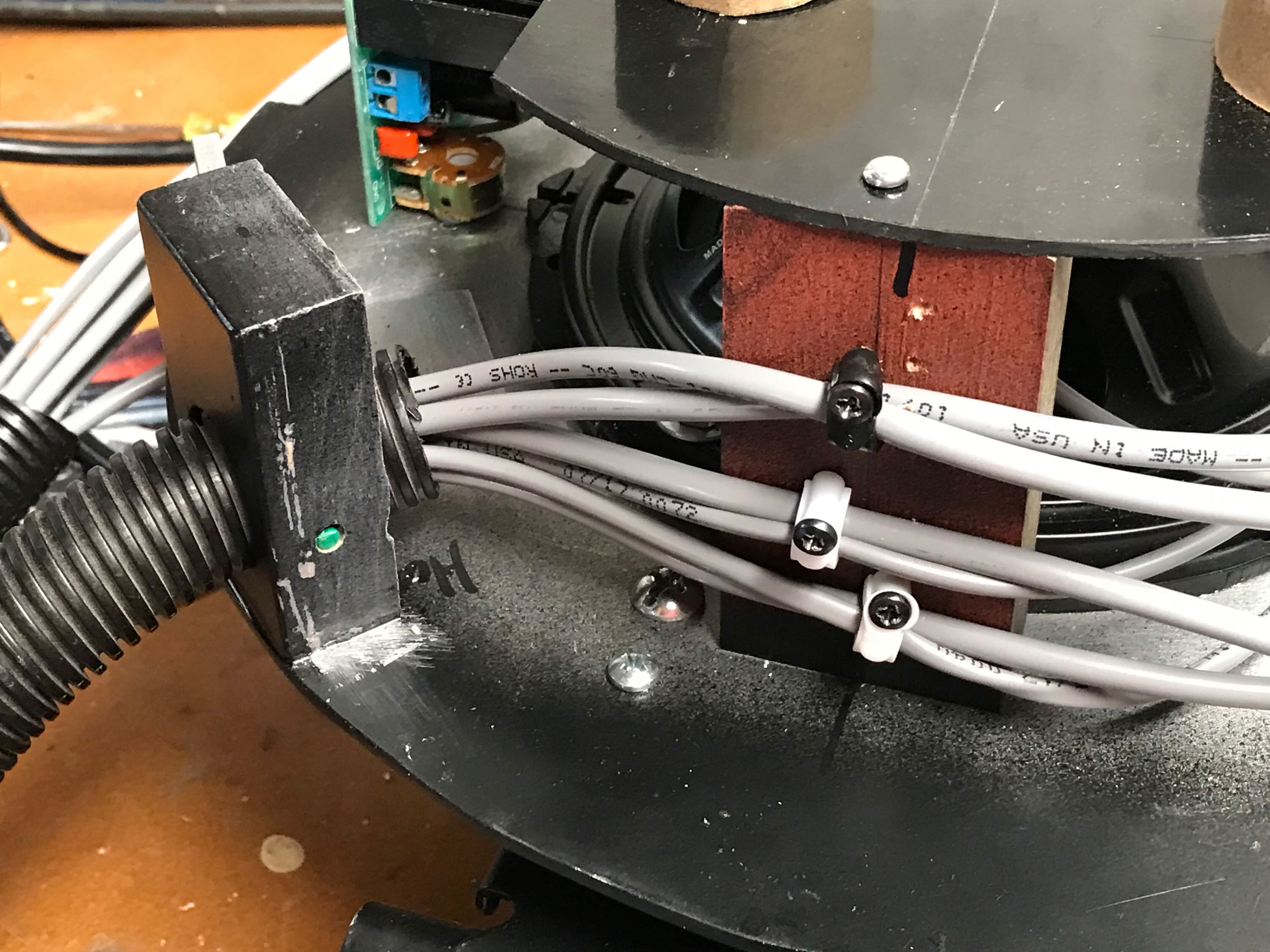
I drilled a hole through the side of the wooden hose opening block (and the hose). I could then push a steel rod through those holes to secure the hose in the block.
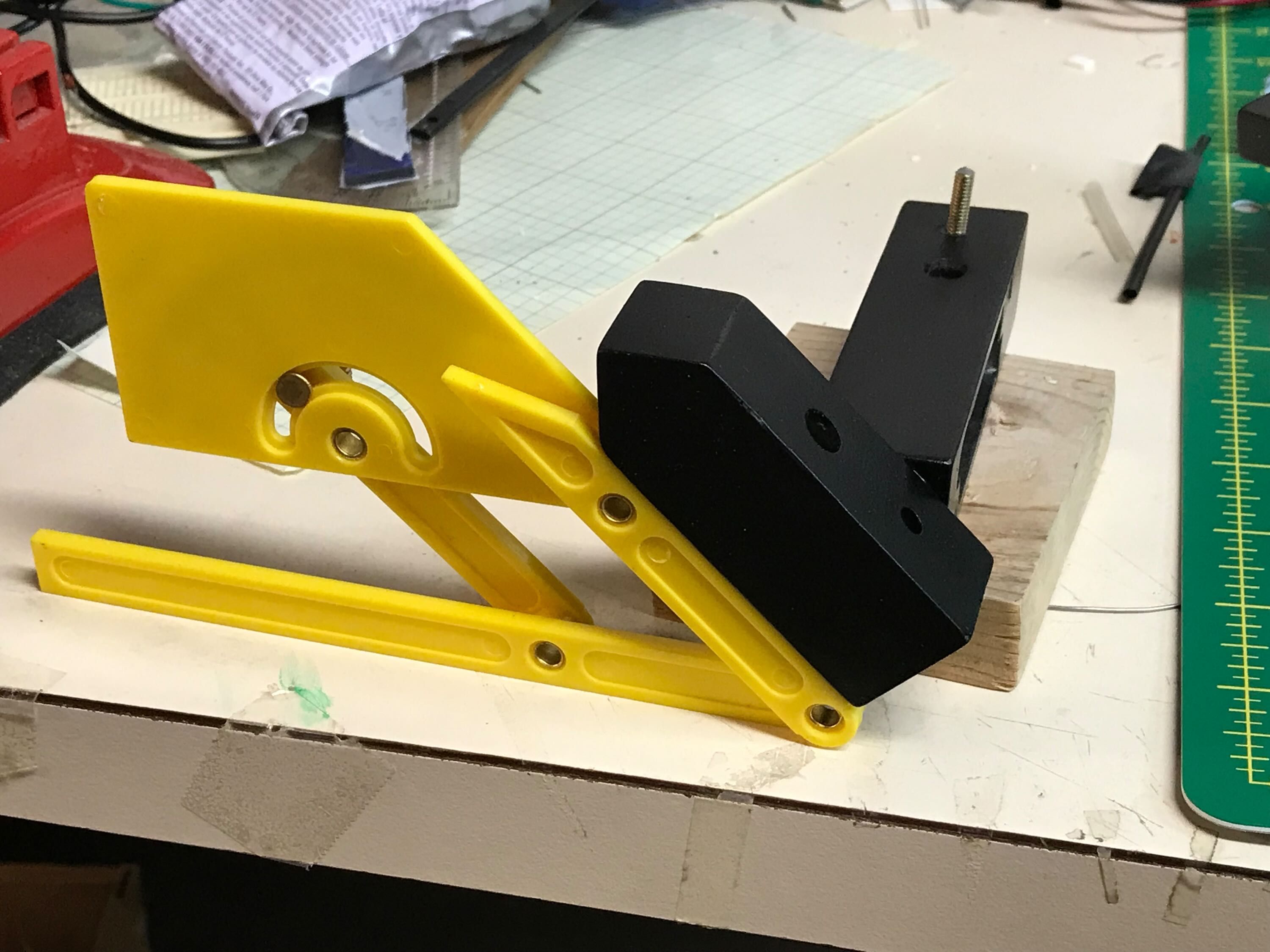
I used a little angle finder tool to help align the trigger box with the perpendicular part while gluing them with epoxy (and then bolting it). I’d tapped in 6-32 threaded rod into the perpendicular part so I could attach the green tube.
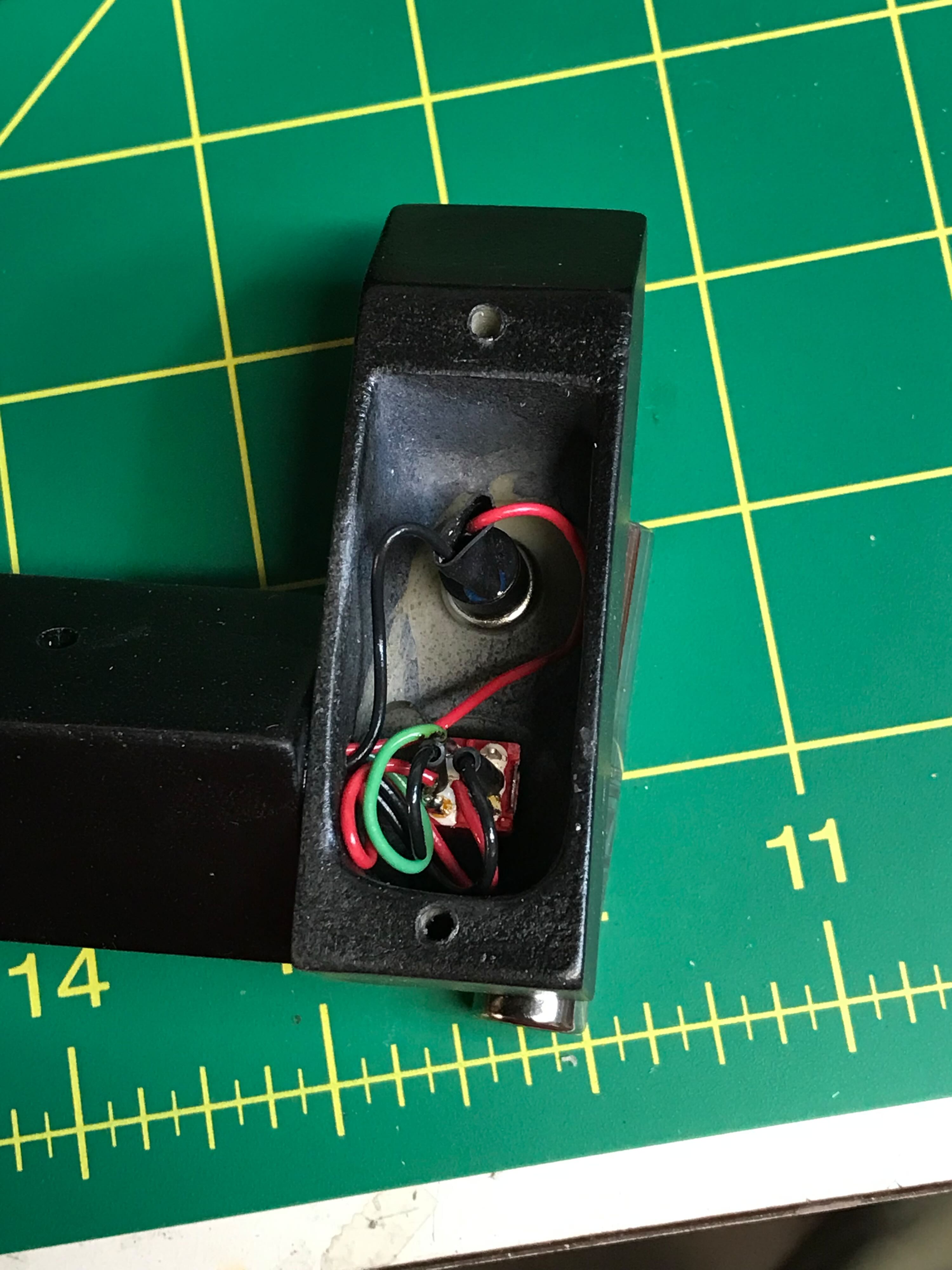
I installed the switches into the trigger box. Throughout this build I used a blue thread lock on all bolt/nut connections (and in the tapped resin parts).
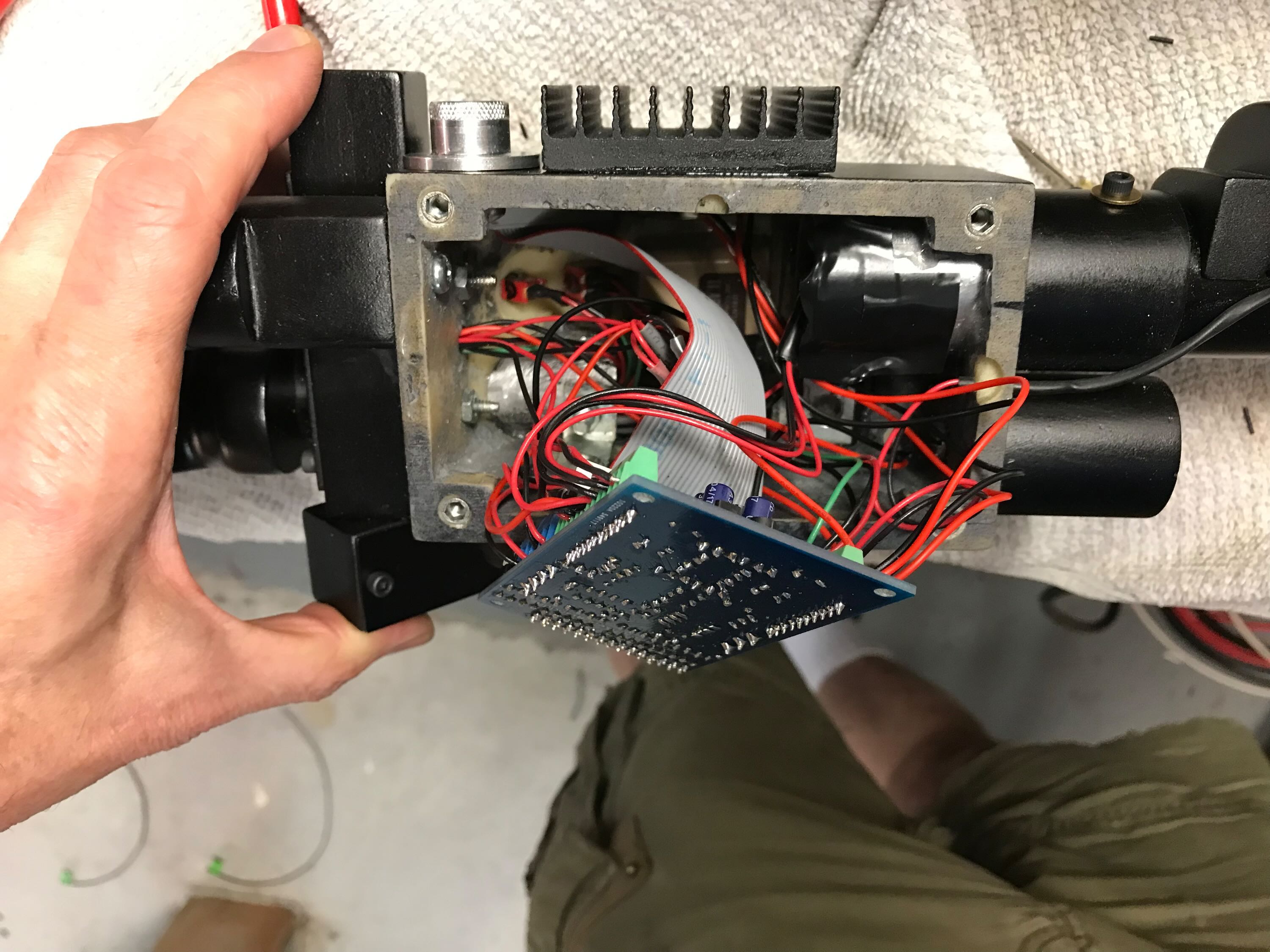
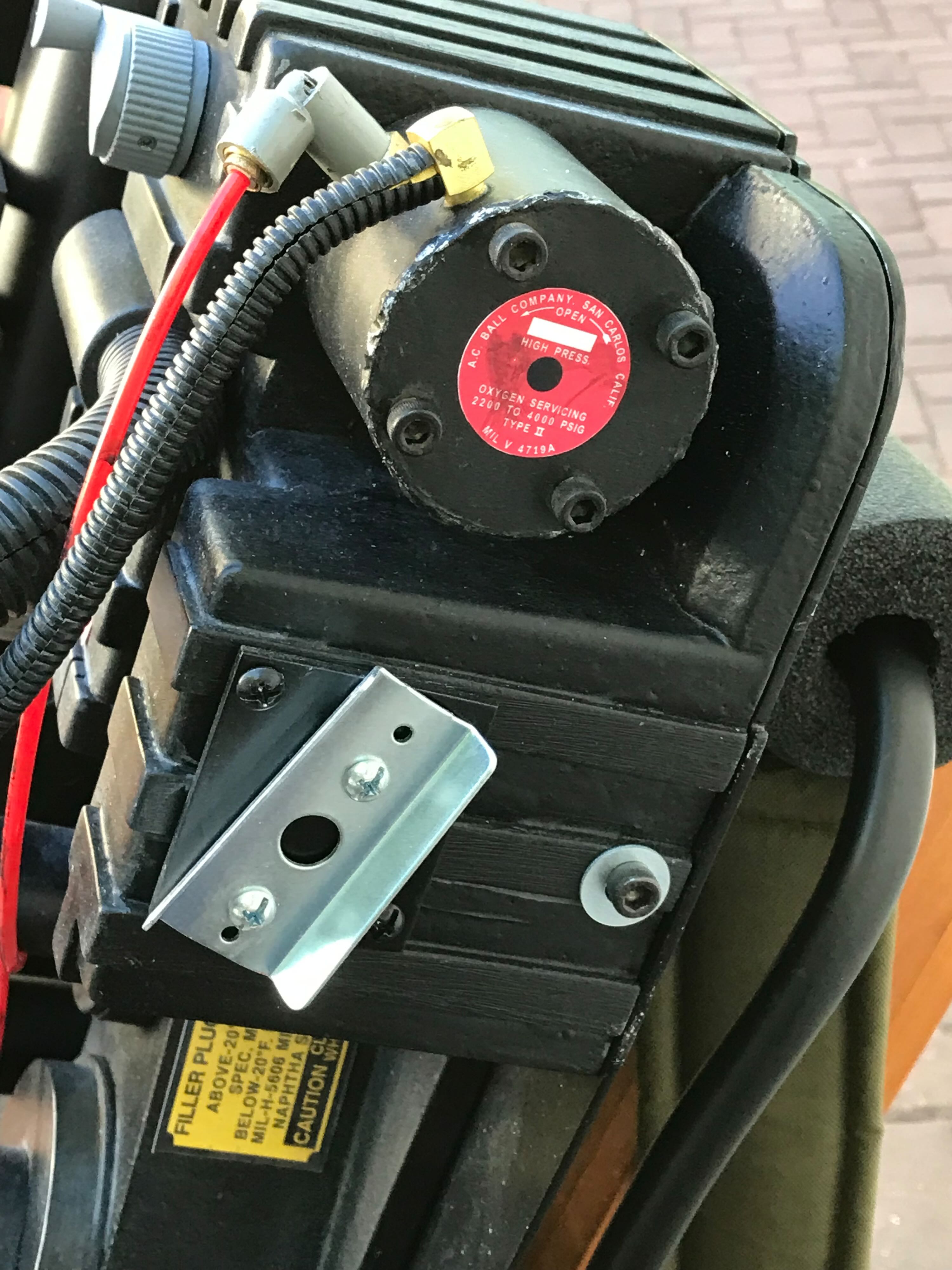
I bolted the trigger box assembly to the main box, running the wires through holes I’d drilled. I barely gave myself big enough holes to get those wires through. I’d also augmented the metal handle tubes with modified corner braces, bolting those to the tubes after epoxying them to the resin box
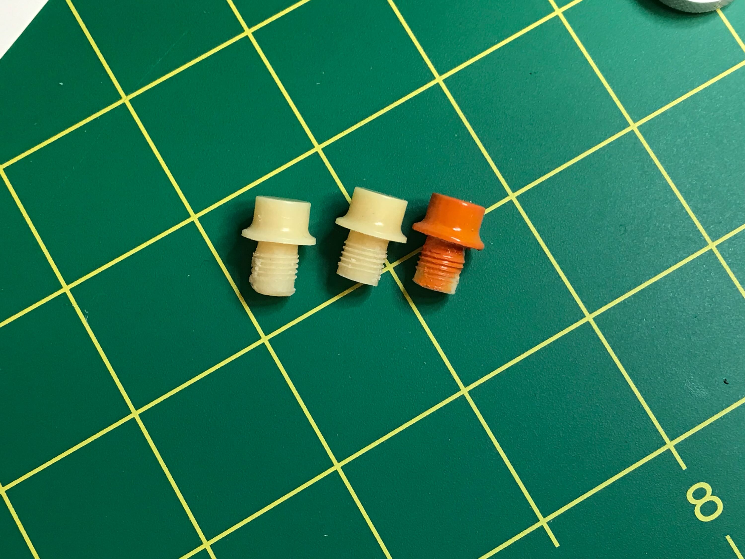
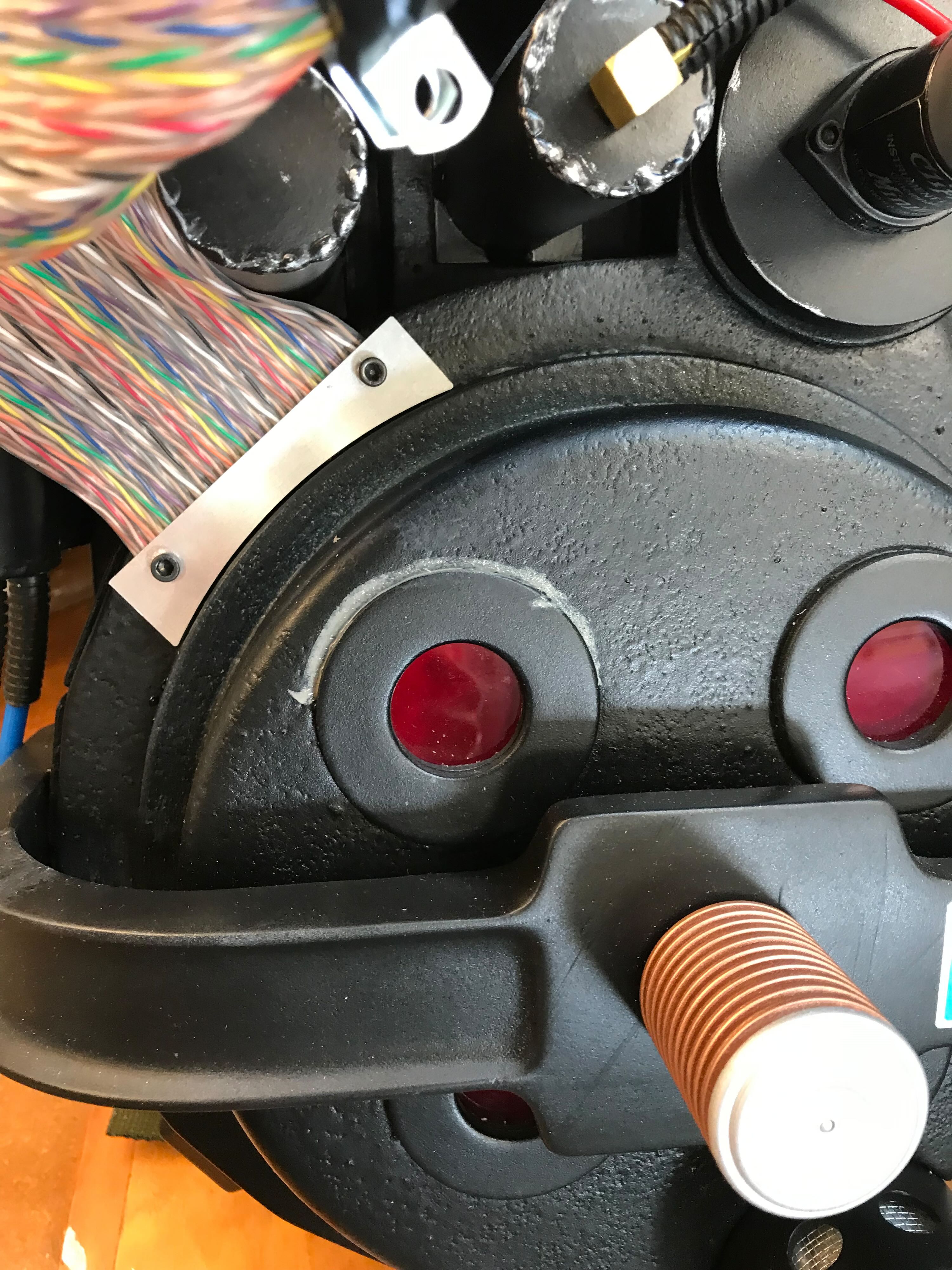
The kit came with resin versions of the three hat lights. I didn’t want to make Wes invest in proper, transparent light covers, so I endeavored to make these resin versions work. By drilling down into the resin I was able to fit LEDs up into them, and the thinner resin allowed a decent amount of light through. I thought the orange painted onto one of the hats would block the light too much, so I removed that paint.
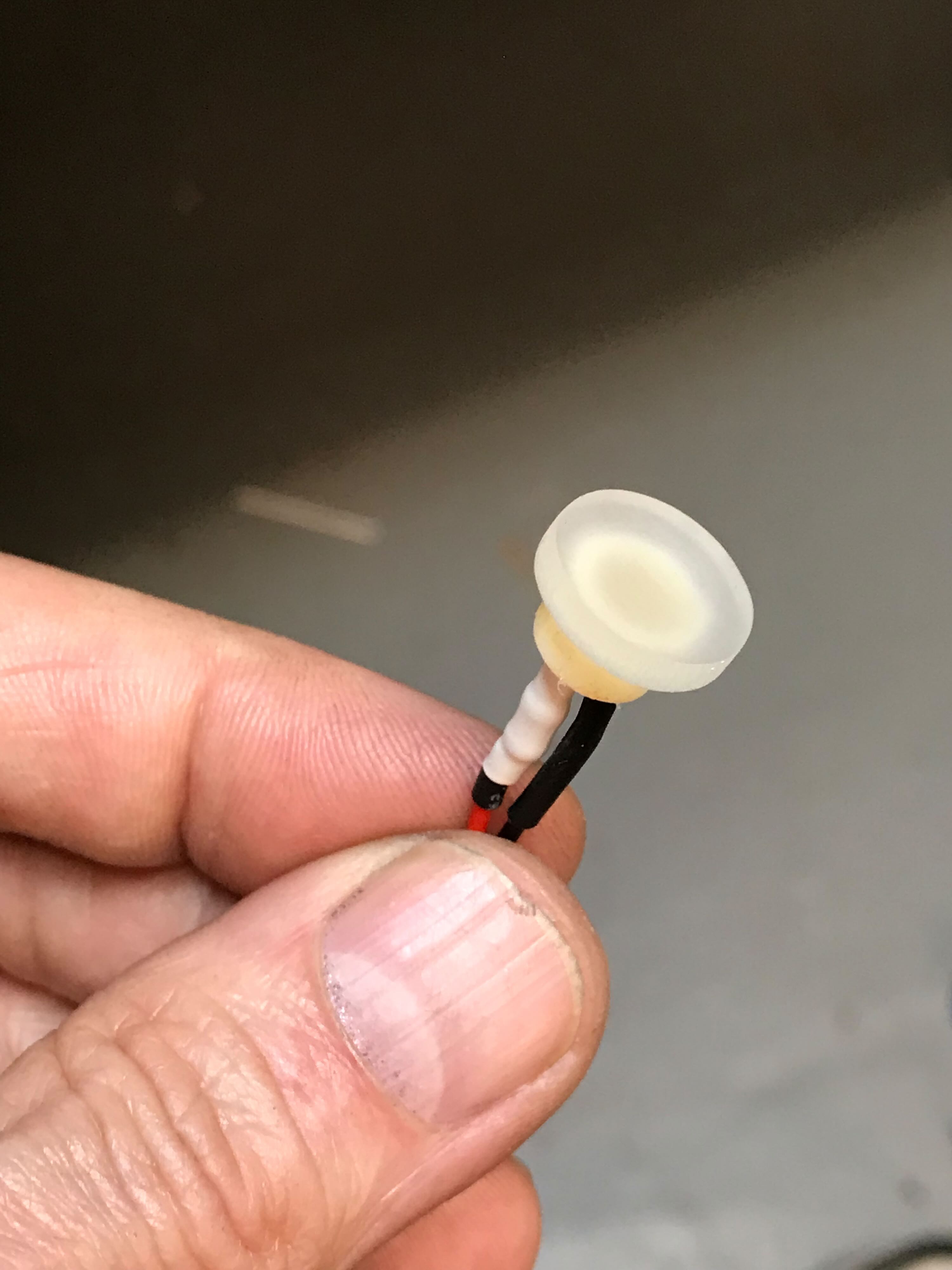
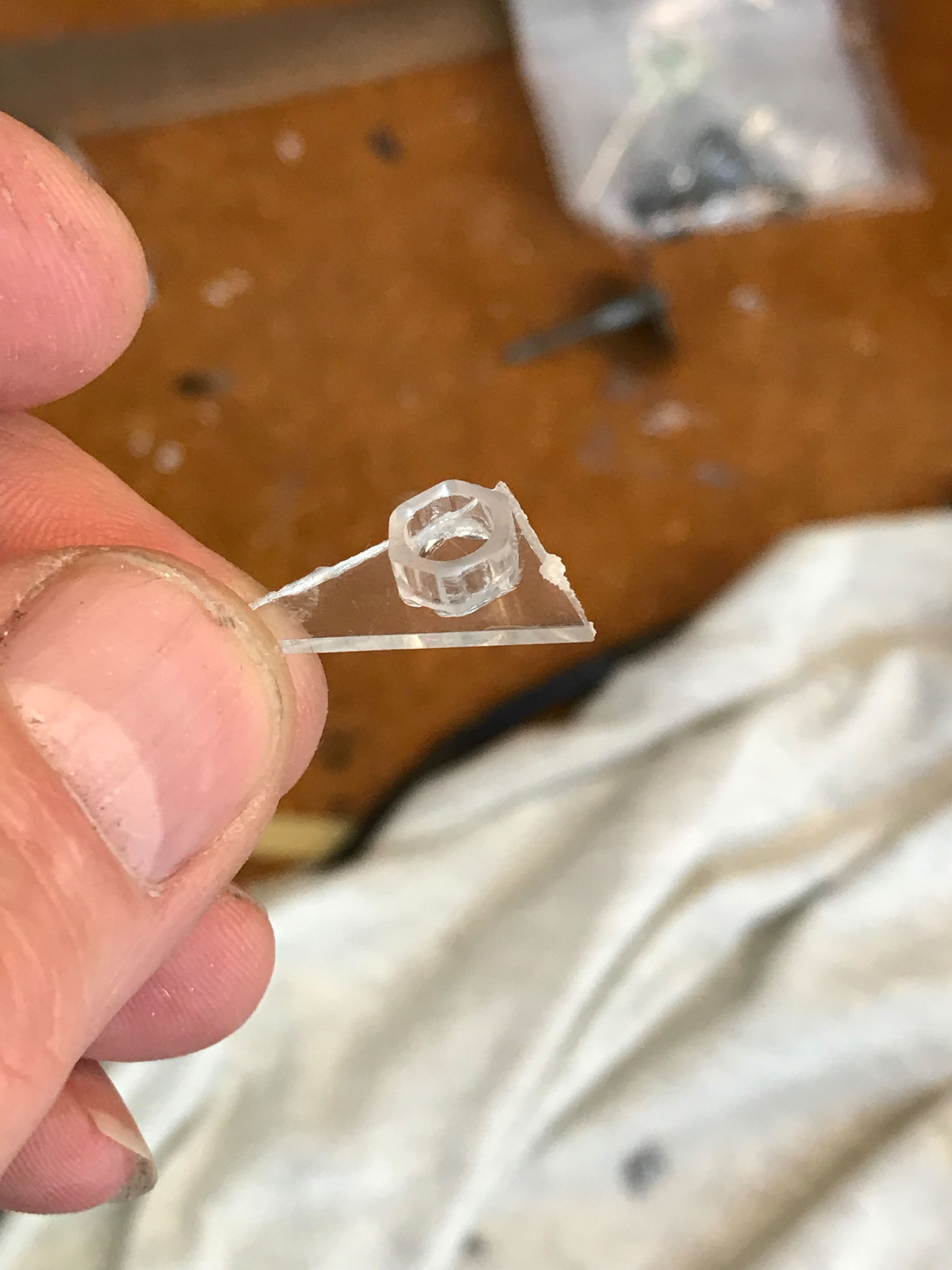
The kit is missing the two lights next to the vent opening, so I had to fabricate approximations. For the big one I used double-sided tape to stick a metal washer onto a piece of translucent acrylic I got free from TAP Plastics. I could then use my Dremel cutting and sanding tools to create a round part the correct size. I glued that to a part I cut off of a coax cable wall jack, and I’d hot glue the LED into that. Close enough.
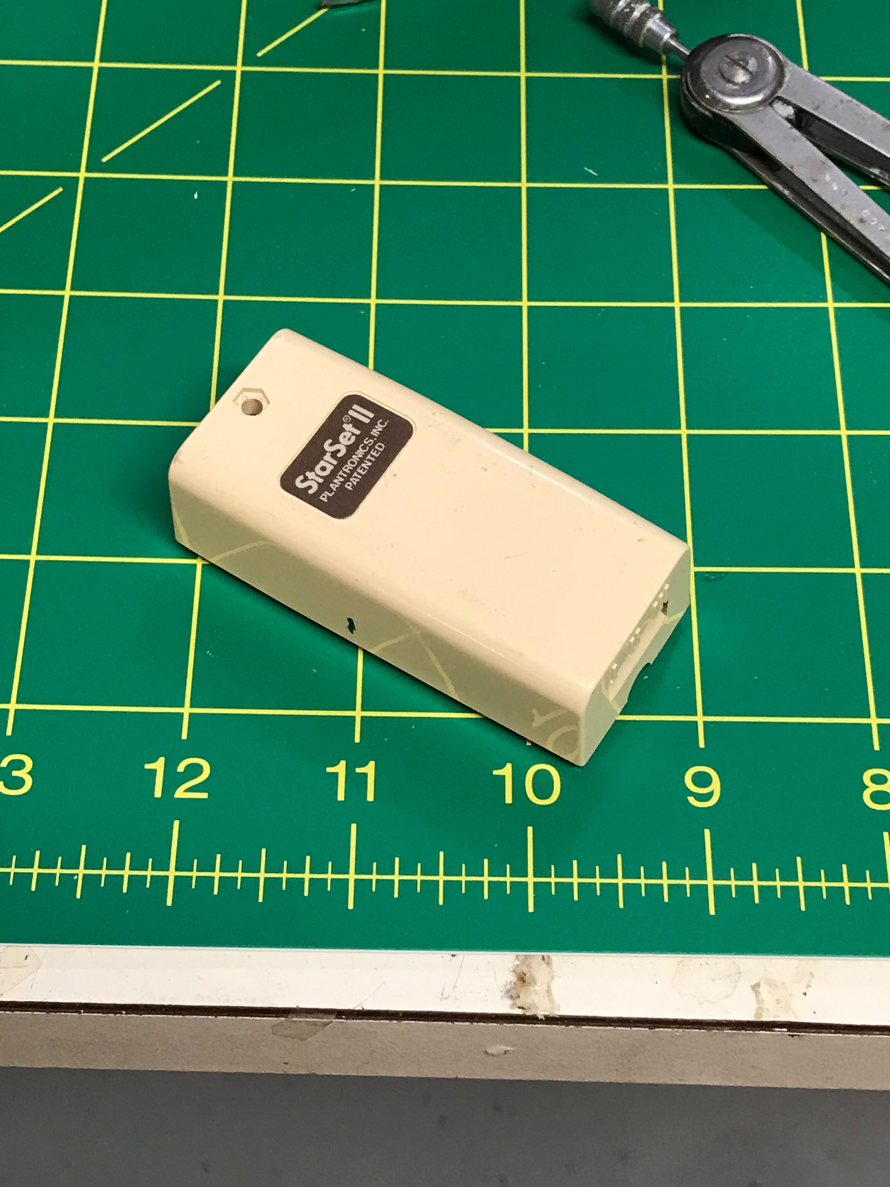
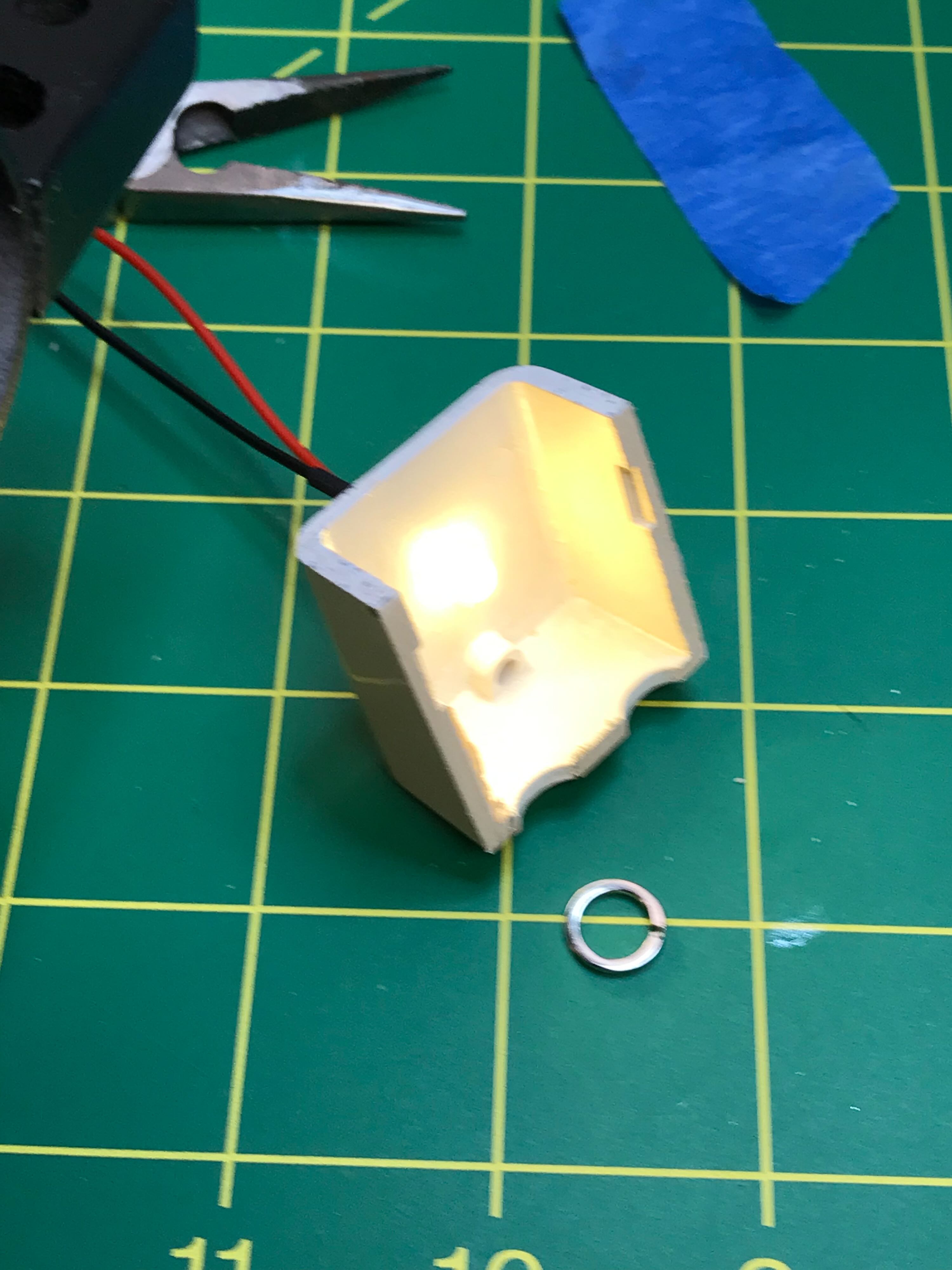
7/18/22 - The LED for the vent light that came with the electronics kit was a single, diffused 5mm LED. I wanted to mount that in a white box to help bounce around its light. Again going through my boxes of junk I found an old headset I’d used back when I worked at KGUN-TV in Tucson in the early 90s. I cut open the cover, painted the inside white, and glued in the LED.
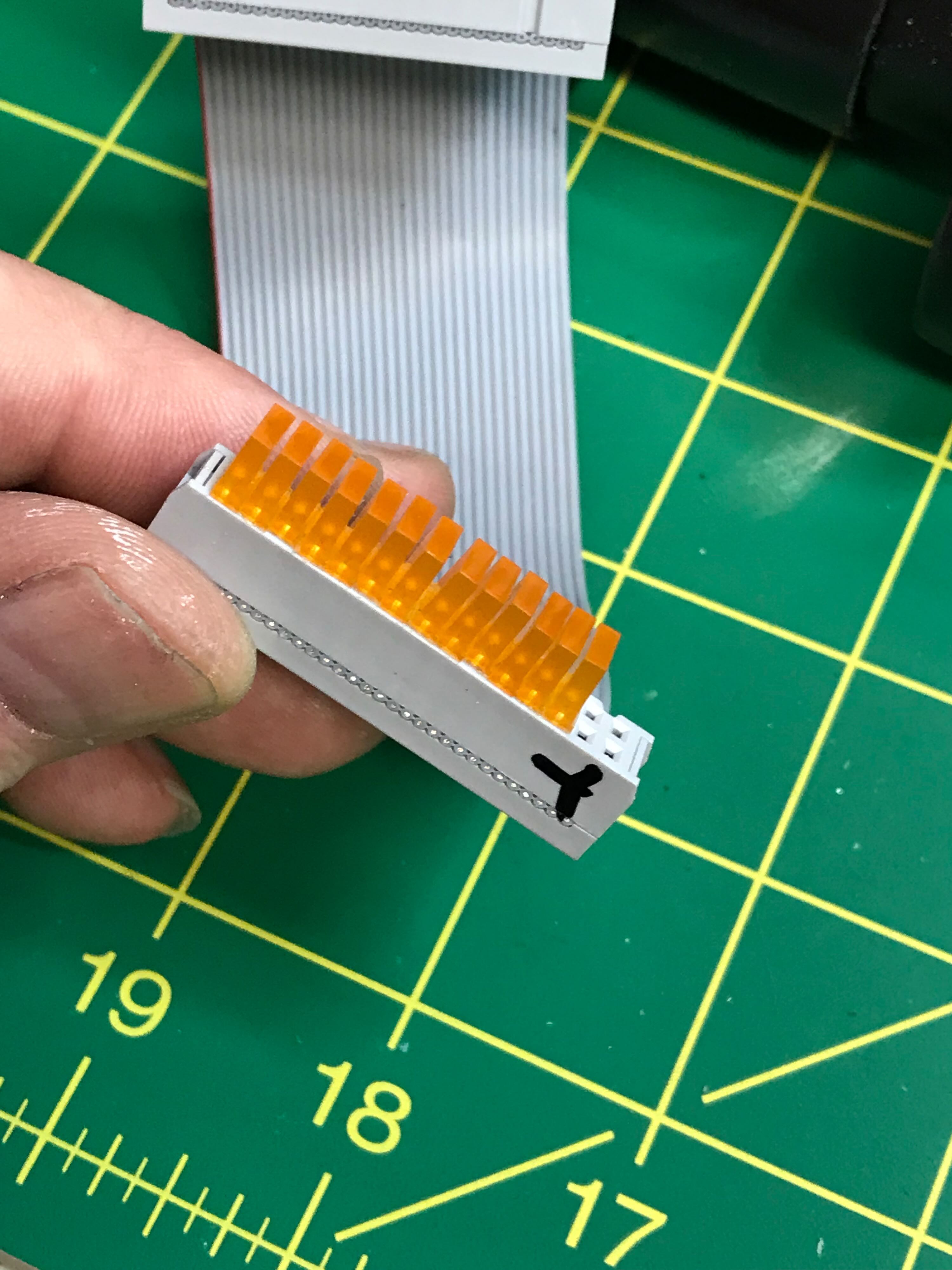
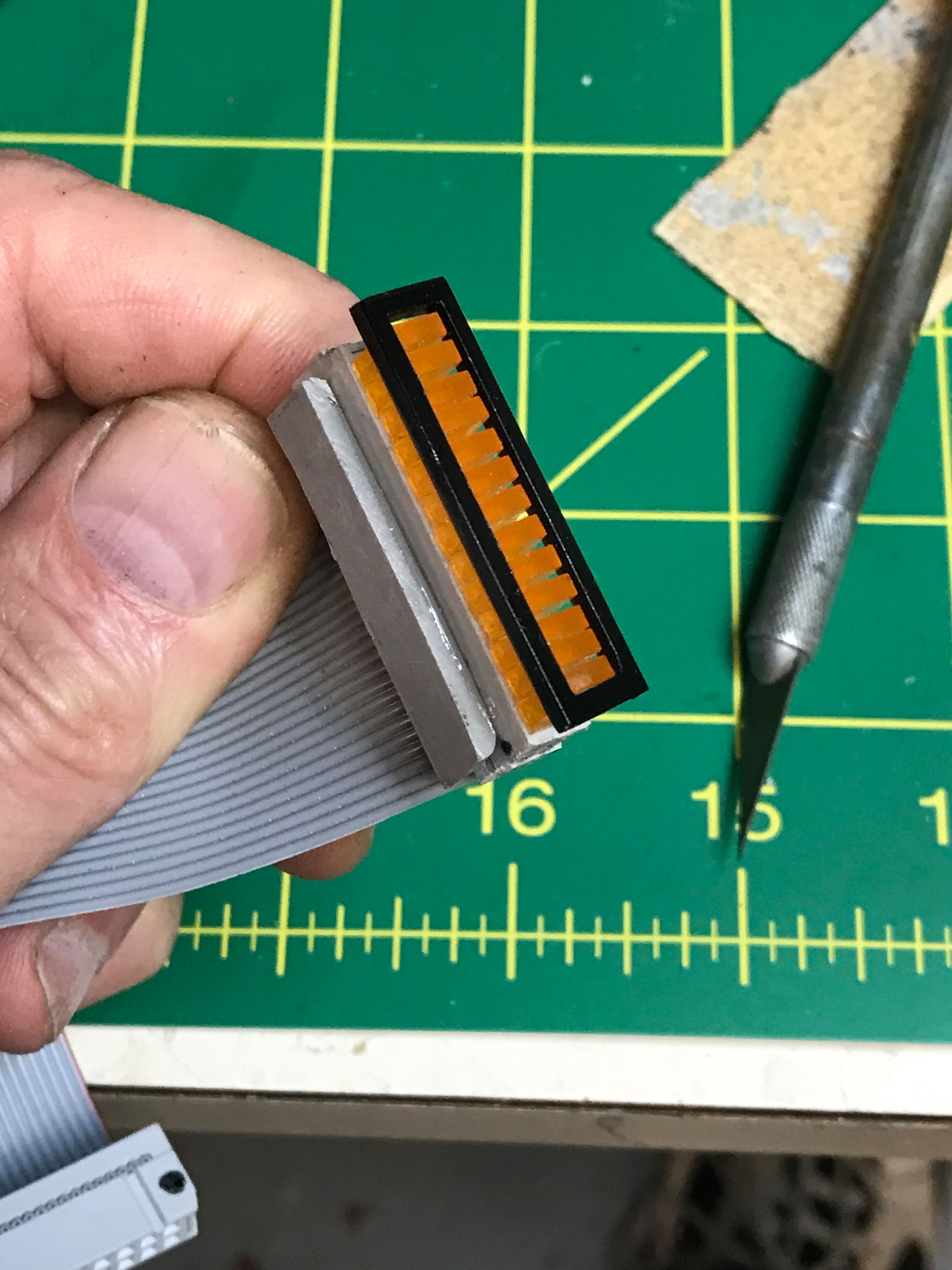
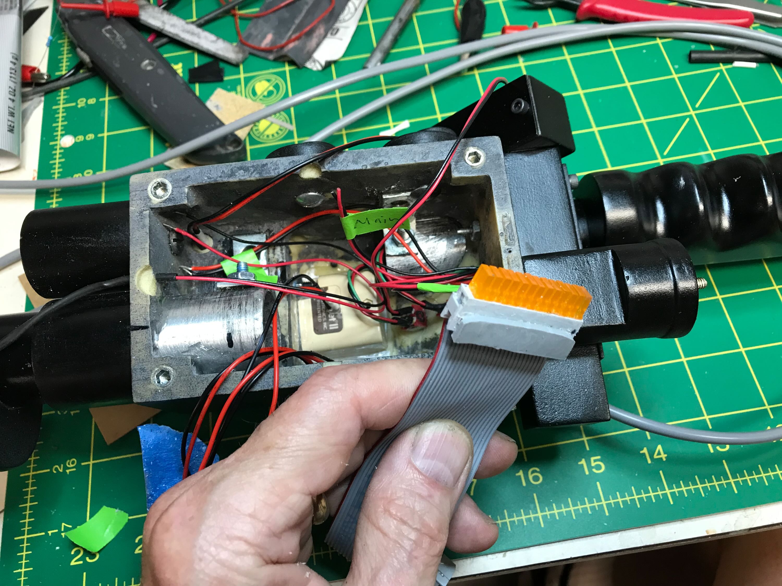
The bar graph LEDs with the kit were a bit of a kludge. The developer simply stuck the rectangular LEDs into a ribbon cable connector. The first problem was that, with all 15 slots filled with LEDs, it was too long for the opening on the thrower. It was a simple matter to just pull out the top two LEDs. That didn’t affect the visual appearance. I would also have to chop off that end of the connector so it would fit into the box.
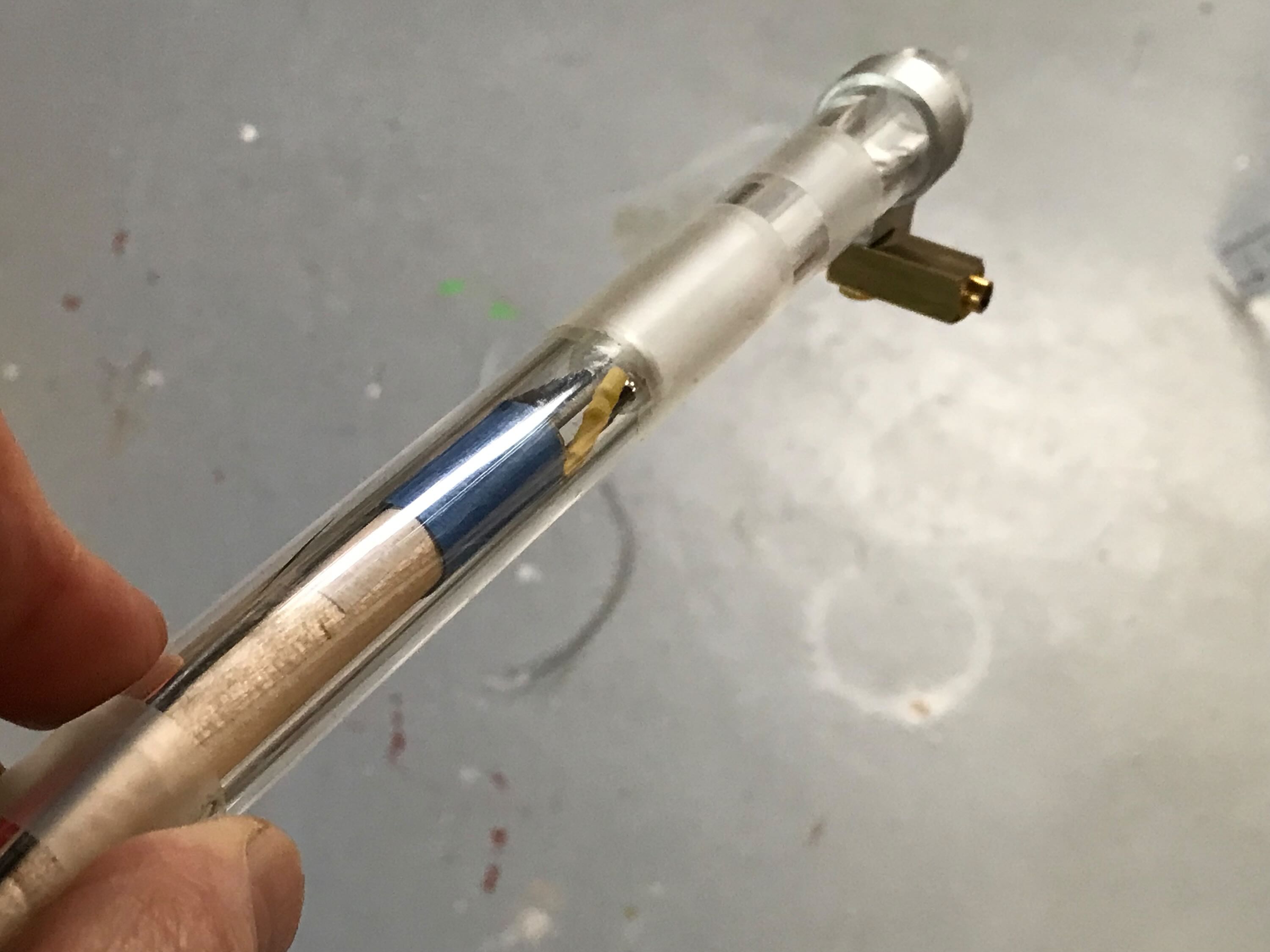
I had to fabricate the second, smaller light next to the vent. I cut off a chunk of a clear plastic BIC ballpoint pen, glued that to a piece of clear plastic, then sanded that down into a round-ish shape. I would then hot glue an LED up into the opening. Again, close enough. After working on this for 28 days I was getting impatient to finish the build.
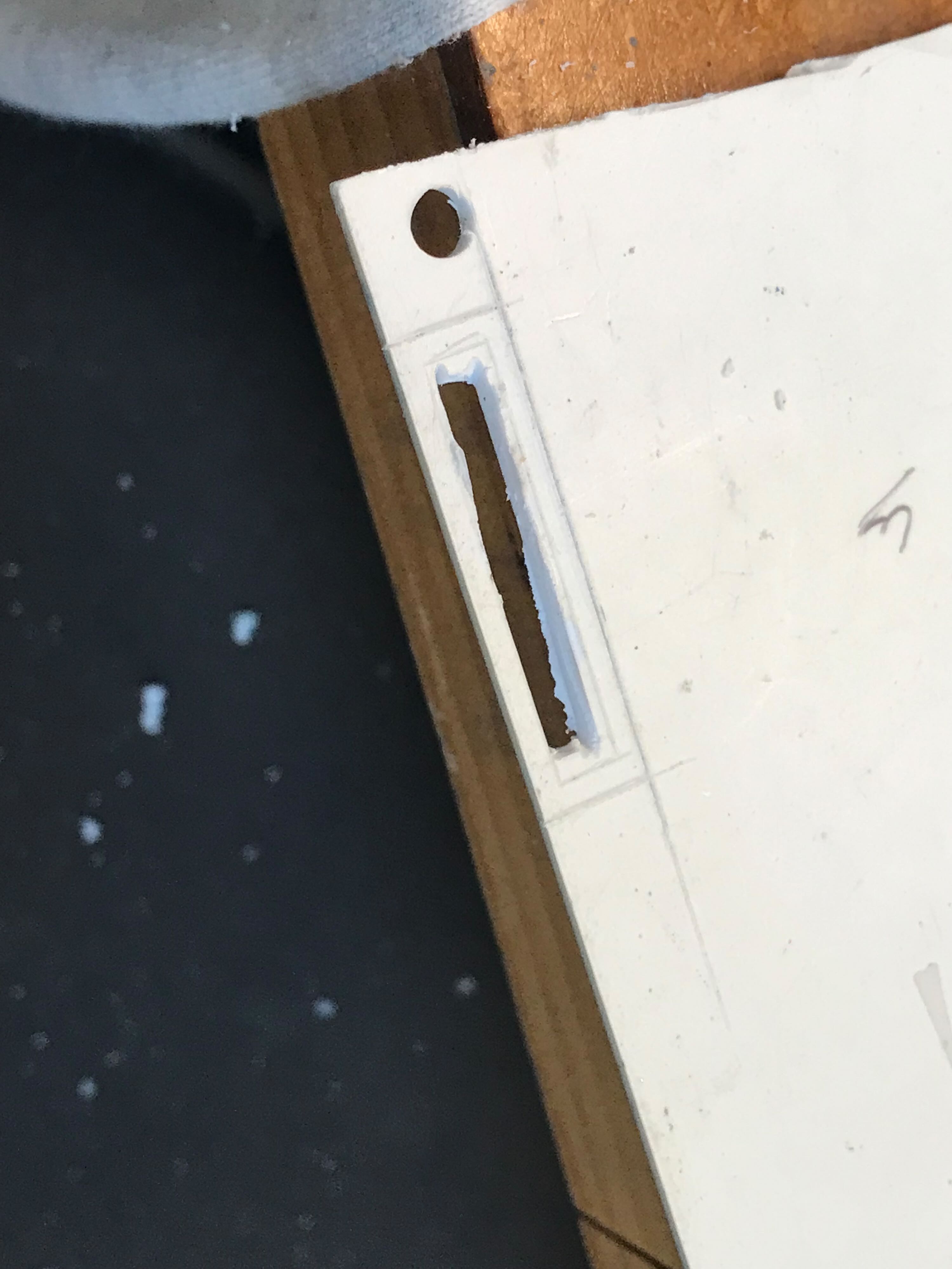
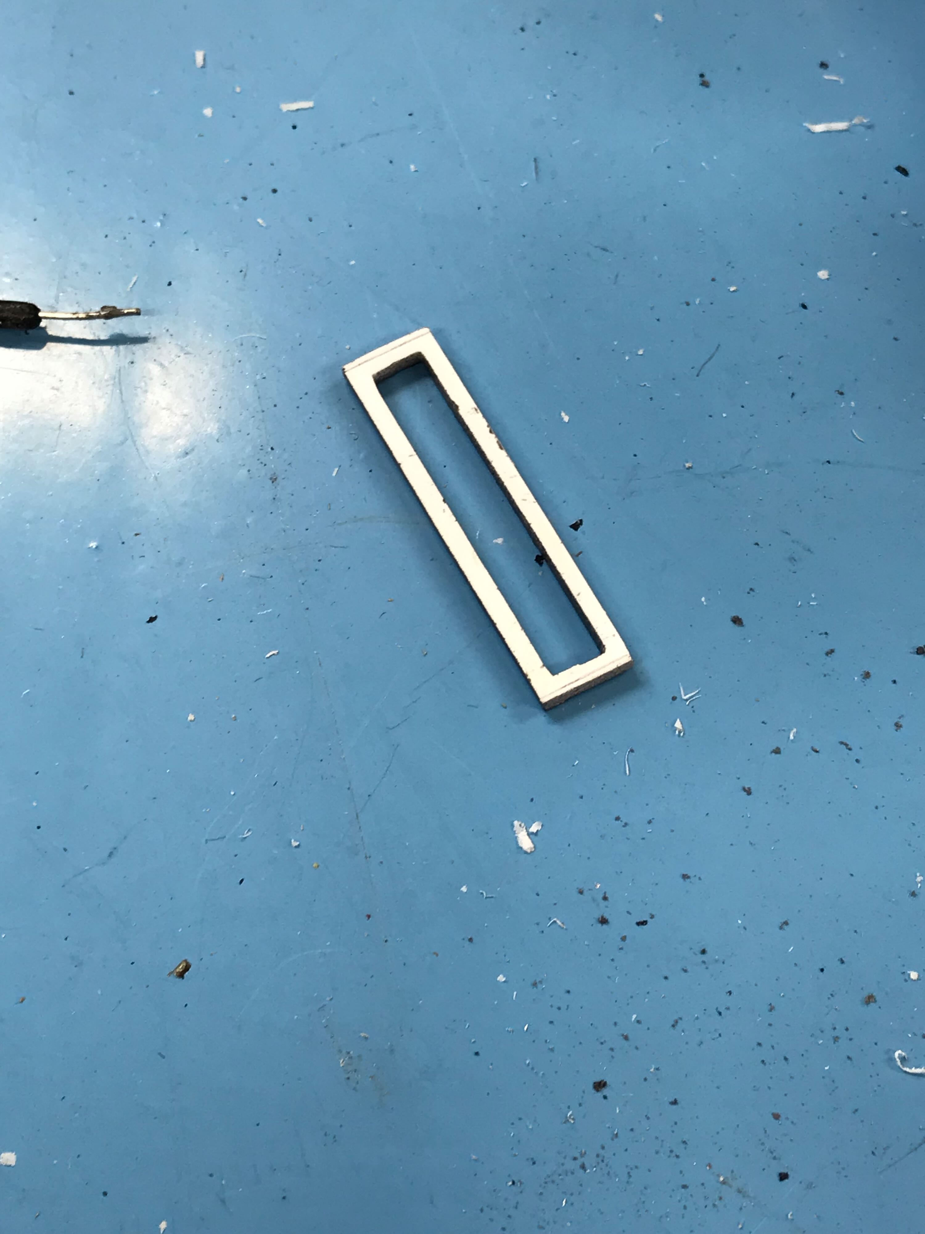
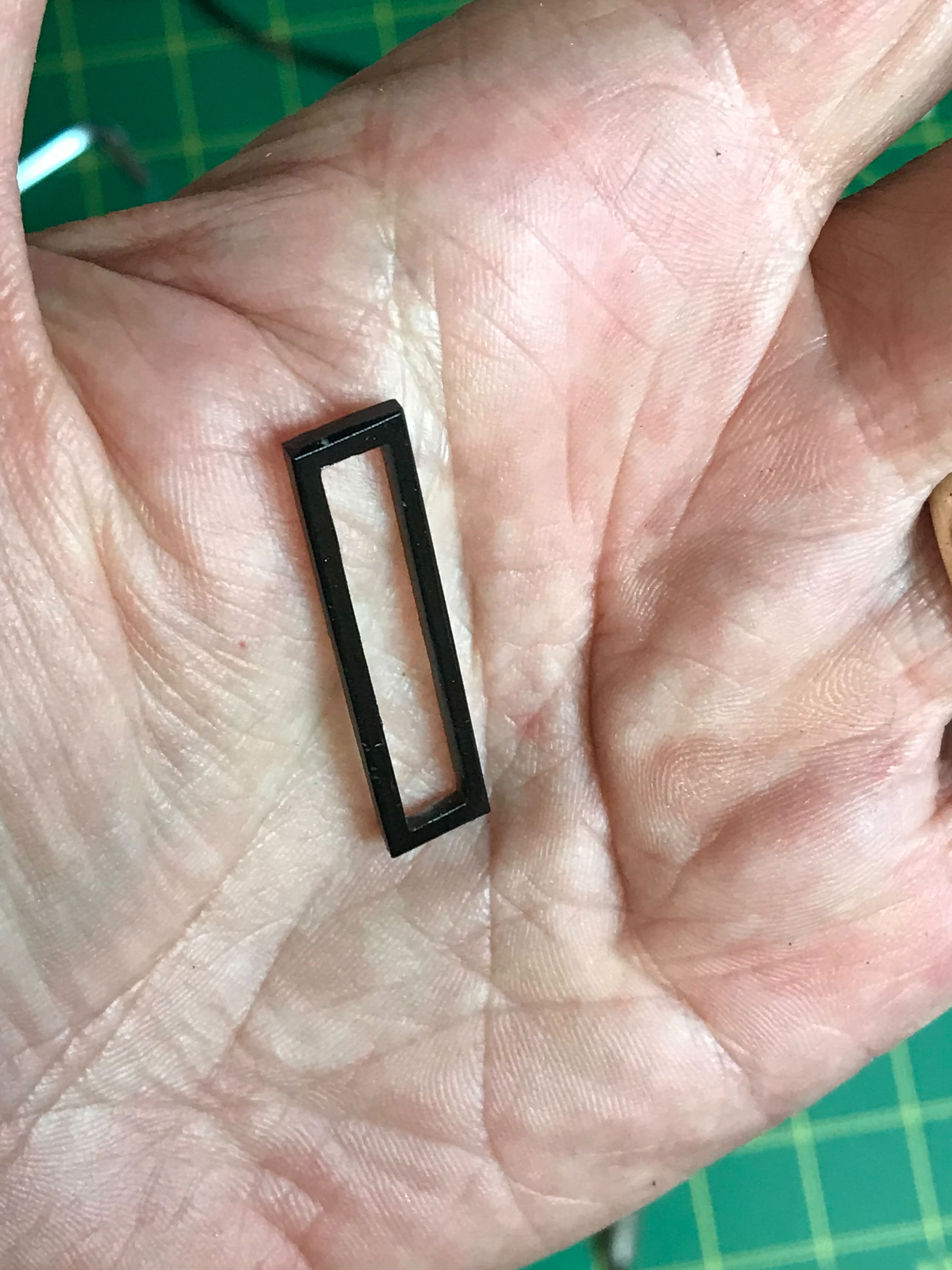
For no apparent reason the kit doesn’t have the bezel around the bar graph LEDs molded into the thrower box, so this was yet another piece I had to fabricate from scratch. I carefully cut it from a piece of sheet plastic.
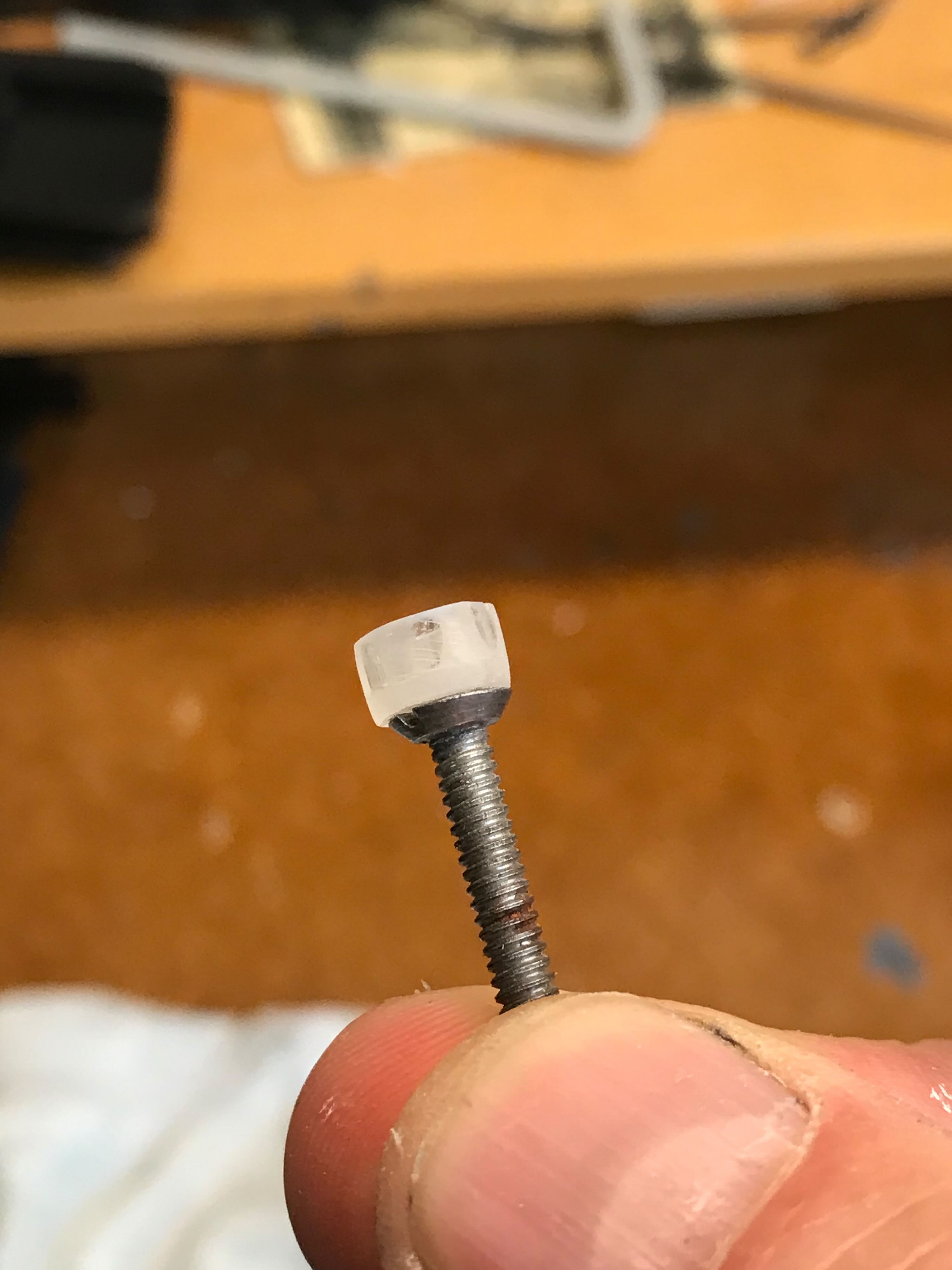
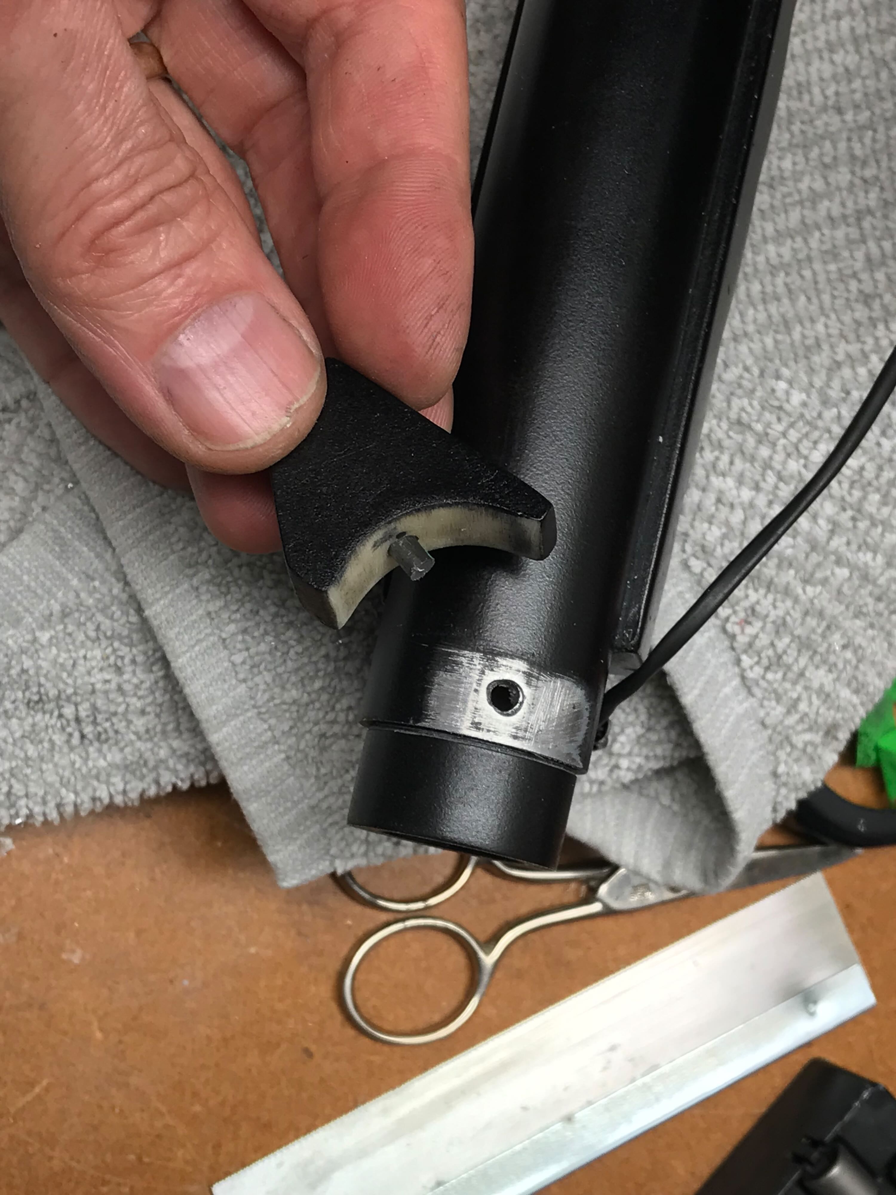
I didn’t want to rely on just epoxy to fasten most of the parts, so on parts like this thrower tip I added a short length of threaded rod to add mechanical strength to that connection.
7/19/22 - After some research (mainly cribbing off of Gohstarp’s build) I masked the acrylic thrower tube and sprayed multiple coats of Krylon Clear Matte to frost the appropriate sections of the tube.
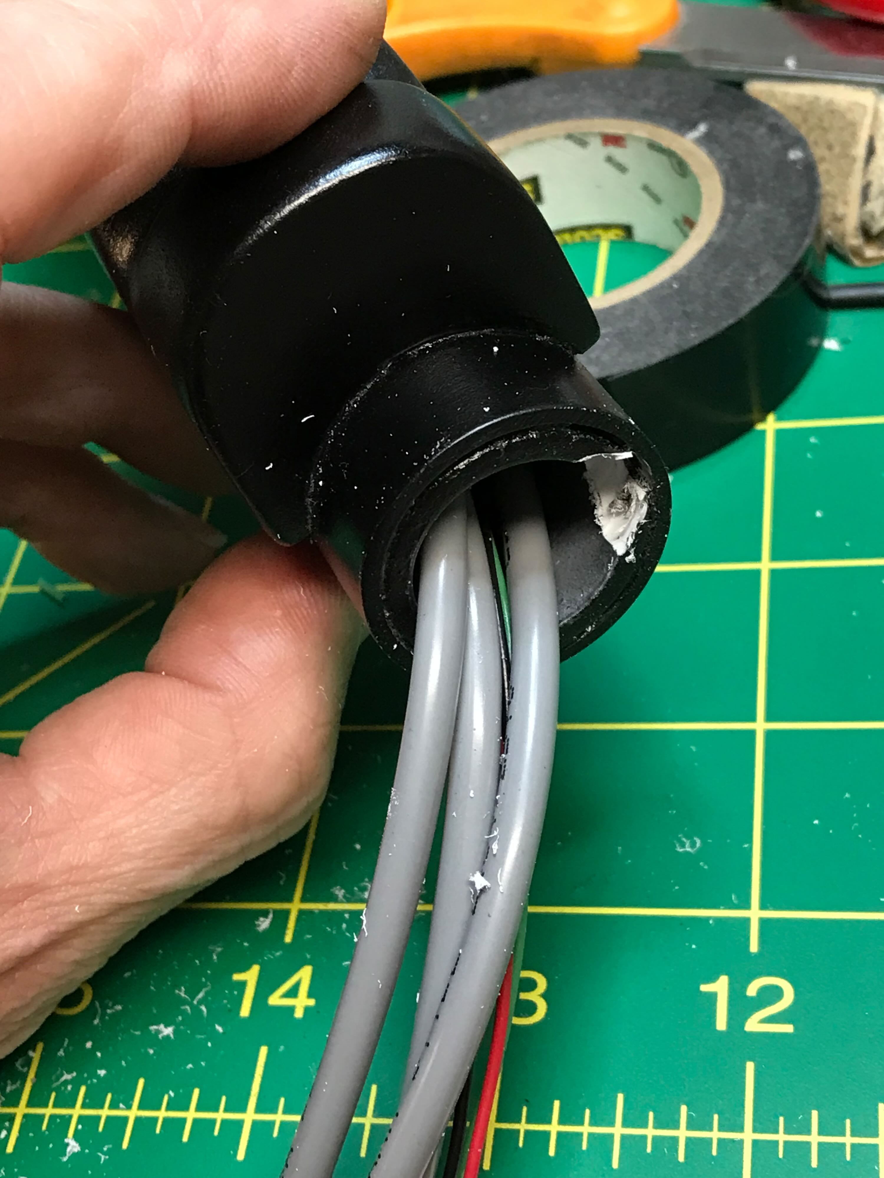
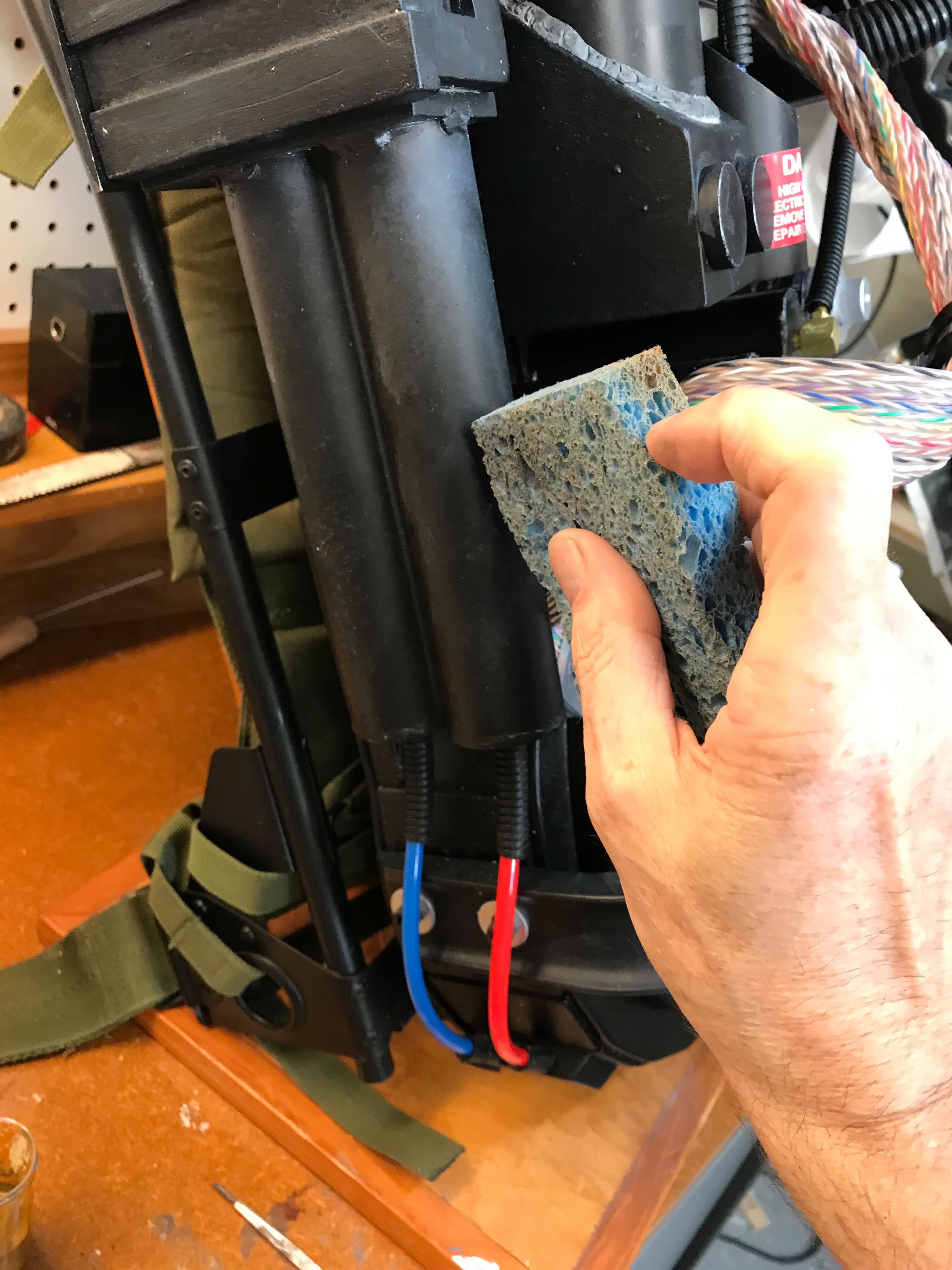
Wes had glued a piece of PVC pipe or something into the back end of the back handle. This constricted the hose too much, so I used a Dremel cutting tool to cut it open, then pulled it out with pliers, all while avoiding damage to the wiring.
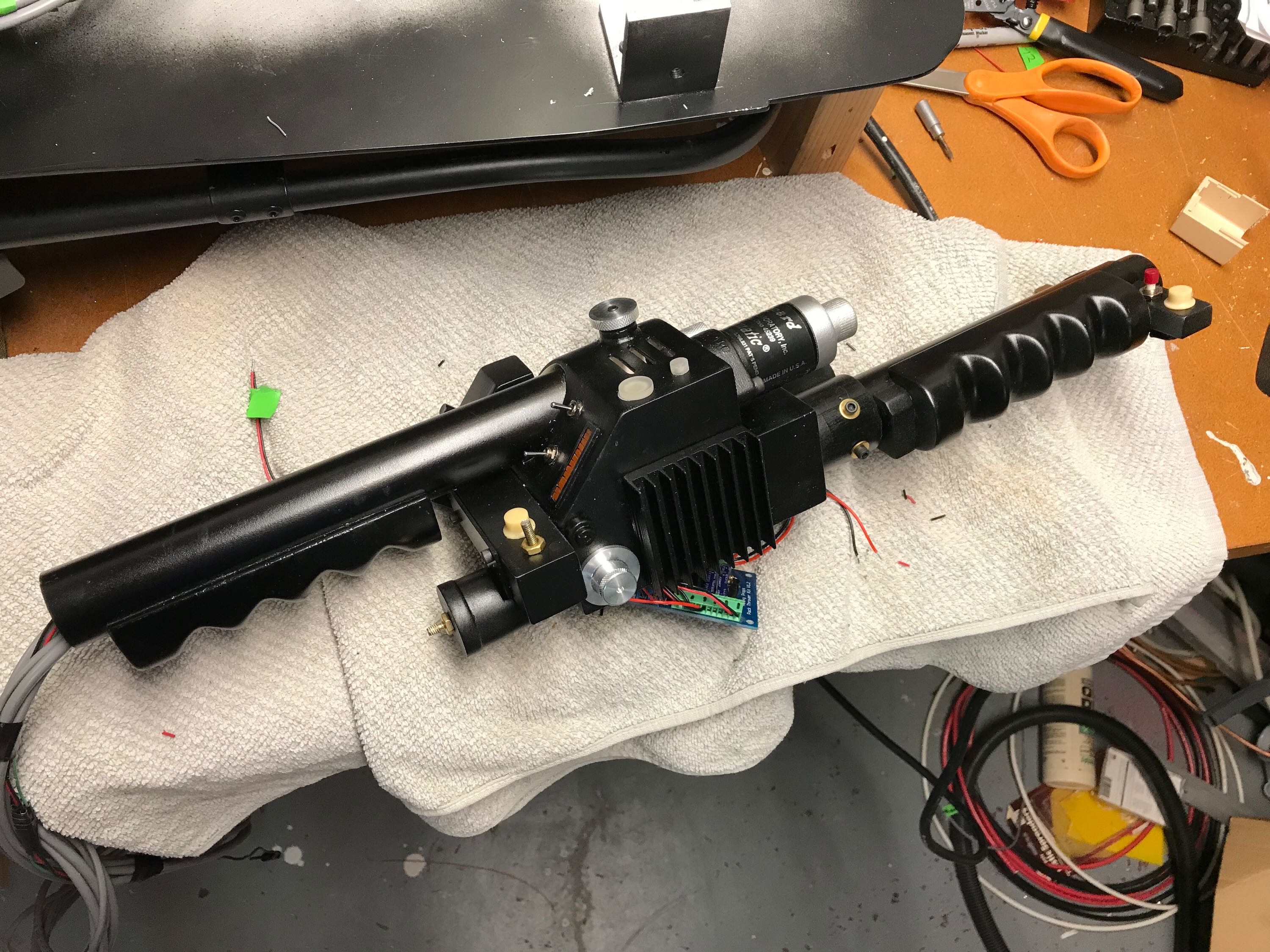
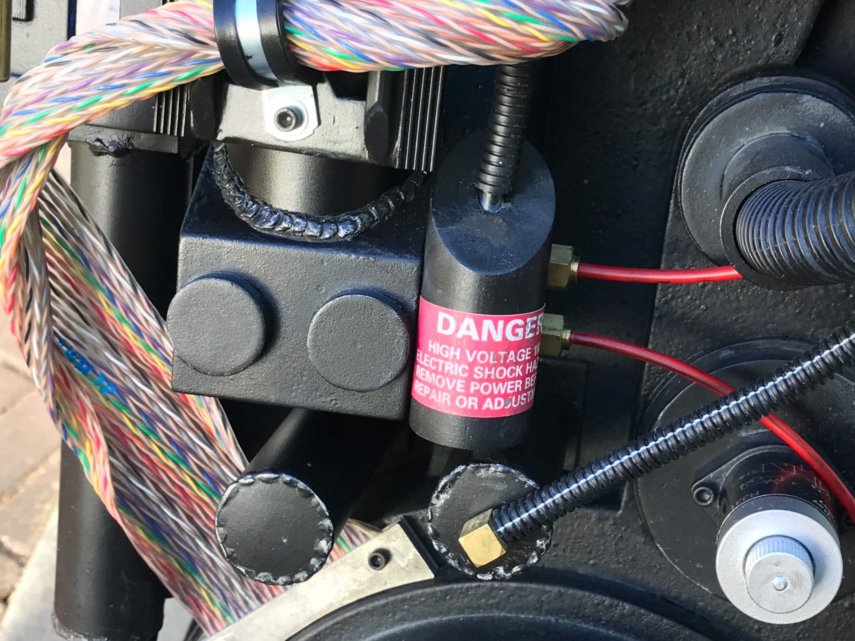
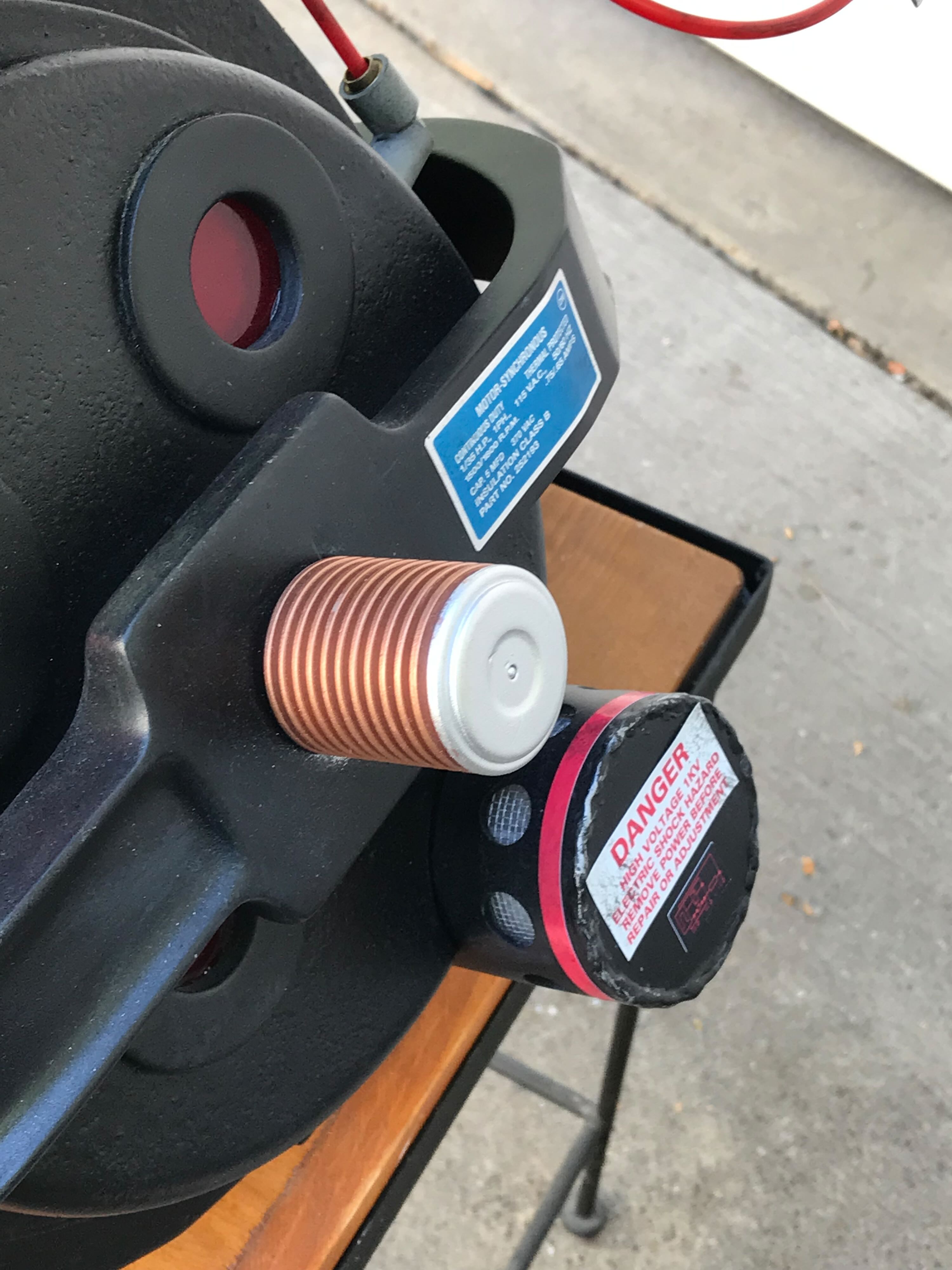
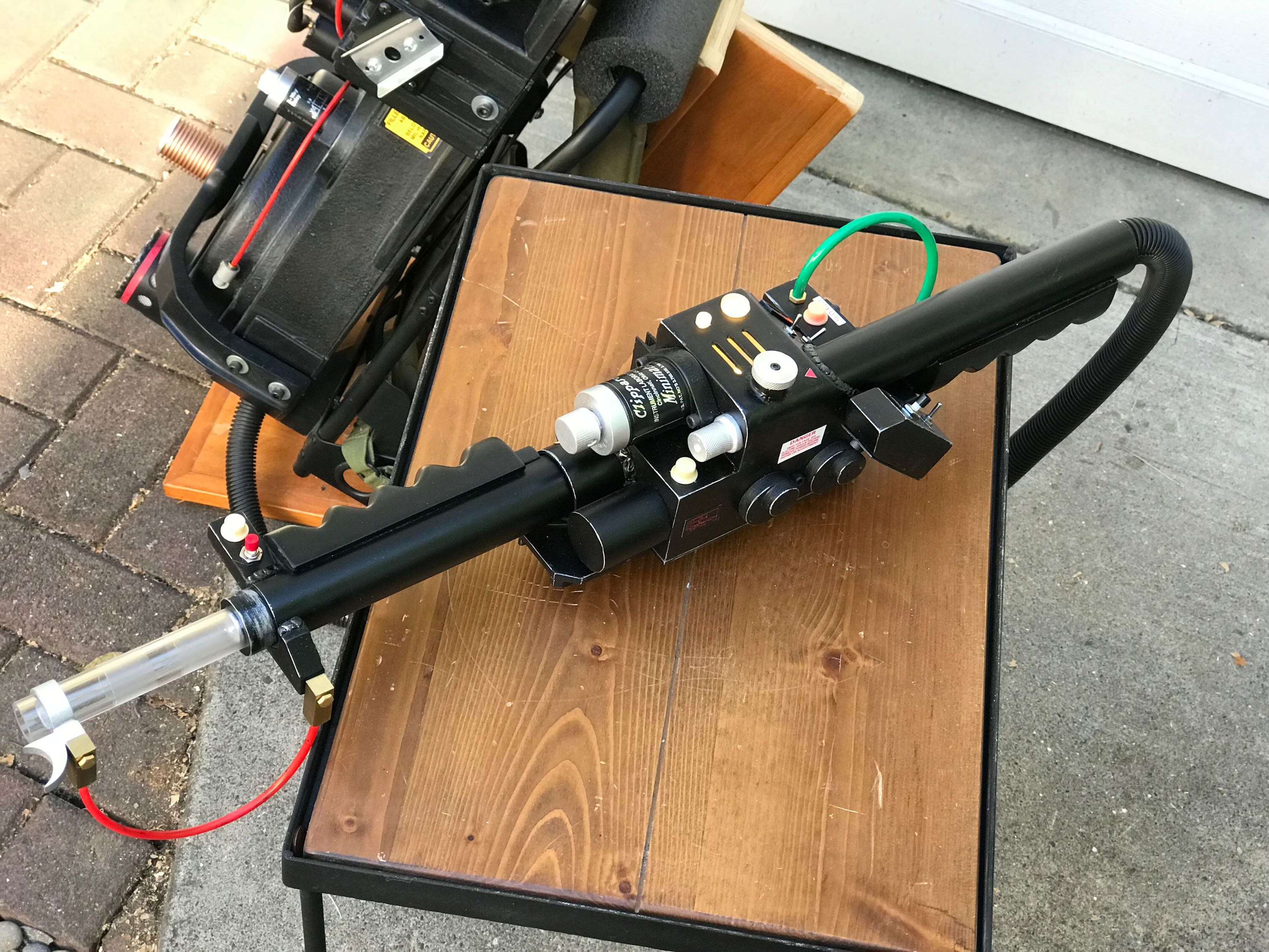
7/20/22 - Here’s the thrower, almost complete. I didn’t go to the time, trouble, or expense of finding every exact little connection, opting for approximations. I used brass nuts to evoke the connectors going to the green tube and simple flat brass washers on the front handle.
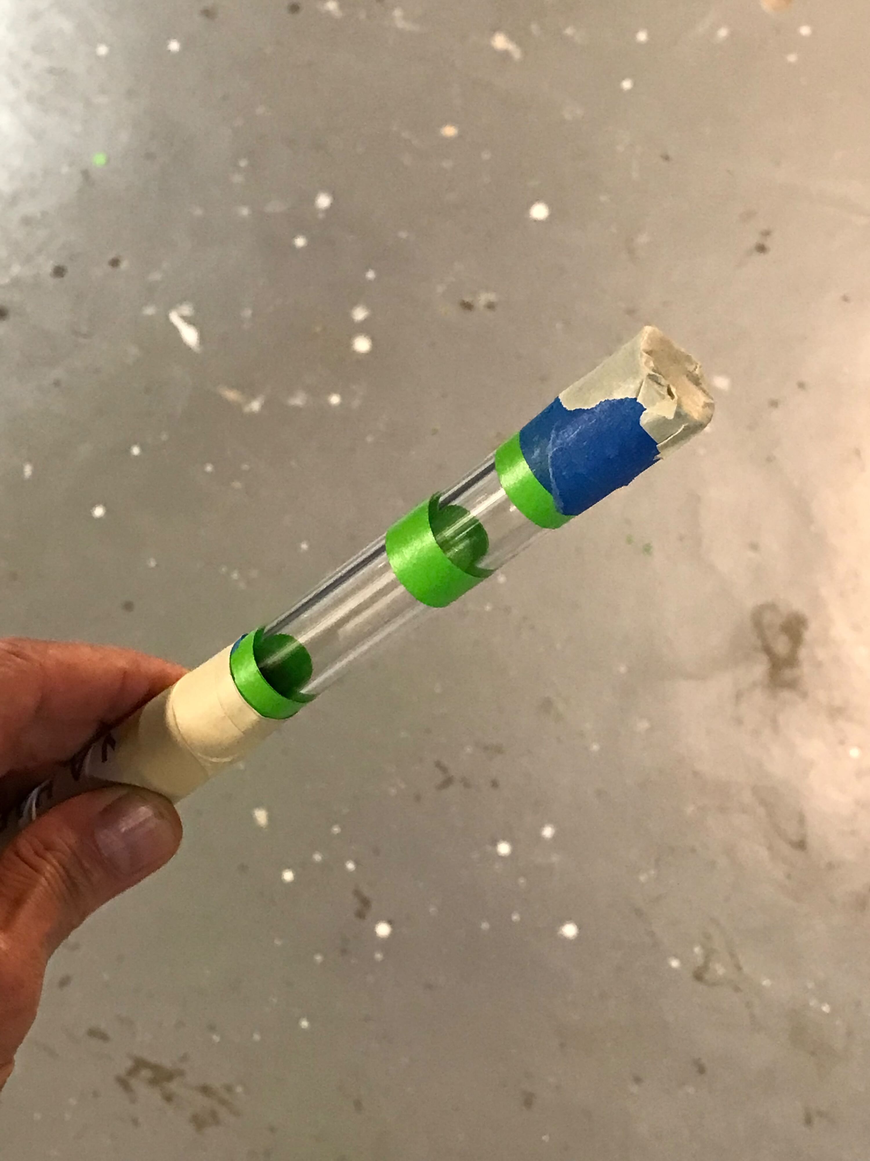
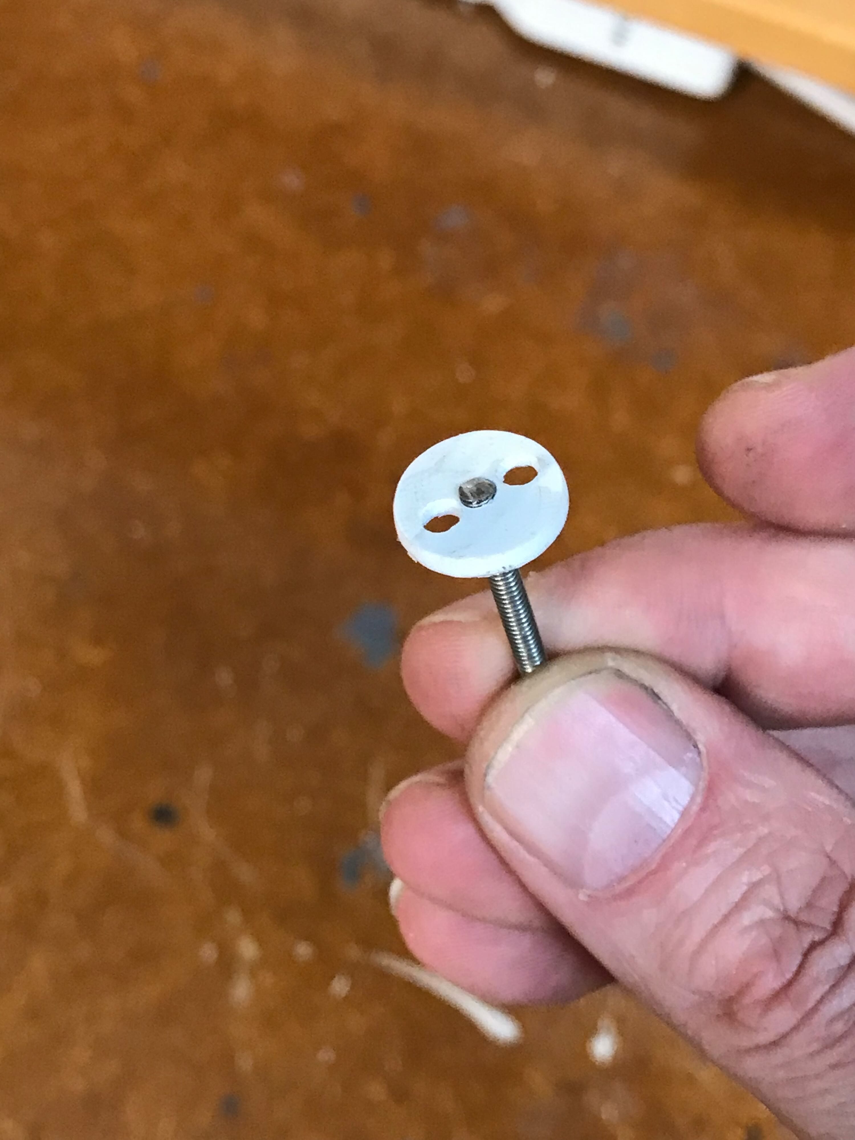
The Heavy Props kit came with two (blue and yellow) small, 3mm LEDs to light the gun tip. To mount those in the clear acrylic tube I fabricated a little circle from sheet plastic. I’d use an inch or so of 4-40 threaded long to attach that to a piece of dowel that would be held by friction within the tube.
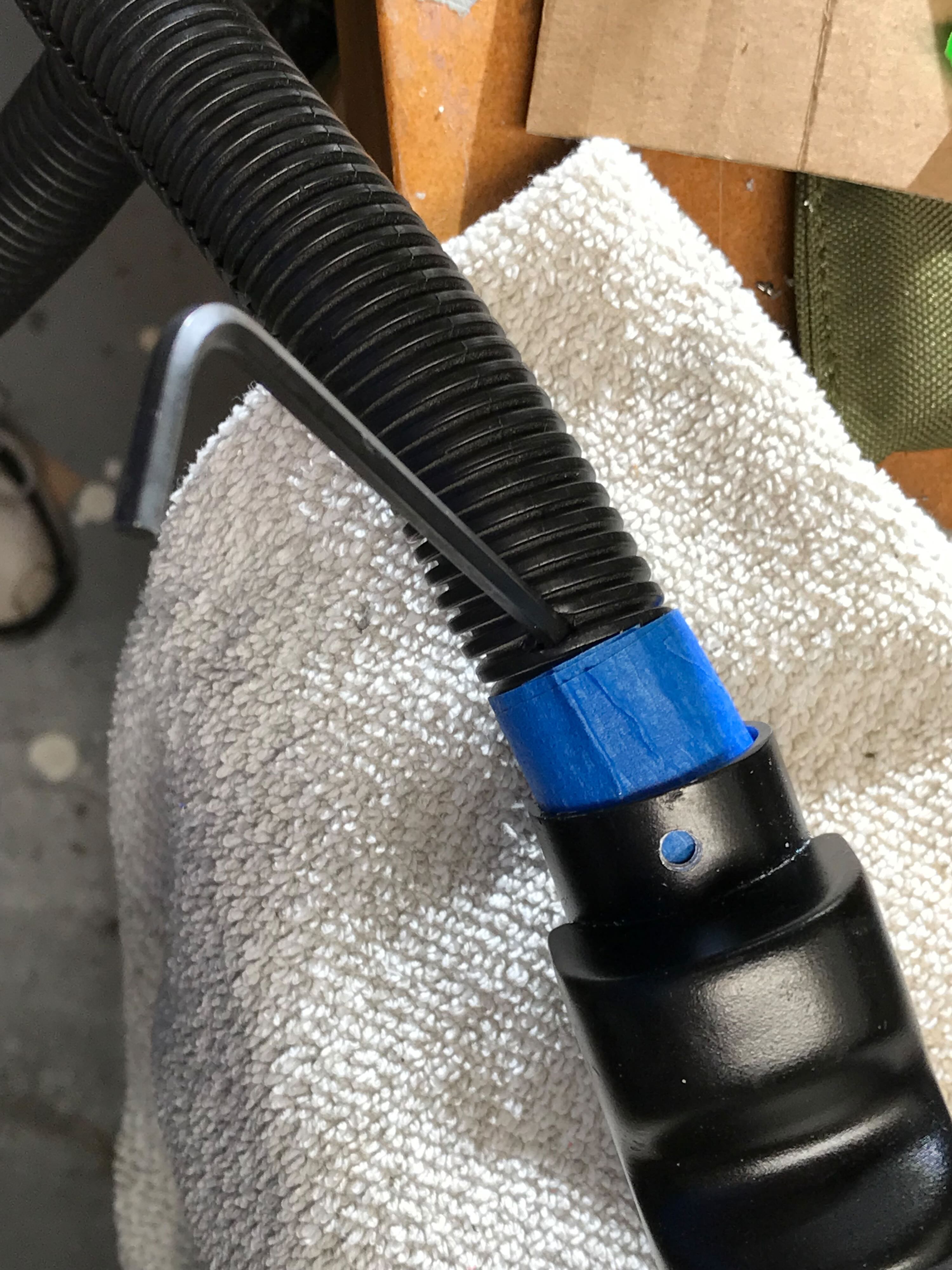
I drilled and tapped a threaded hole into the aluminum handle tube to mount a socket cap bolt to secure the hose. I used some cardboard inside the hose to help hold its shape and tape around the outside to help snug it into the aluminum handle.
I could have trimmed the wiring inside the shell a bit more after attaching the hose on both ends but didn’t want to take the time. As a professional 3D animator you learn not to put time and energy into things that won’t be seen. Especially if you’re way over budget.
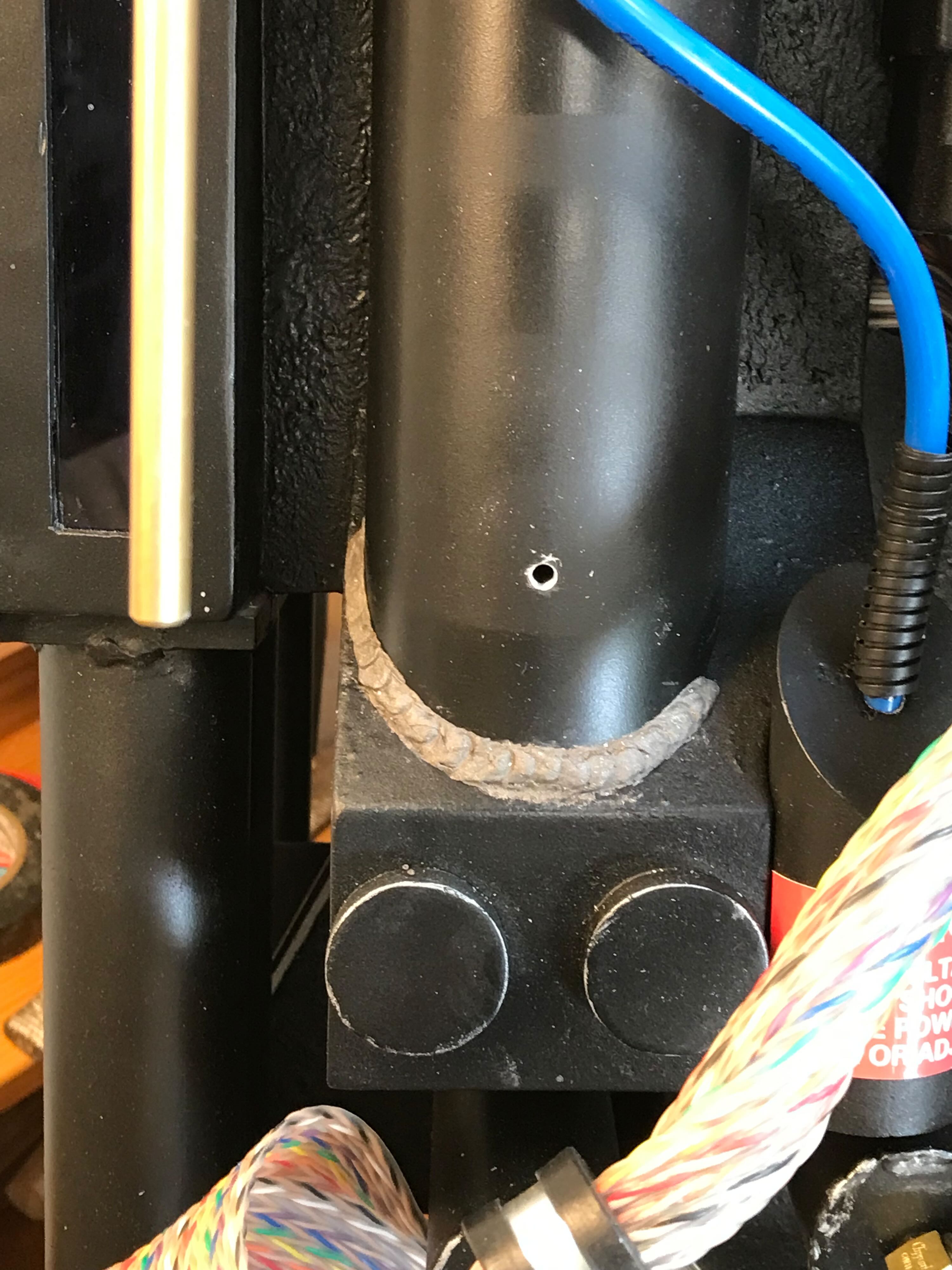
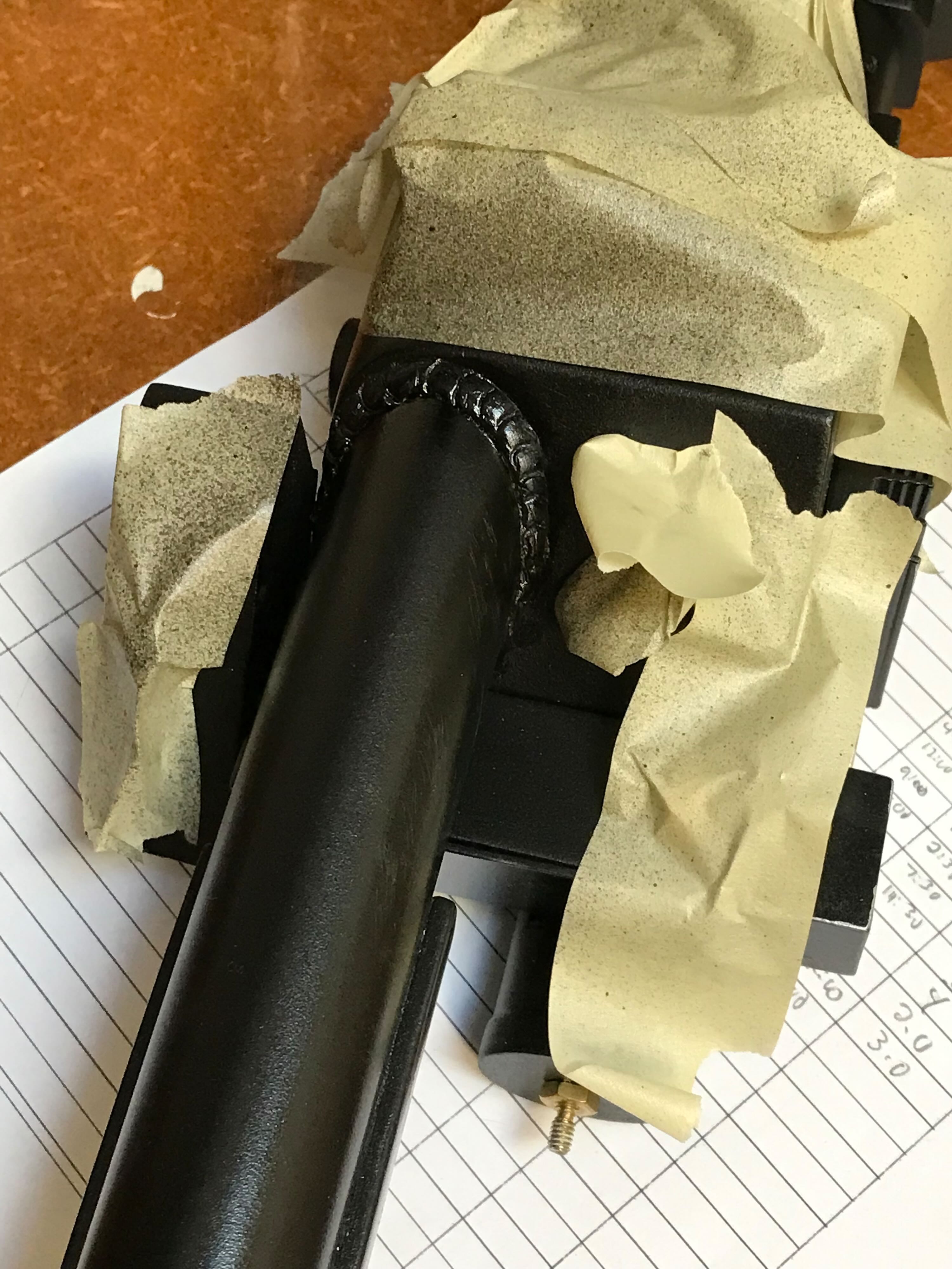
7/21/22 - I used the epoxy putty technique to create the various welds. I tried to use a little tool I’d fabricated to make the little circles, but I couldn’t fit it into the crevices, so I just used a paper clip. I think they’re beefier than they should be, but they’re not horrible.
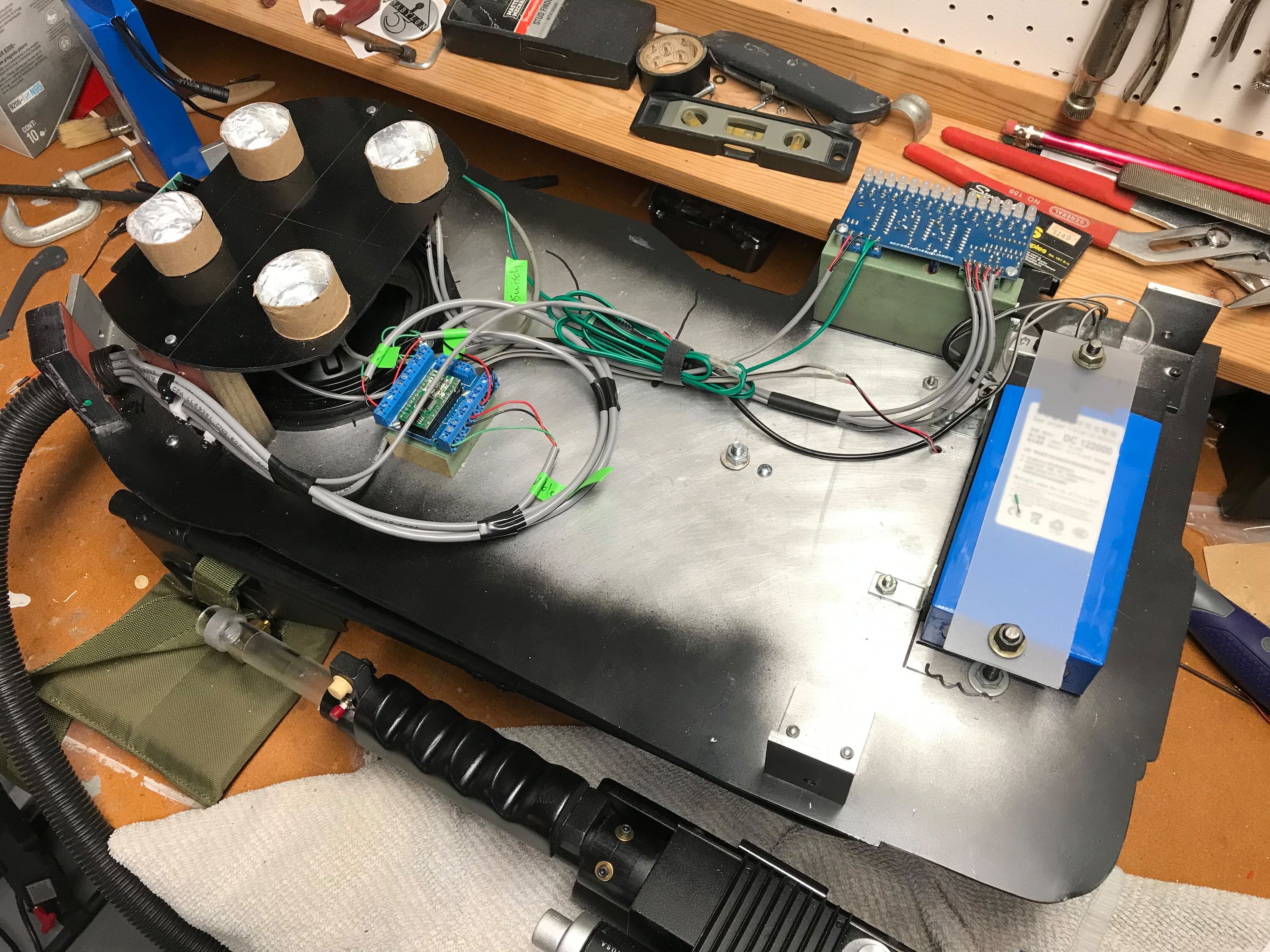
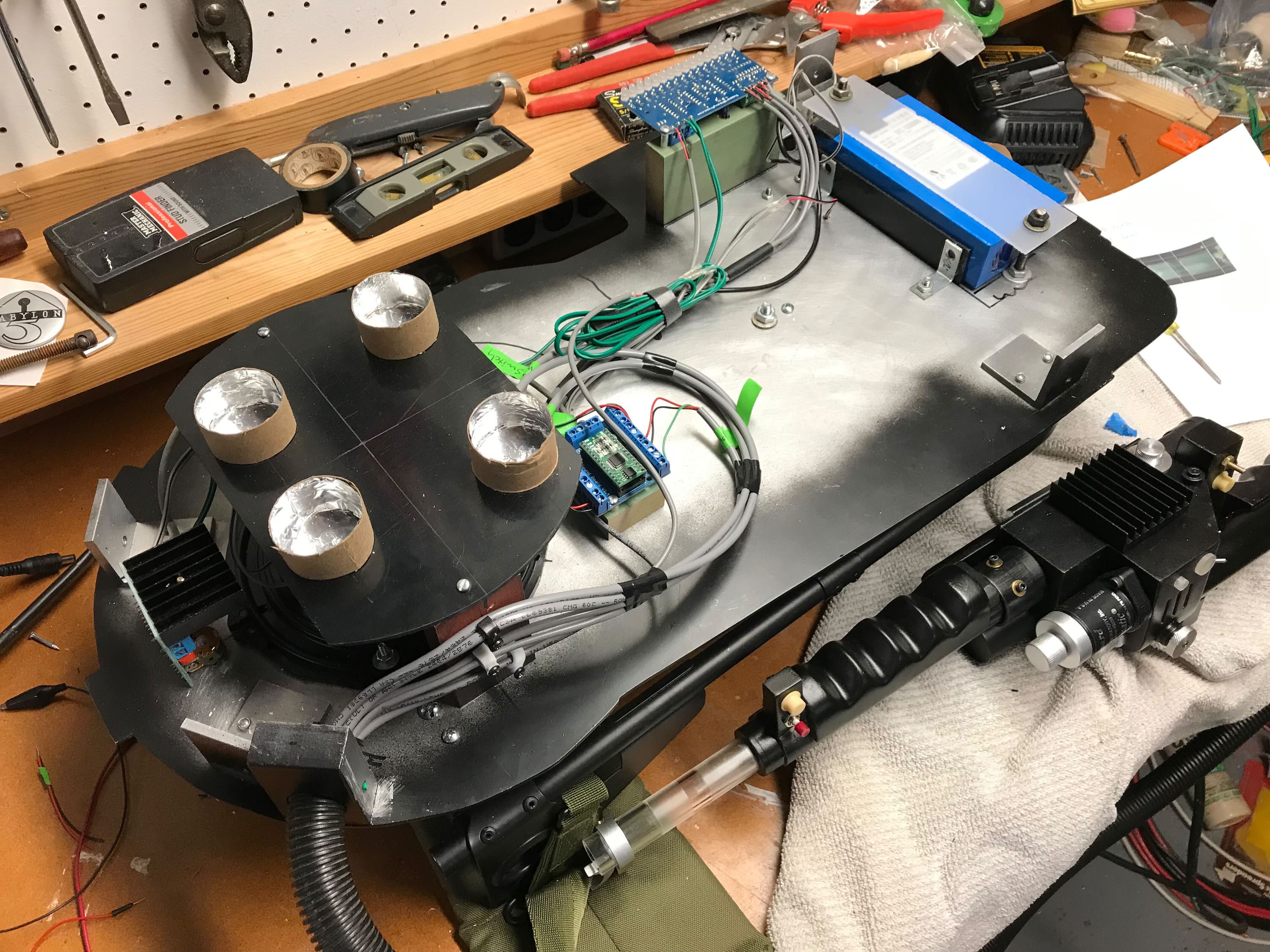
Just as I was about to finish I realized I’d mounted the Alice frame too high onto the motherboard, so I had to take that all apart, drill new holes, and move the frame down 1 1/4". This would raise the pack that much higher on the wearer.
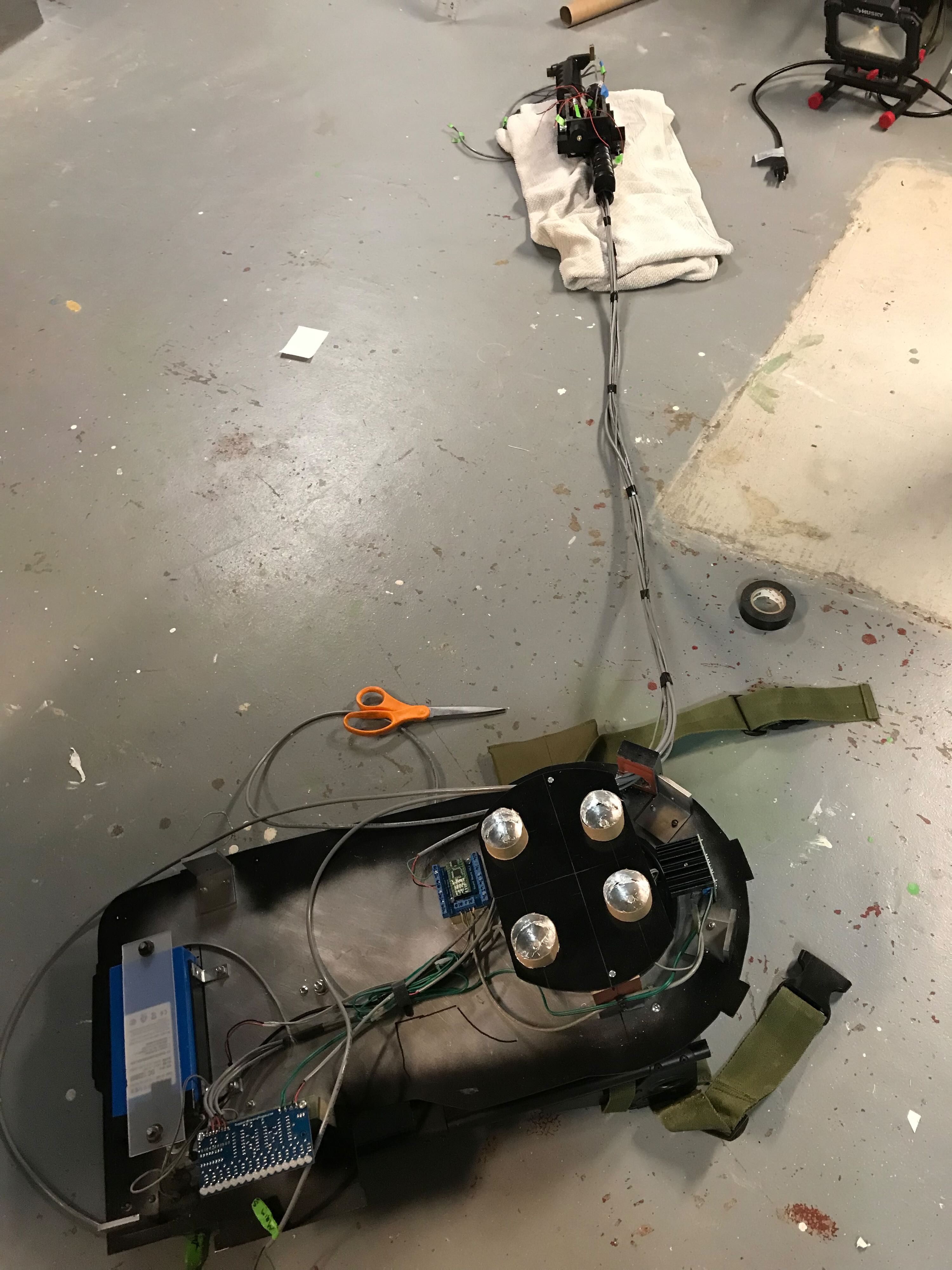
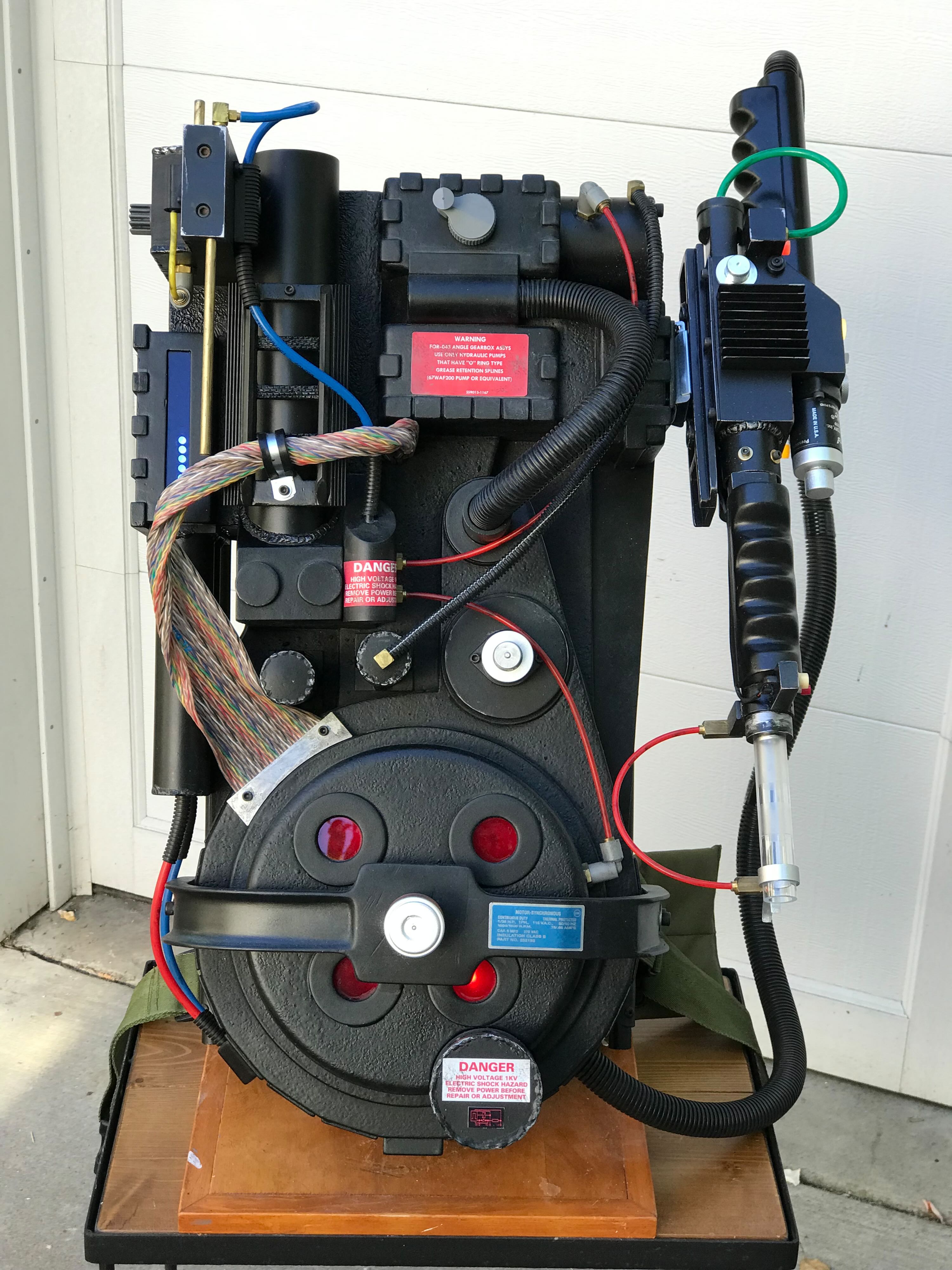
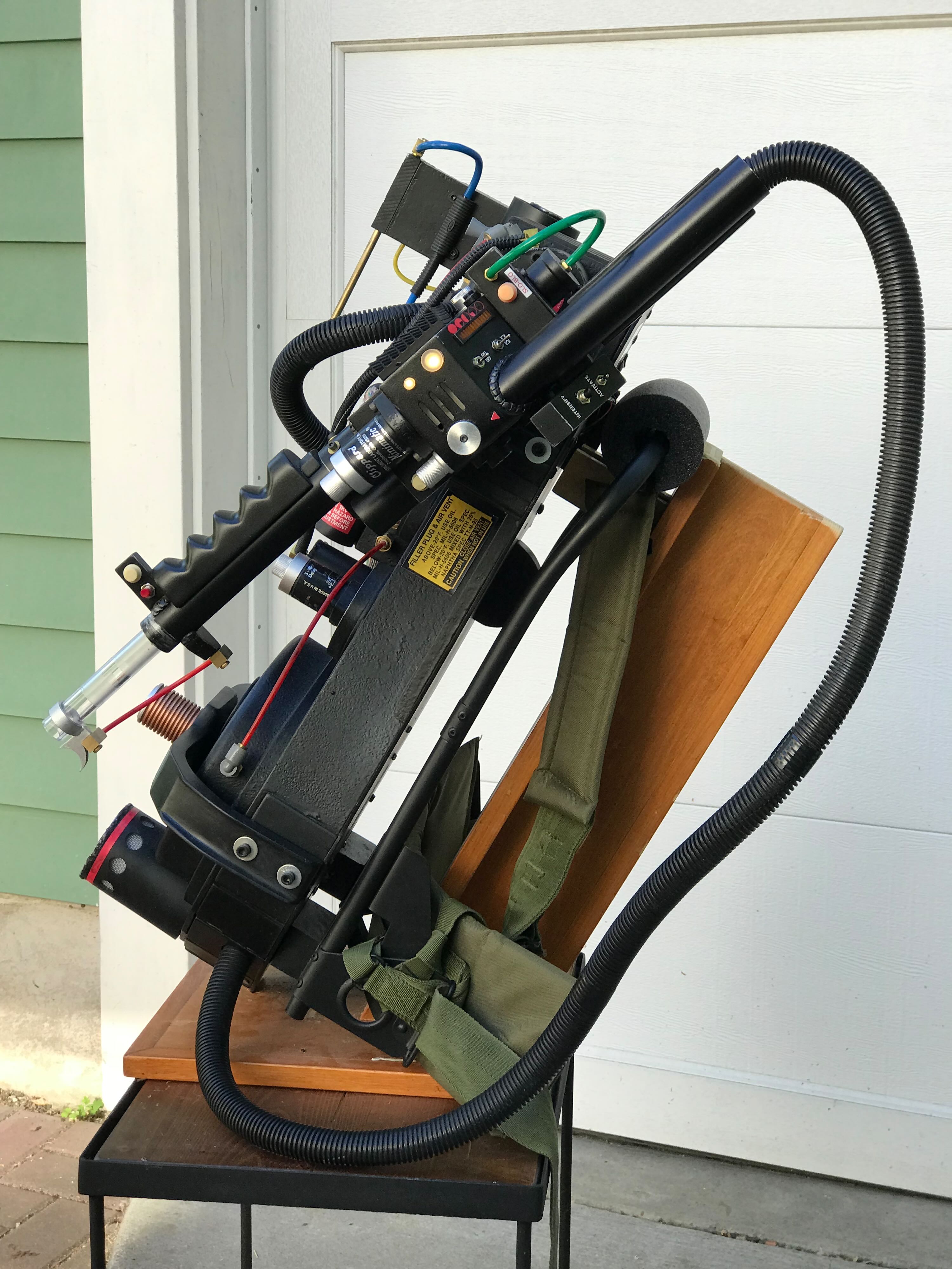
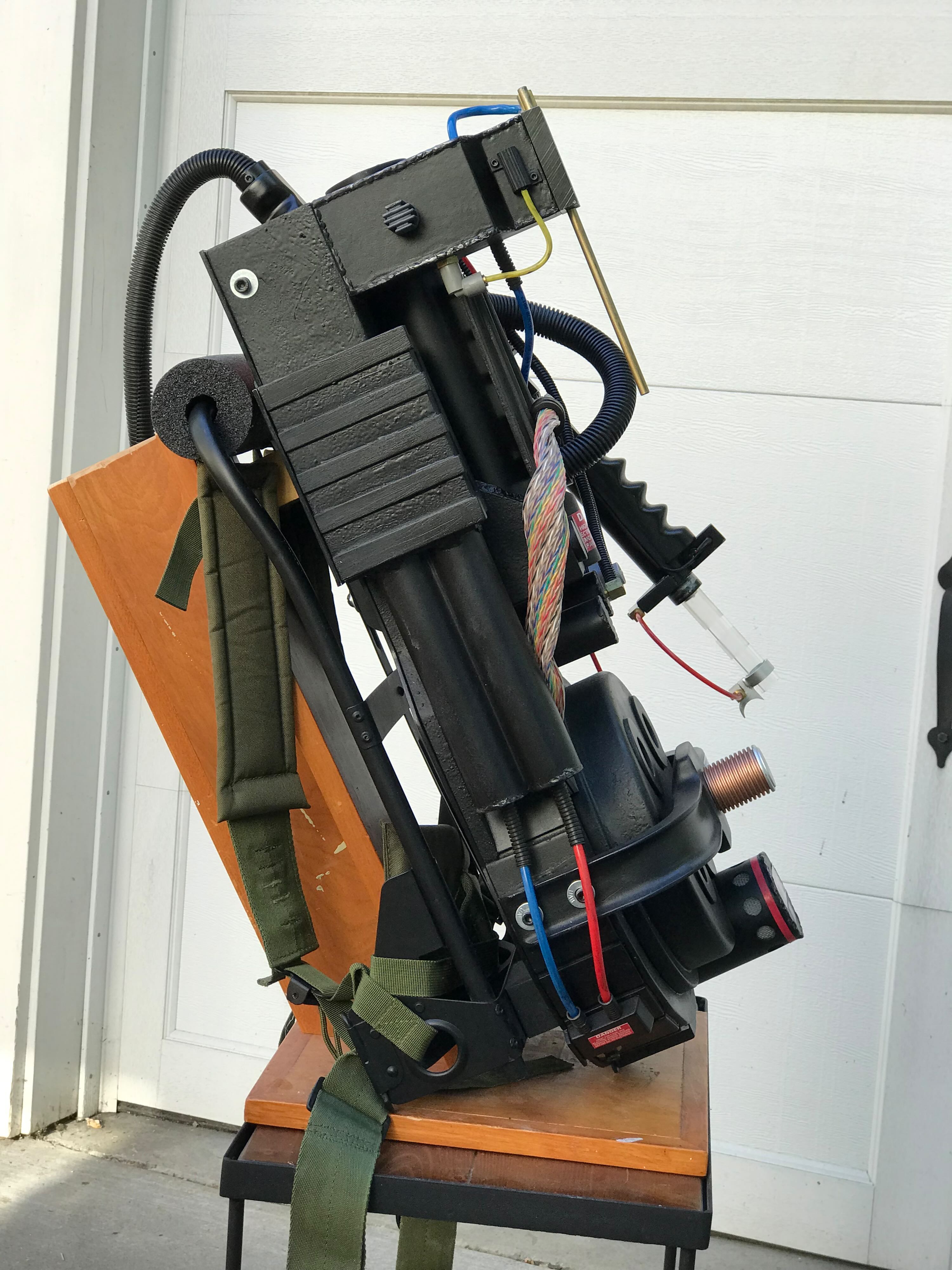
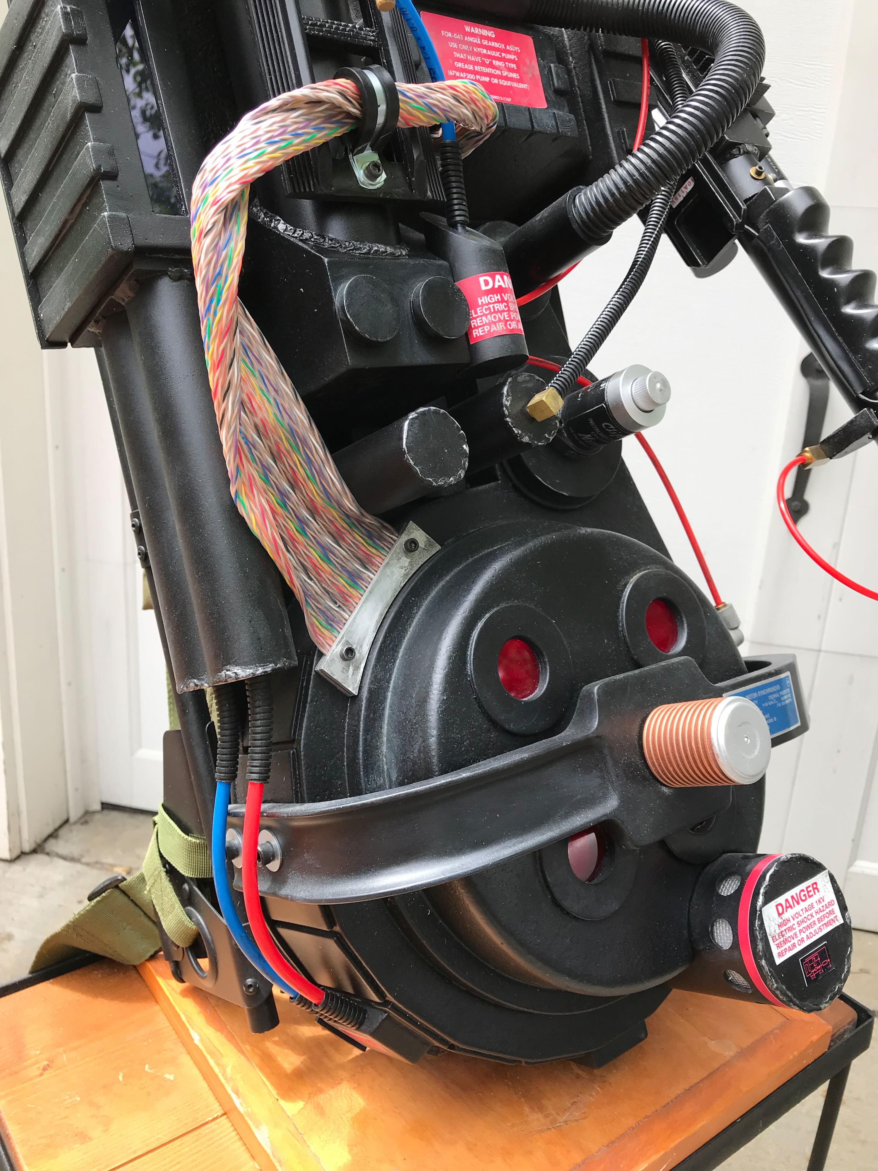
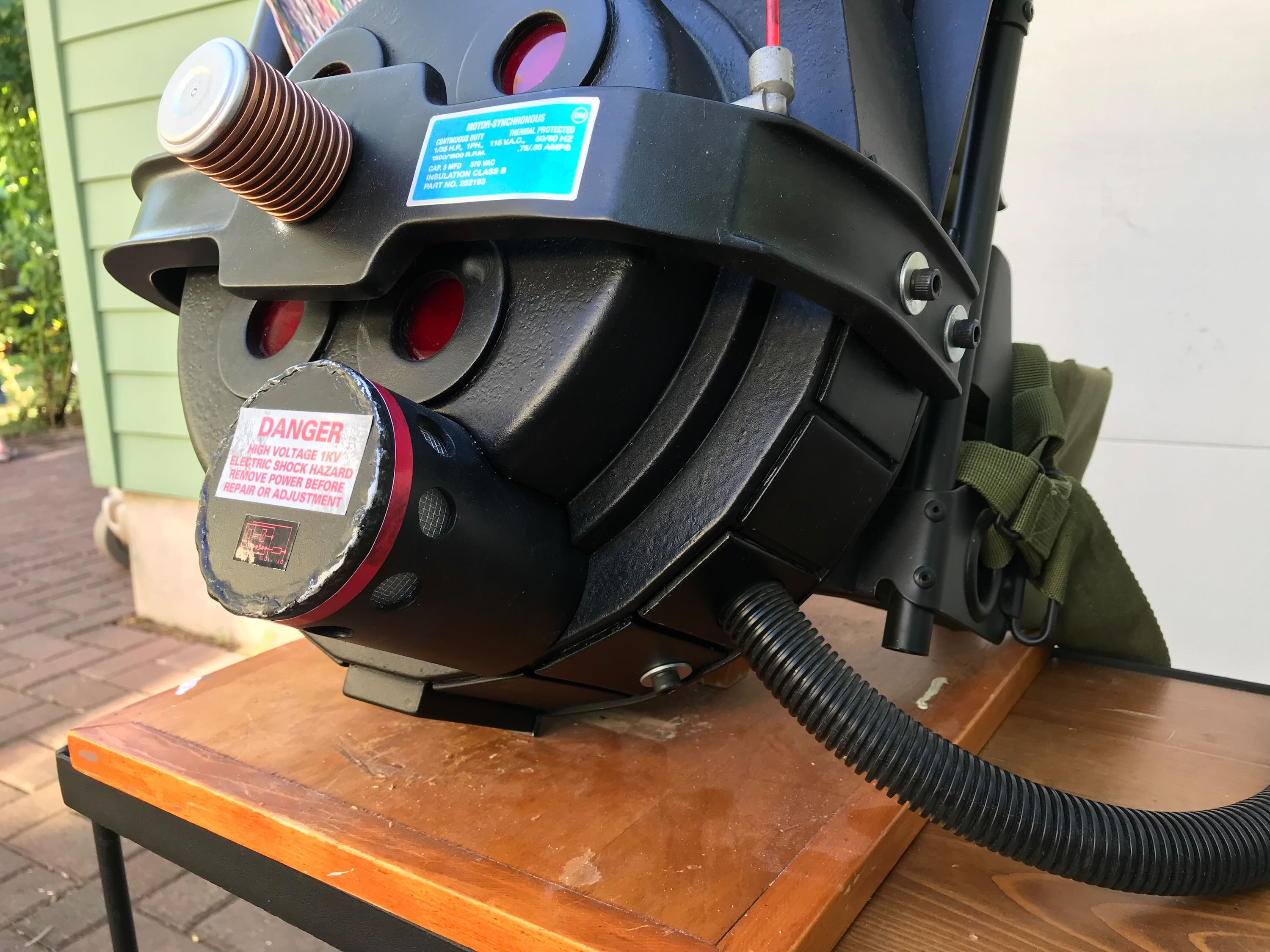
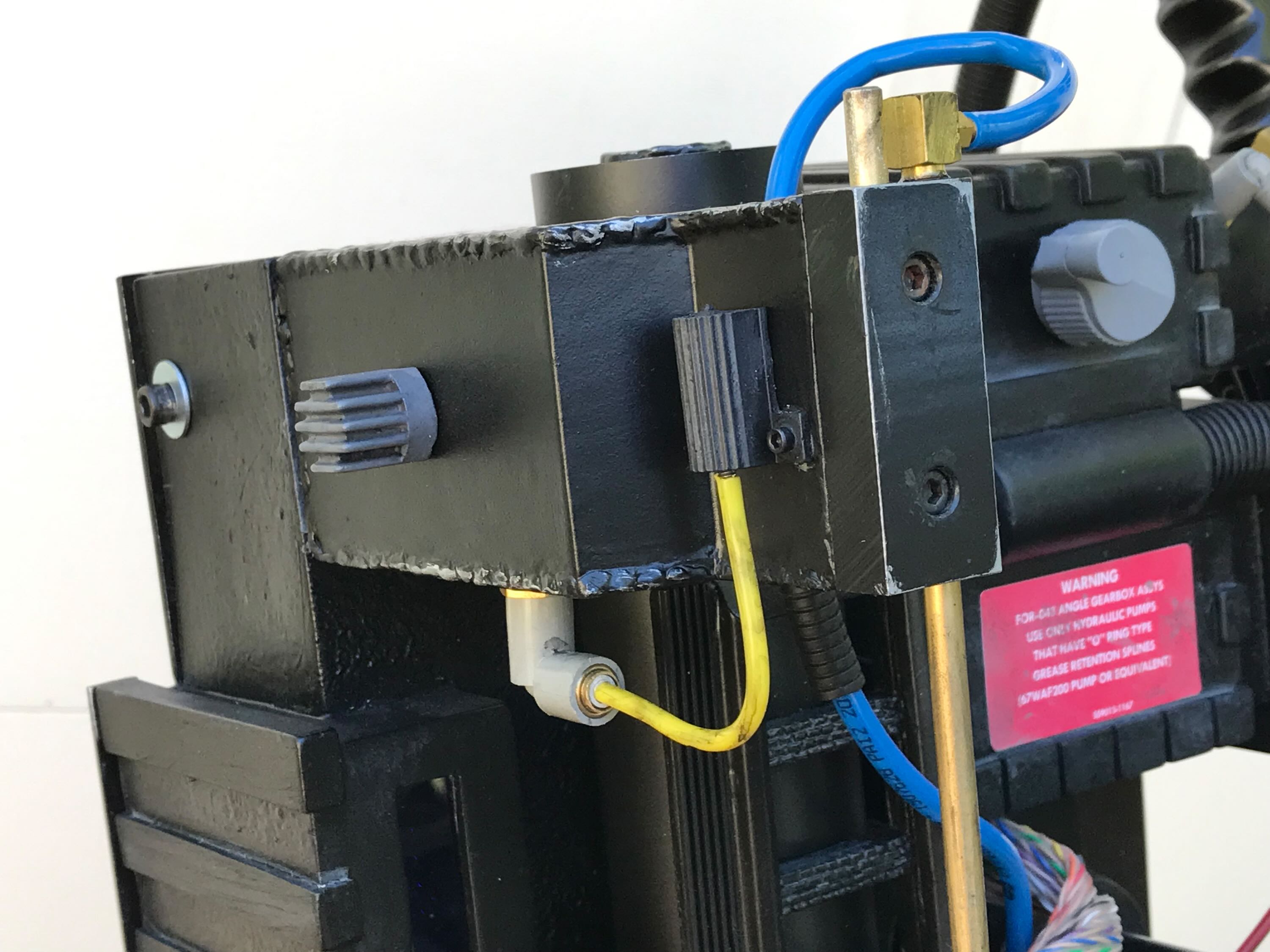
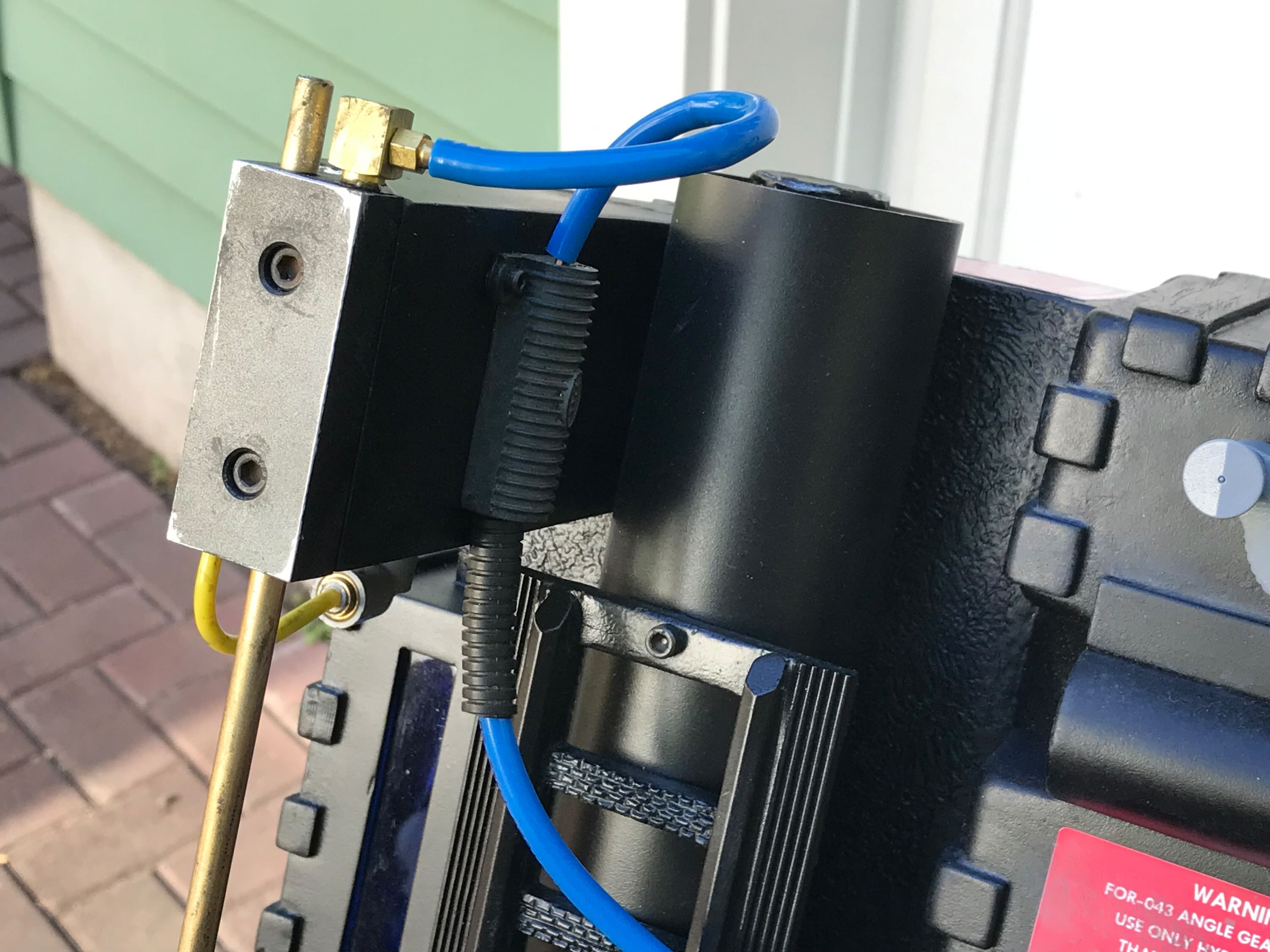
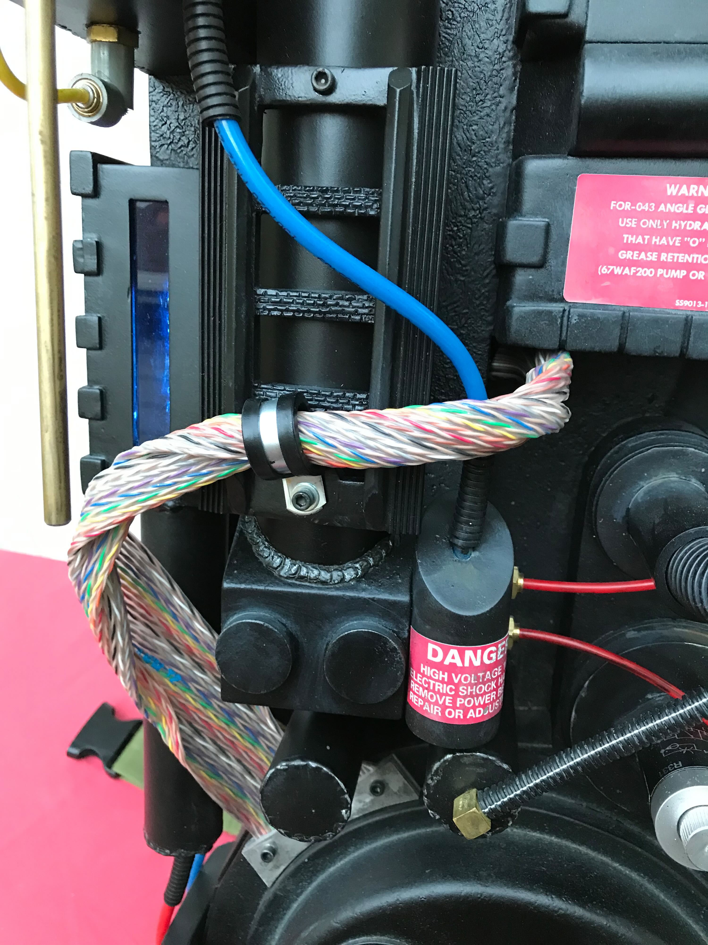
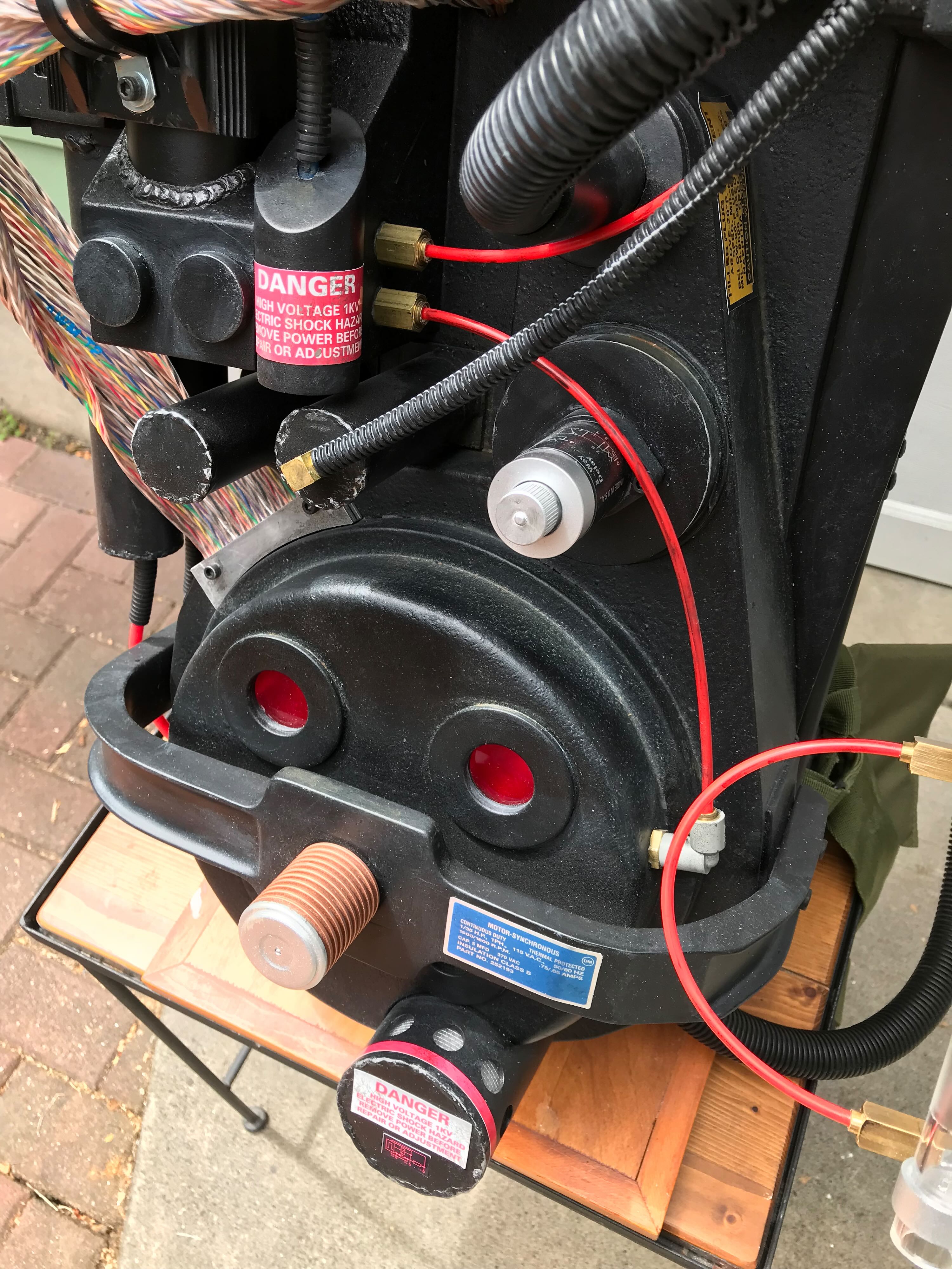
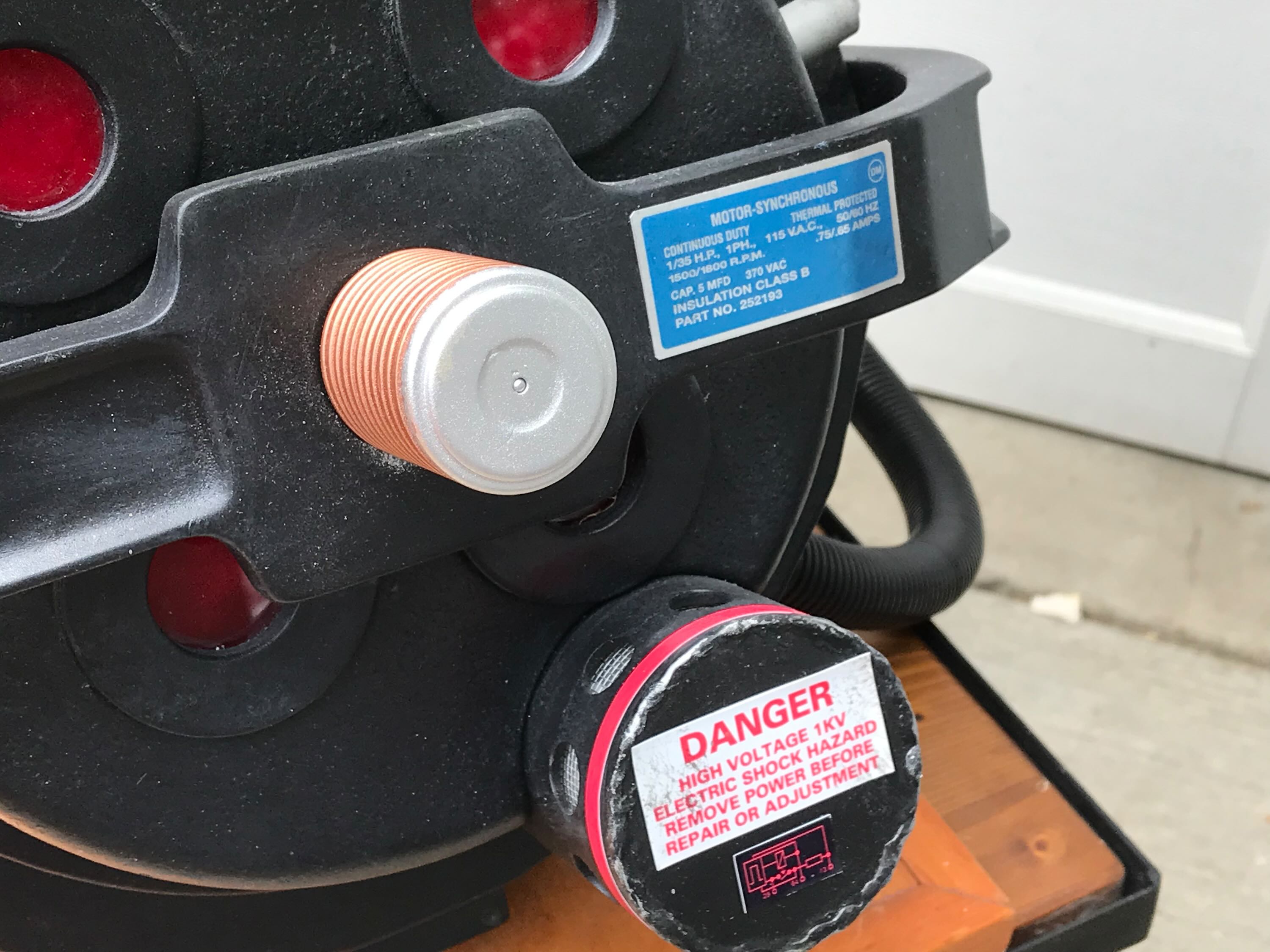
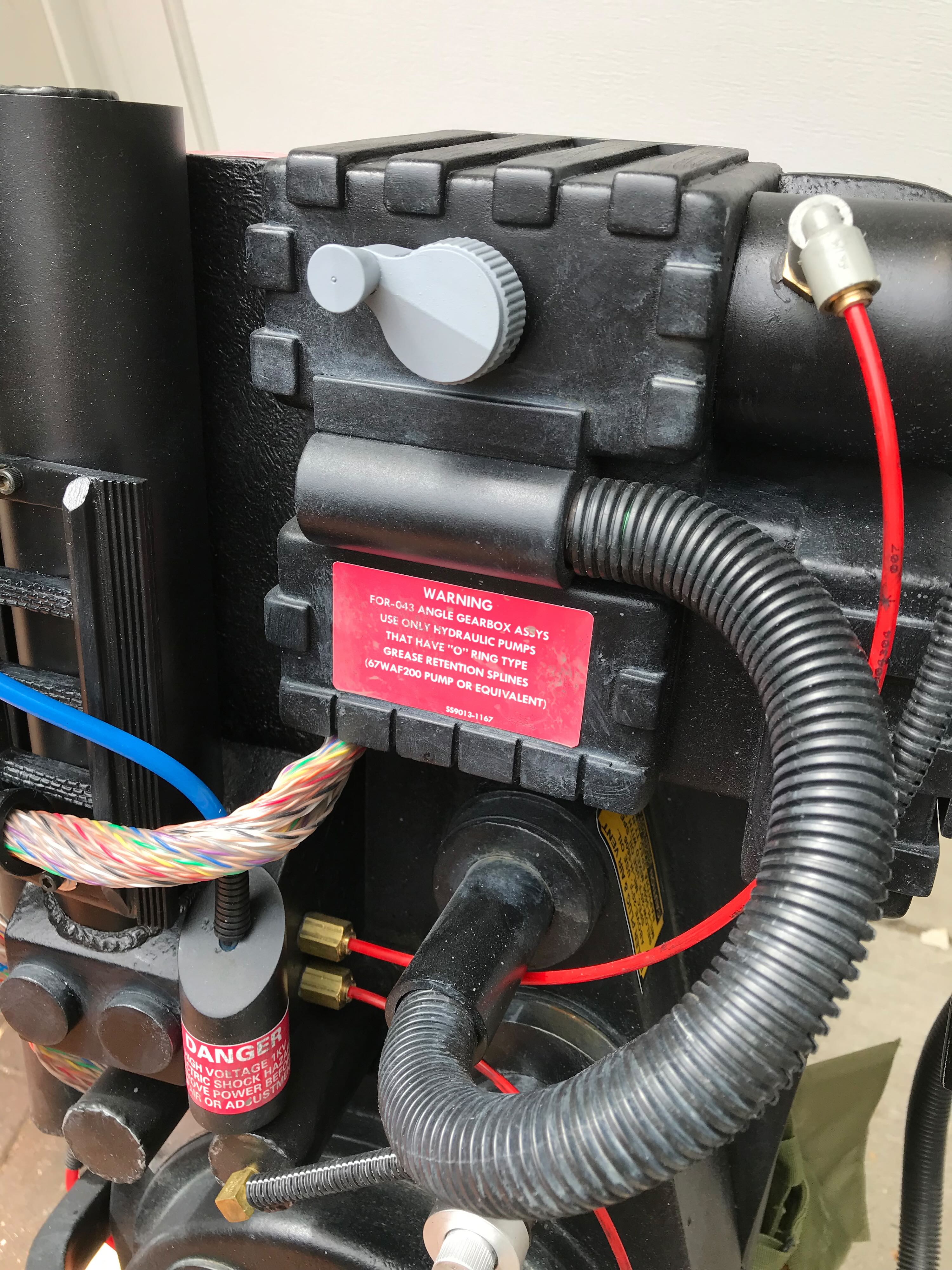
Here’s my 1984 scratch-built pack with this finished kit. I think my 38-year-old build holds up pretty well (especially to civilians). I definitely want to consolidate my ancient and separate lighting systems into a single modern one driven by a microprocessor and add a speaker and sound effects.
i need some help. I was gifted a benofkent shell but it has none of the holes in it pre drilled. I need to know where to drill all the holes and what cuts to make in order to attach all the pieces and stuff. Can you please help me??
Sorry for the late reply; I didn’t get a notice that someone had posted a question here.
Except for a few templates I got from the BoK Facebook group I just sort of eyeballed where things had to be drilled based on the scores of reference photos out there. This thread you’re posting on shows all of the techniques I used to put this one together. It’s not that big a deal if a few bolts are a few millimeters off. Good luck!
Can you send me any templates that would help me with the build? Where to screw holes and make cuts and what sizes the cuts and drill holes need to be and which parts go where?
Great job on the BOK build. I’m about to start one too for a fellow buster. I can see that you ran into some of the issues I’ve noticed about BOK kits.
Excellent use of the insert screws on the gun box, exactly what I was planning to do too as resin can strip over time. I’m a big believer in screws over glue as well.
One thing I’ve noticed in all the BOK pre-painted or finished wands is that they often do look liked they have been “caked” with paint. Yours came out so clean! I definitely plan to strip all the paint off the kit I’m working on as it came pre-painted by the original owner too.
Thanks for reading my build thread. I don’t remember where I first heard about those threaded inserts, but they worked perfectly. Even better, the little hardware store a block north of me had them in stock. They got quite a lot of business from me over the course of this build.
For all of the other resin parts I tapped I just tapped into the resin itself. That was mainly to provide extra strength on top of glue. With to gun box that plate has to be removable, thus the need for more secure connections.
Regarding the wand, AFAIK the person for whom I was building this had tried to paint it himself, but globbed the paint on WAY too thick, thus the acetone/steel wool strip job. That was gross and a drag and I never want to do that again.