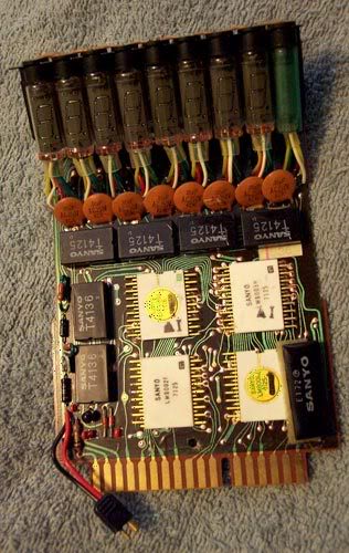
OK here is my build so far - using the measurements and Sanyo circuit board images from this forum:
Green base board:
With printout of circuit board glued on it and sealed with varnish:
Nixies all ready:
Starting the Nixie “caps”:
I gotta take some height off the “legs” of this methinks! This will be sprayed black then glued to the top of the circuit board, then the Nixies glued on, wires put thru the boards, then the capacitors added. I didn’t copy this bit mega-accurately for the simple reason I wanted it to be stiffer and more robust, cos I know how clumsy I am :oops::oops: and I could imagine Nixies pinging off at every troop!
The white chips will be styrene with very thin brass tubing glued to them for the chip “legs”, then the whole lot glued to the board. The black chips will also be styrene, and there will be random capacitors and other electrical gizmos added where appropriate.
I must also show you a pic of my fellow UK Buster Chris A’s board build, which is excellent!
Have yet to glue down the glass Nixies, also have to cut out styrene fake “chips” and put the brass “legs” on them. Then add some more capacitors and stuff, and make the smaller seperate part of the gizmo that the phone cable will attach to.
Be warned I flipped the image so it was reversed, else the white chips will end up on the wrong side - you can see the solder marks where the chip “legs” go, and to recreate the original board you have to flip this image.
1mm brass round wire from a model shop, bend into an elongated “staple” shape and push thru holes drilled into the circuit board. Araldite in place on the reverse of the board.
Print out a scan of the white circuit board chips, glue to white styrene, then Araldite to the brass wire.
I’ve got a selection of resistors, capacitors and greeblies to glue on next but am having probs finding some small black old chips - anyone got any spare? I need some for the smaller circuit board part too Help!!!
Main board finished! Mocked up the black chips in Photoshop, printed out and glued on 3mm perspex. Yeah I know the verticla chips have a different number on but I’m severely running out of time before my first GB event at end of April, and it’ll be covered by the tape measure holder anyhow Random resistors and capacitors glued on also.
Here is the smaller board which is complete but for a couple of old chips I’m waiting for, from y mate - then all done wooooo!
What does everyone use to clip them onto your belt and to hold the main board in the tape holder?
PS Here are my Cyclotron LED holders that I dreamed up - just slot the LED in then glue the red perspex to your pack inner and hey presto.
Hye Gixer, I just wanna say, awesome thread. Very cool progress build for an item that is nearly impossible to find. Great work!
I was also wondering if you happened to get your Clippard valve?
I also had a concern with how to mount the LEDs for the cyclotron. I have a question about your method however. When one light is lit at a time, does the light wash into the surrounding lights since you have nothing to separate the light? Let me know, or post pics. Cool idea.
Hope you got that valve through the friend of yours. I would like to know.
Yes I got the clippard valve via Chris A, not sure if he ordered from you or someone else? Anyways I got it and very tummy it is too - makes the resin one on my gun look crap - methinks I’ll have to get an original of that one next
Regarding the light mounts, if the light interferes with the other lights I’ll just Araldite a black bit of perepex on each side of each mount so the light’ll be contained better.
well… one could go and have the PCB etched at some PCB company - around 2.50$ per square inch. There would be some work involved into creating the gerber files, but its totally doable.
I’d say not worth it for the attention that the belt circuit would draw from Joe Public - they focus on the Proton Pack most of the time and if they glance at your belt circuit they’d probably notice the Nixies and large capacitors and not much else
Not meaning to hijack at all, but I made a PDF for myself to start on one of these using Gixer’s awesome method, and thought I’d share with anyone who might want it.
Printed out, this should give you all the images for 2 boards. I color-shifted parts of the board to match the brown boards I’ve seen in photos. I cleaned up and redrew the tops of the chips and included those with it as well. I also extrapolated measurements on the riser piece at the top of the board from the photos posted of actual boards and Exoray’s measurements to give you a template for that piece. Enjoy.
Very nice! But is it on A4, doesn’t look like it in which case it may not print correctly Also the two black chips that are down the side have a different number on them




 Help!!!
 Random resistors and capacitors glued on also.