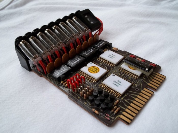
Alright. Here’s what I would like to do. I am planning to etch a better belt gizmo board replica (hopefully fo sale), where builders can actually solder components onto the board securely. I’m not a big fan of the alternatives (printing out the design onto wood or card, or the plastic castings where you have to draw the leads on). I would like to make something that is as close to the real thing as possible.
Here’s my criteria for the build.
The board will be the “transistor” version (with the transistors running down the side instead of IC’s), as this seems to be the most accurate board type. I’m open to discussion here.
The board will show the proper front side of the calc board. I found it trick to put together a mirrored board, as it never seemed to look right during assembly (because it was backwards).
The board will be double sided, so that builders can properly solder from the reverse. I had a single sided etching, and it was very difficult to solder components on. I will just be making the pads on the reverse side (not the full design. That would be pointless).
I’m not concerned with the material the board is made from. I found that the board can be painted with glass paint, and then rubbed off of the leads. This has a good, if somewhat ghetto, look to it.
So here’s what I need some help with. I’m looking for some high resolution ref photos of the calculator board, as well as some measurements for scale. I will be recreating the board in AutoCAD (I’ve designed boards and other things in AutoCAD before). Where components are in the way, I will probably be winging it, but the better the photos I can get, the better board I can make.
I hope I can get some help with this. I haven’t seen many busters with Belt Gizmos, and I hope to change that.
I’m still looking for photos. Specifically, I’d like some up close photos, as I can’t make out some of the details on the few usable pictures I have found.
Wow. Those are some great, clear shot. A few more of those, and I’ll have what I need. Thanks a bunch for pointing that out to me. I must have missed the thread in my search (the Equipment page one is great as well).
I can lend some insight on his build. Though i’ll let him know about this and see if I can get him to reply to this. This is a very old post at this point so forgive me if I get some of these details wrong, but we each made one of these using the same method. The construction of it was a styrene sheet that we cut to shape. We based the sizing off Nick-o-Tron’s resin kit that both of us had purchased but neither of us ended up using (they were the stunt boards). We found a photo of the backside of an actual ICC-808D board online and sized it accordingly. We then flipped the image so that all of the leads/contacts were facing the proper way and then printed them out. The prints were then spray glued to the styrene. The copper contacts were traced over with using a gold paint pen. Then all of it was treated with hefty amounts of clear coat before any of the parts were added. The board was drilled with a dremel and then the parts were glued into place. The back rest for the nixie tubes was used from Nick-o-Tron’s kit. It was a very convincing build and he paid very close attention to details. Anyways, I hope this helps.