I already posted this in the sales thread but it should probably go here too. Here is how the mechanics work.
Heads up, tutorial for the mechanics!
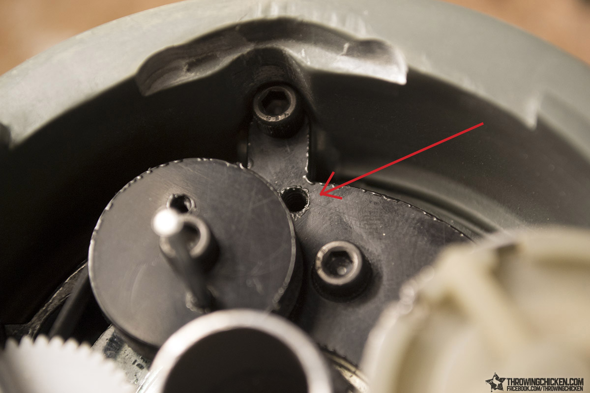
Hey all, I wanted to give you a quick tutorial for the mechanics of the Gigameter kit. Most of the kit is pretty self-explanatory except for this part.
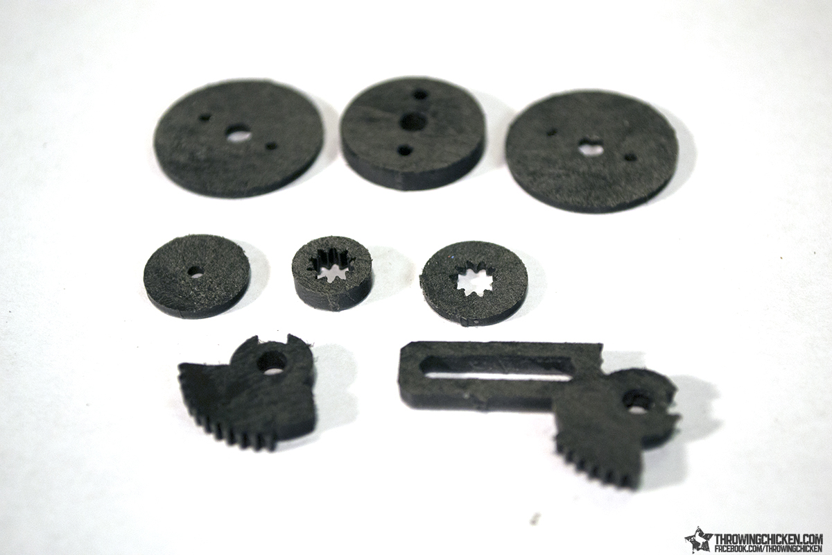
The black plastic pieces are cut from Delrin, which is a strong machinable plastic that they often make gears out of. It is also designed to withstand staining and gunk, which makes it a tiny bit more difficult to glue together than say acrylic. Fortunately the solution is simple; just sand the surfaces you are going to glue. The glue I found most effective was superglue, and in combination with scuffing up the surface results in a strong bond.
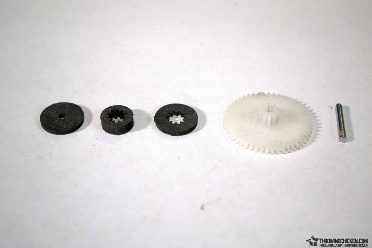
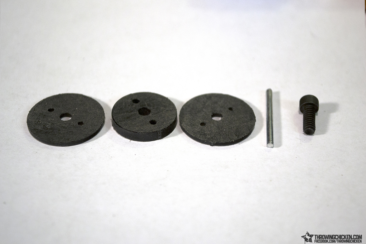
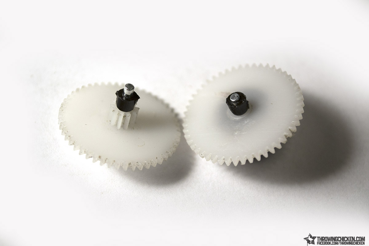
Here I have laid out the parts needed for Gear B (There is a Gear A, but it doesn’t require any direct modification). From the left to right, we have one of the small 1/16” thick laser cut discs with the 2mm center hole, the small 1/8” thick laser cut disc with the gear shaped center hole, the 1/16” thick laser cut disc with the gear shaped center hole, one of the white plastic gears, and one of the shorter 2mm axels.
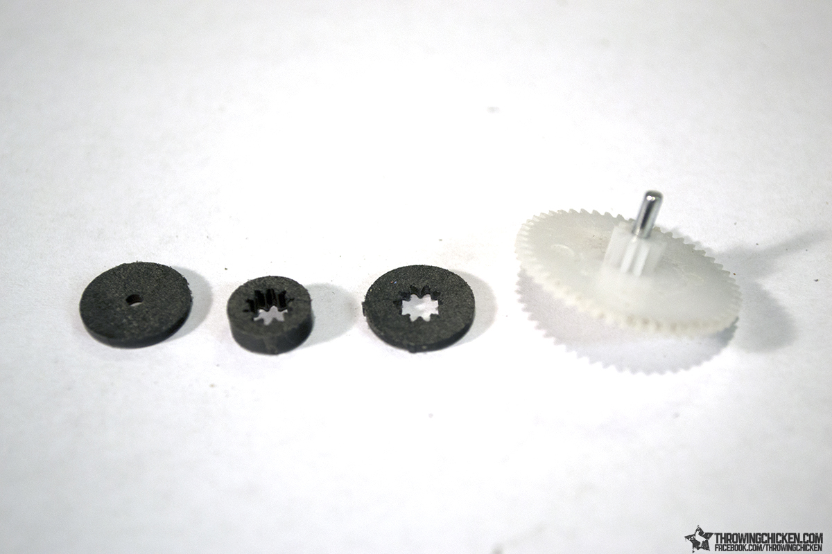
Assembly here is pretty straight forward, it’s just putting the right shape in the right hole in the right order. Start by pushing the axel through the gear.
Next glue down the thin disc with the gear shaped center. Plugs right into place.
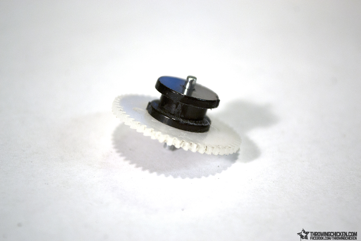
Do the same with the thicker disc with the gear shaped center, and then finally add the thin disc with the 2mm center hole. Everything will line up. You’ve now made a gear with a pulley end for the rubber bands. This is Gear B, set it aside.
Next we will make the second rubber band pulley. This is made out of the two remaining 1/16” thick discs, the 1/8” thick disc with matching hole spacing, the longer axel, and one of the 6-32-3/8” screws.
Start by inserting the axel in one of the 2mm holes along the side of one of the thinner discs, and the screw in the center hole. As with the pulley we made for Gear B, we are going to wedge the 1/8” thick disc between the two thinner discs, bonding them with superglue.
When you are done, push the axel through so that it doesn’t stick out the bottom of the pulley.
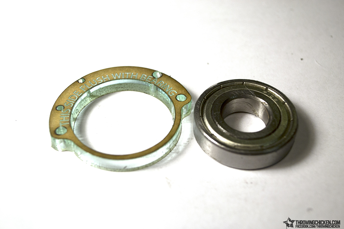
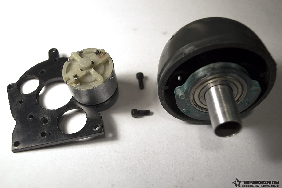
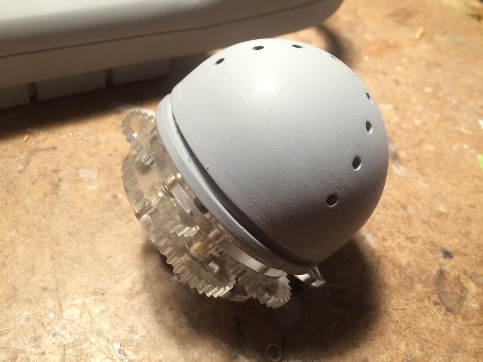
Next up is the dome, but we start here with this bearing. This is a flange-less bearing, but we need something to mount it to the gear head, so we are going to attach our own flange, which is the laser cut piece you see to the left here.
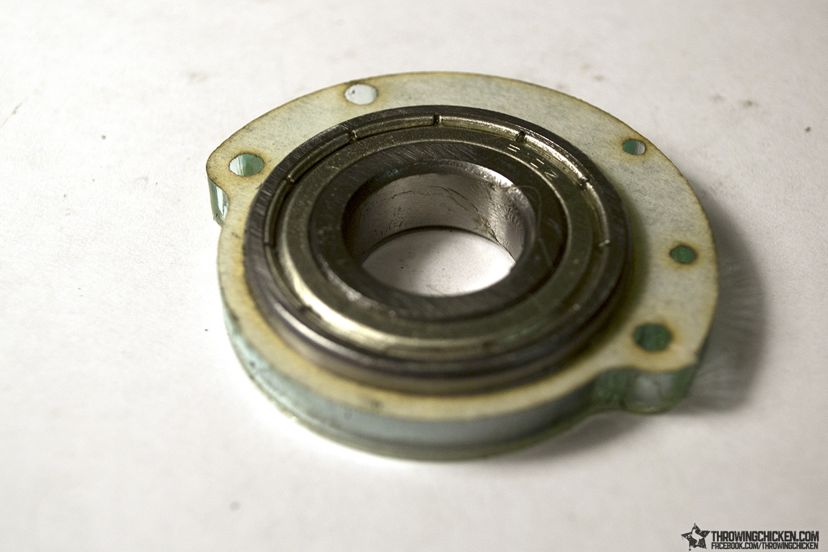
First clear the outside of the bearing of grease then insert it into the flange. Be sure the text on the flange is flat on the table, and flush with the bottom of the bearing. Both bearing and flange should be flat on the table. Trace the outside edge of the bearing with the superglue and let it flow down into the space between. Be careful not to get superglue inside of the bearing!
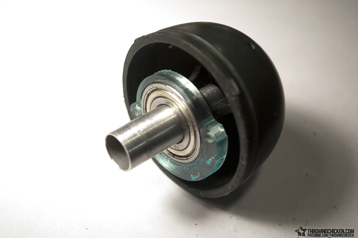
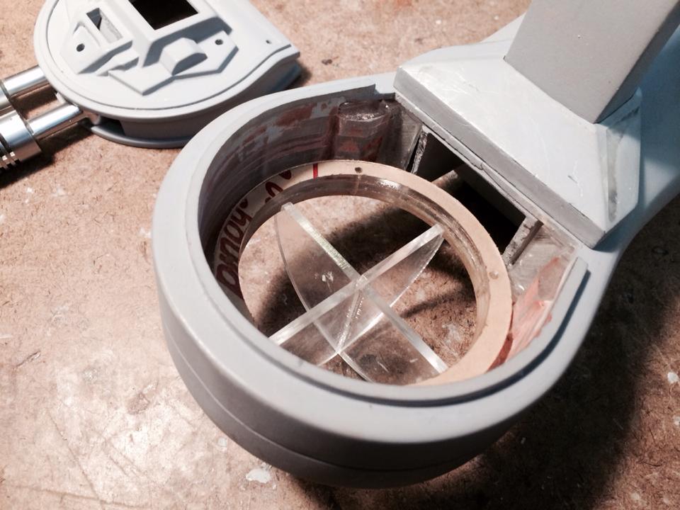
Next insert the aluminum tube inside the cross section on the back of the dome. Make sure it is inserted all the way in before you allow the glue to dry.
Press the bearing over the aluminum tube and push it down until the bearing is resting on the protruding cross section on the dome. Run your glue along the inside edge of the bearing between it and the tube, once again making sure you do not get glue inside of the bearing.
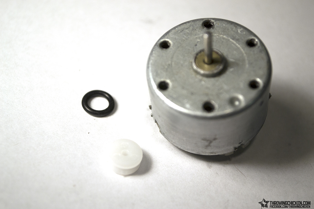
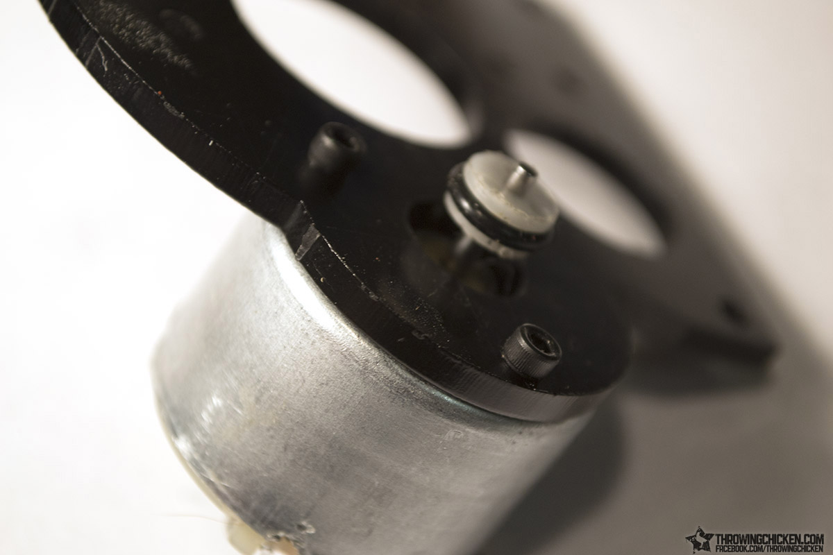
Here are the parts that will attach to the motor (motor not included); the rubber o-ring and the small white pulley. The pulley needs a small modification which can be done easily with the help of our motor and a hobby knife, file, or sandpaper.
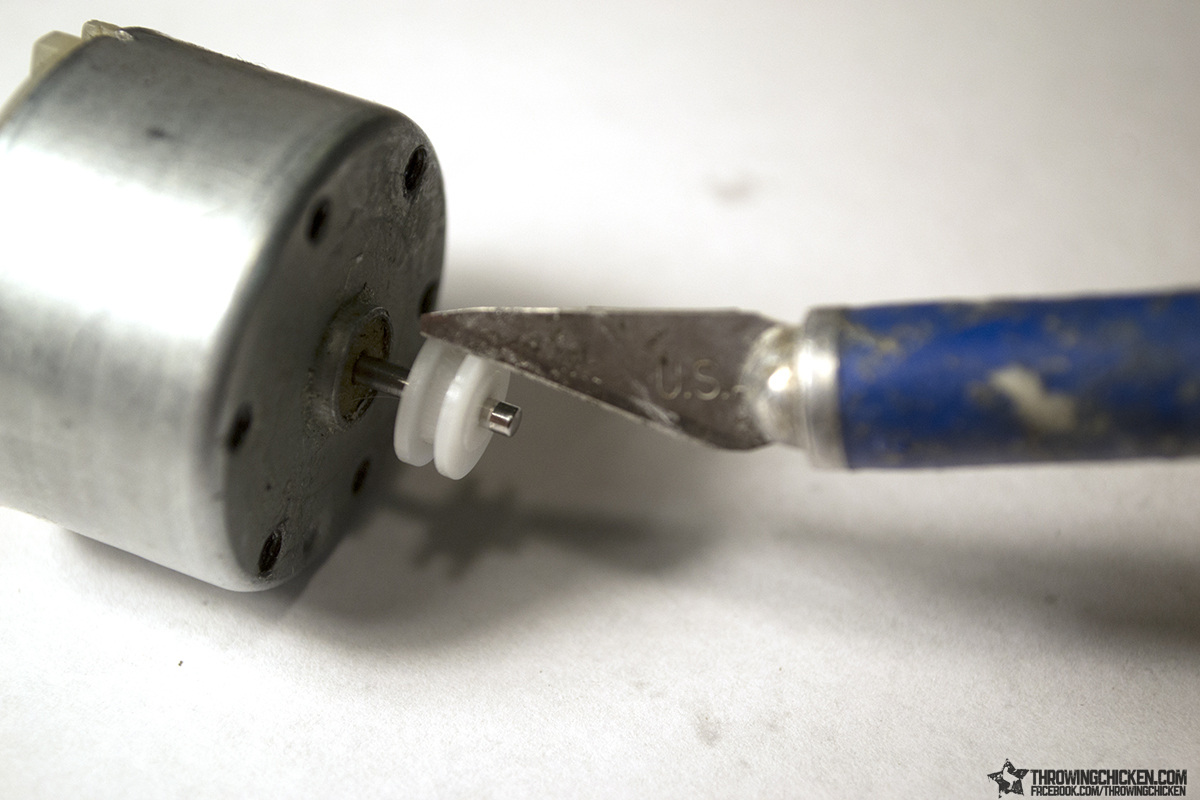
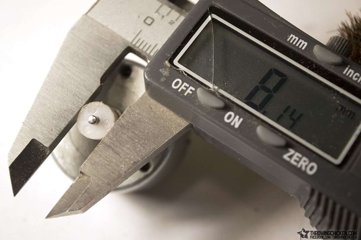
Get your motor up to speed and use the tool of your choosing to reduce the outer diameter of the pulley by about 1mm.
Somewhere around 8.15mm is fine.
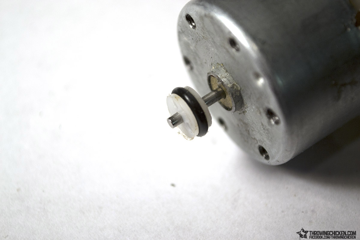
Hey, why don’t you pop on that o-ring?
The motor gets mounted on the right side of the dome mount, with the pulley sticking downwards towards where the dome will be. You have to attach the motor before you attach the dome.
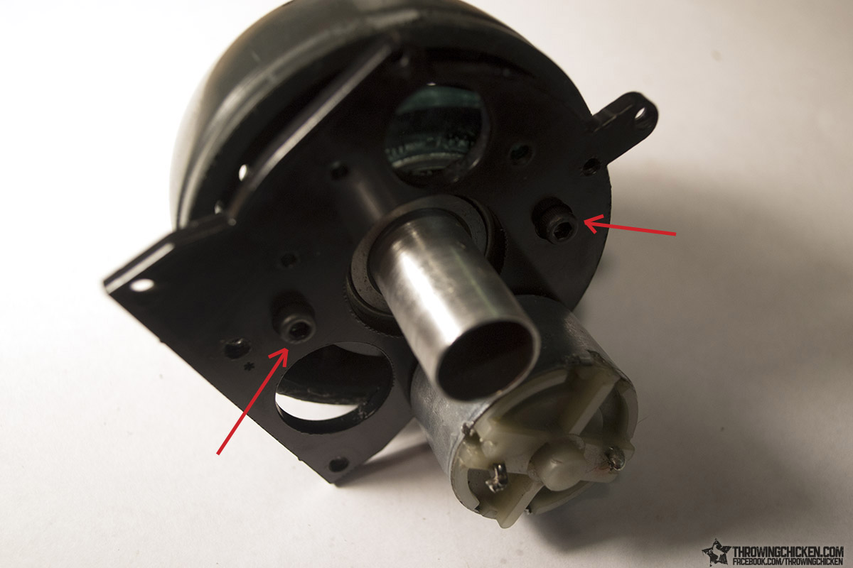
The dome attaches to the mount with two of the 6-32 3/8” screws.
Arrows indicate which holes on the mount align with the holes on the flange. Make sure the thicker side of the flange is aligned away from the motor.
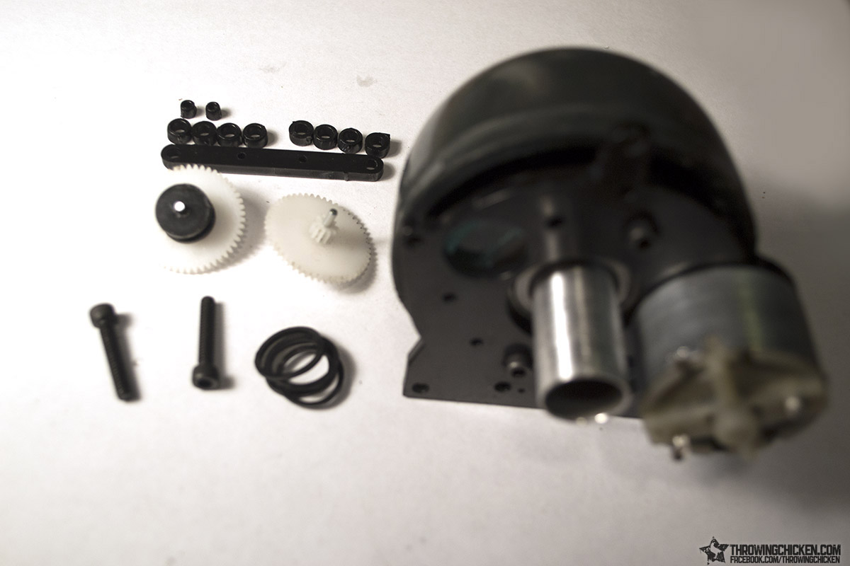
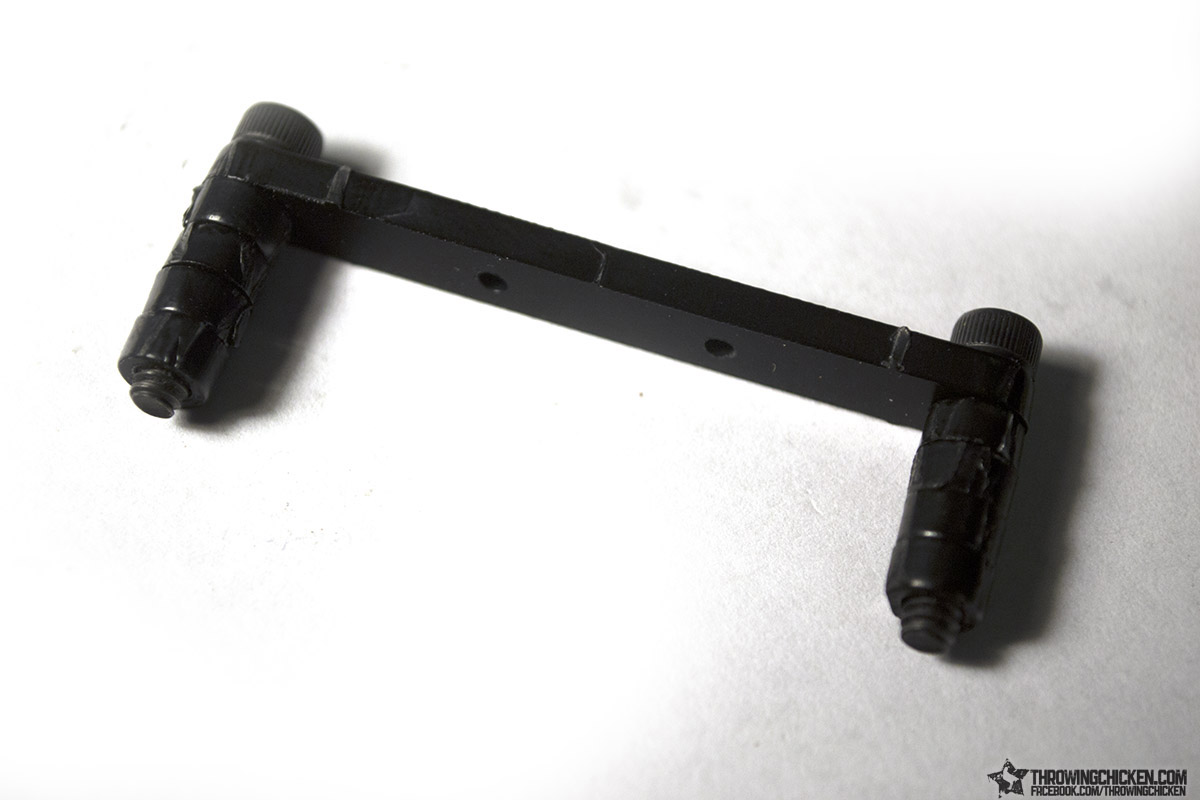
Next gather up a couple of the smaller spacers, 8 total of the ¼” diameter spacers, the gear bridge, Gear A and Gear B, the two 6-32 ¾” screws, and your rubber bands.
Put a small spacer over the axel on the bottom of Gear A (smaller gear side is the bottom side), and a small spacer over the axel on top of Gear B.
Insert the 6-32 ¾” screws through the ends of the gear bridge and add 4 spacers to each side. It doesn’t hurt to glue the stacked spacers together, but it isn’t necessary.
NOTE: Perhaps an oversite on my part, but the Delrin material is maybe a paper thickness thicker than the material I was prototyping on, which isn’t much until you start to layer it together, and in this case we end up with a stack of spacers that are perhaps a hair too tall than intended. I found that they were still usable as is without modification, but it took a lot more fidgeting with the fitting than it did with my prototype material. If you feel like the next few steps require too much fidgeting, you can solve the issue by taking a spacer off of each side and sanding it down a little so that you lower the height of the bridge. Sorry!
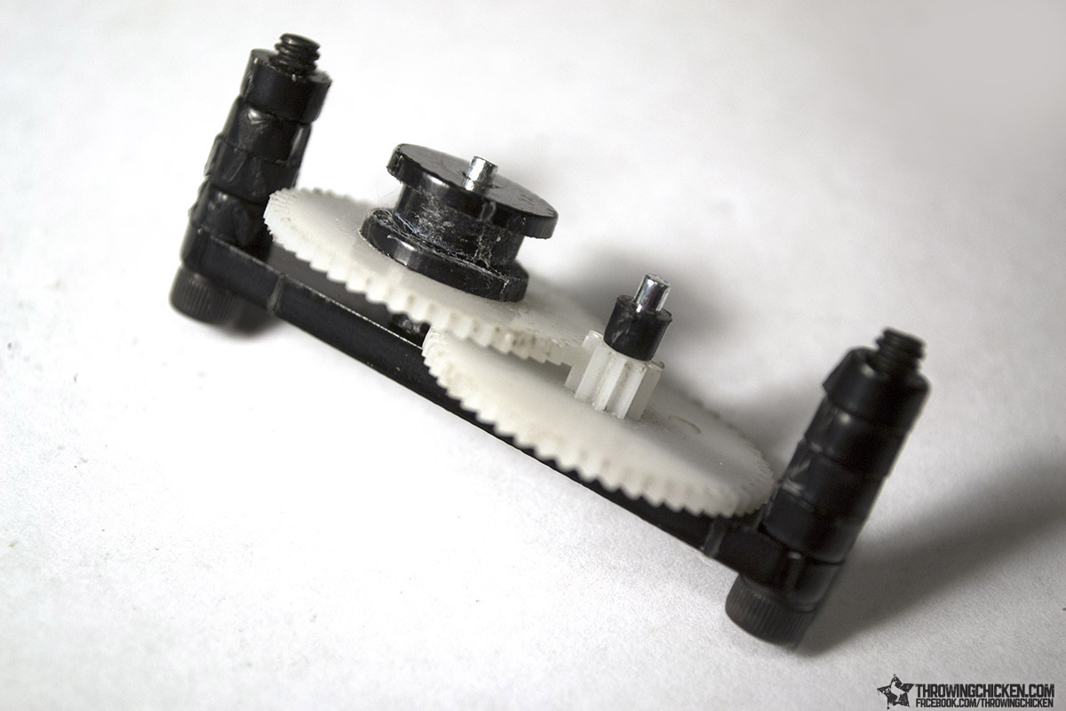
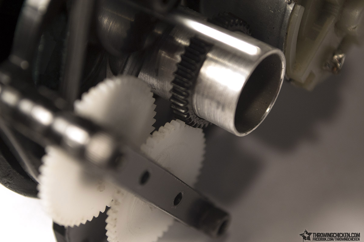
Flip the bridge over and insert Gear A then Gear B into the two holes along the top of the bridge.
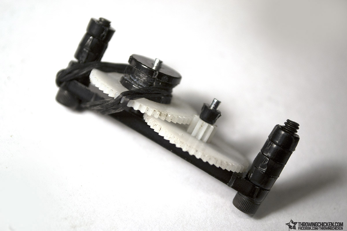
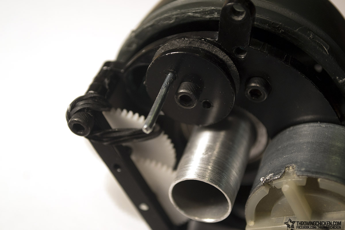
Loop your rubber bands over the pulley on Gear B then hook it over the head of the nearby screw to hold them out of the way.
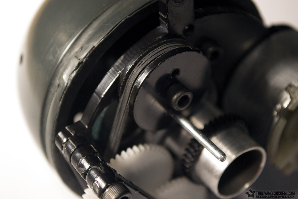
Secure the bridge in place on the mount with the two screws. Use a hobby knife to nudge the small spacers on the gear axels to adjust the wiggle room between the gears and the mount or bridge so the gears won’t bounce up and down when they spin. Once satisfied with your spacer placement, go ahead and screw the larger pulley into place.
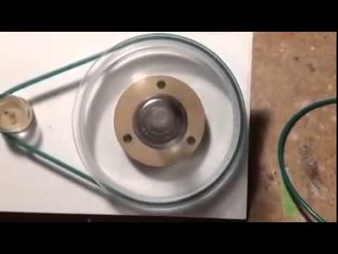
Grab your rubber bands off the screw head and pull them over the second pulley.
If you are curious why we are using a pulley and bands at this step and not another gear, it’s because the axel on this second pulley is actually what drives our ears, and since the ears are likely to be bumped or obstructed, having rubber bands between the ears and the gear system will help prevent binding and potentially broken teeth on the gears.
Locate the laser cut gear with the large inner diameter and slide it over the aluminum tube. Line it up so that Gear A is dead center on this gear, and then glue it in place. Again I remind you, make sure the spacers on the Gear A axel is positioned correctly so the gear isn’t bouncing up and down. If it is then you have a chance of it slipping off the laser cut gear. At this point you can mount the entire dome/gearhead inside the Giga head.
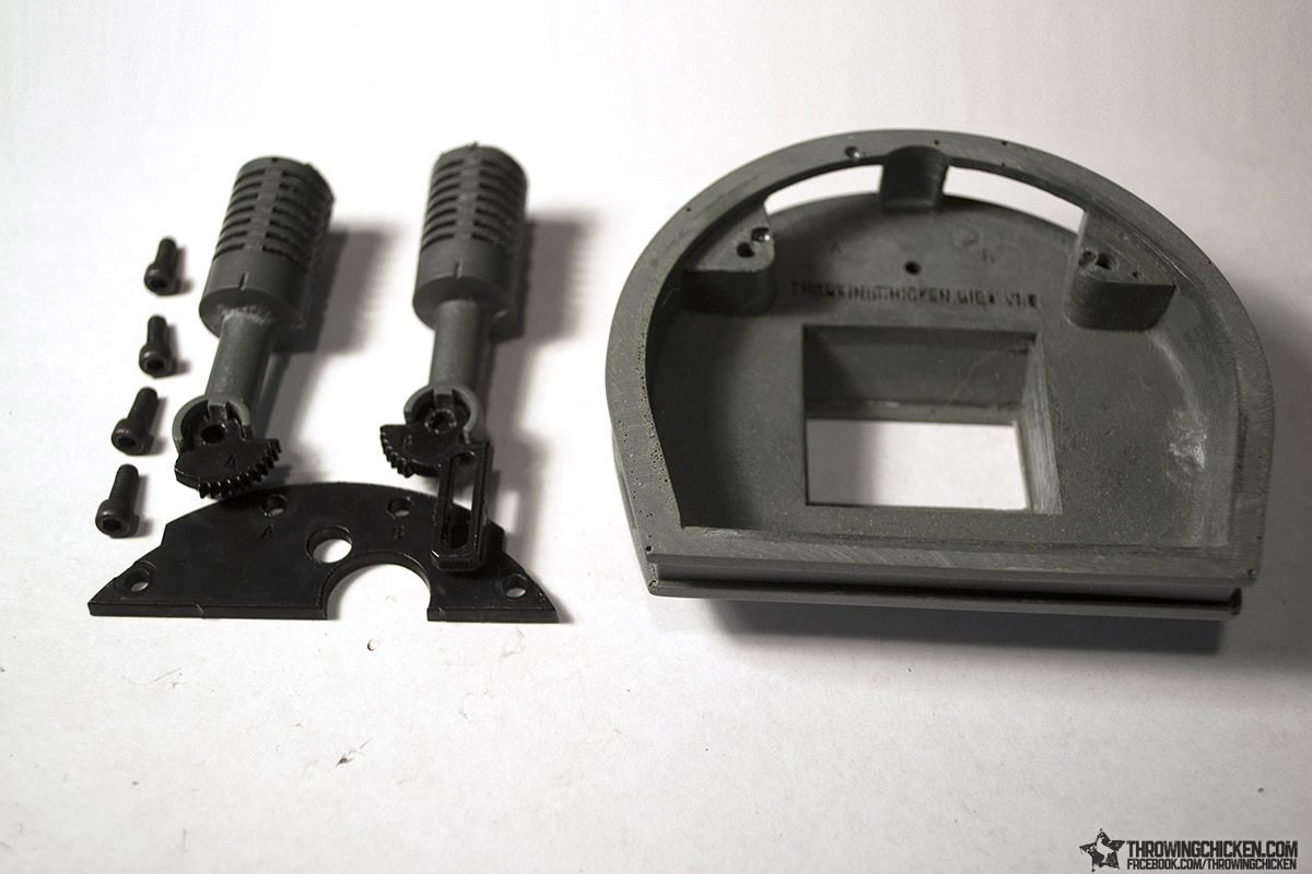
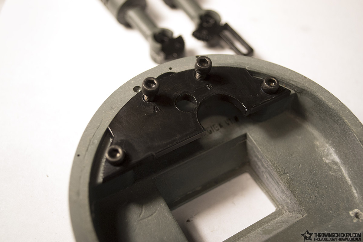
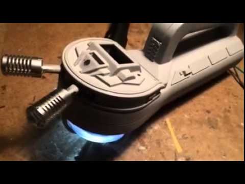
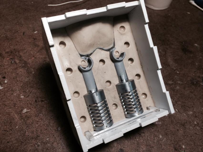
The final portion of the mechanics tutorial is the ears, which goes together fairly simply with the laser cut ear mount, our resin cast ears with the laser cut gears, the four remaining 6-32 3/8” screws, and the instrument panel.
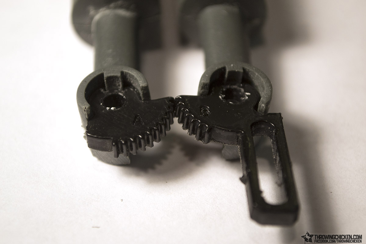
Glue the laser cut gears onto the ears. Match the engraved lettering.
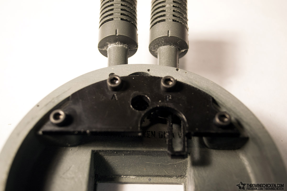
Screw the ear mount into place with the two screws on the end, and partially thread thru the two screws for the ears.
Slide the ears in through the opening on the top edge of the instrument panel and finish threading the screws through the round opening in the gears. You will want to make sure the ears are geared correctly, with ear A having one gear tooth above ear B.
The ears should feel somewhat loose. Even when geared together, they should just kind of flop around (while moving together). If it takes too much force to move the ears back and forth, sand the top edges above where you placed the laser cut gears until they move with little effort.
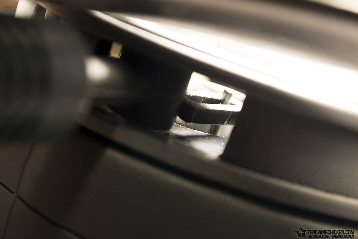
While placing the instrument panel in place over the top of the Giga head, peer in through the opening to make sure the long axel from our pulley is through the slot on ear B.
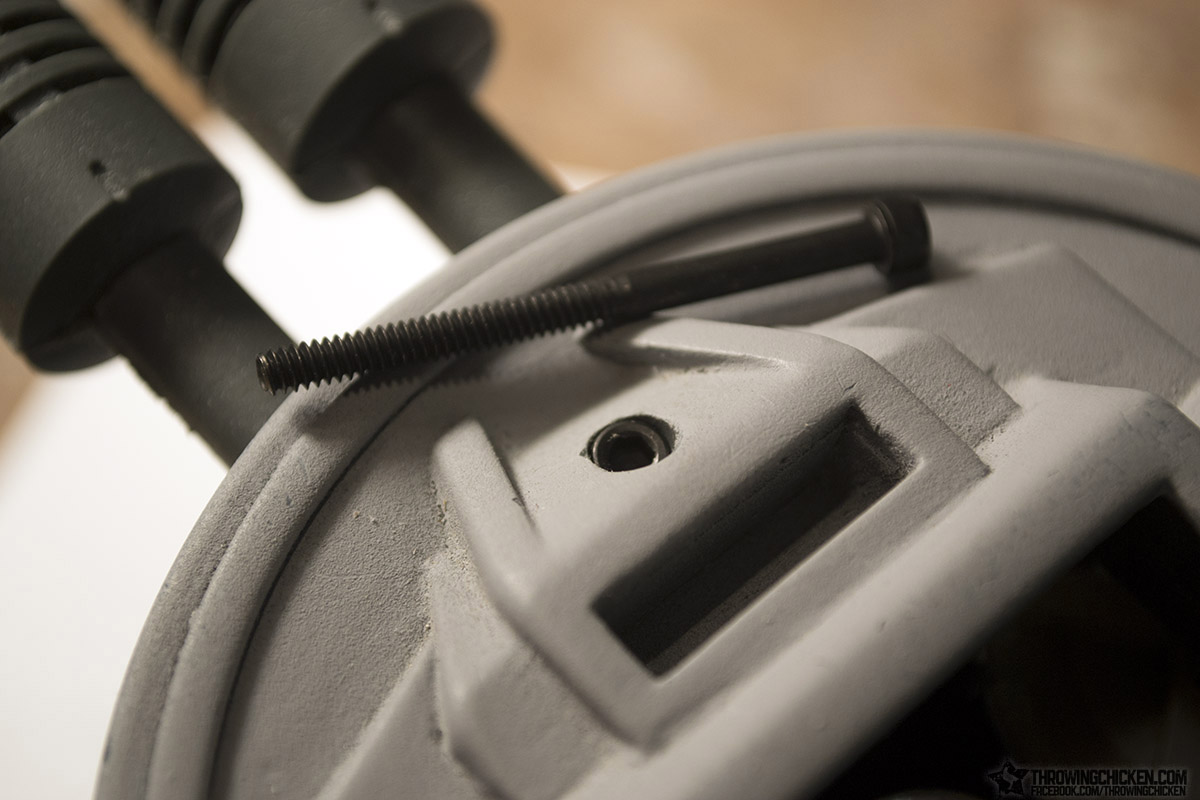
To secure the instrument panel, use the two smaller 4-40 screws along the bottom of the panel, and the longer 4-40 screw at the top of the panel. The longer screw will feed down through this hole here on the dome mount.
Tighten the screw just enough to where the instrument panel isn’t moving around, but don’t go so tight that you start to make the dome mount bow. The two smaller screws along the bottom will do most of the holding.
There you go.
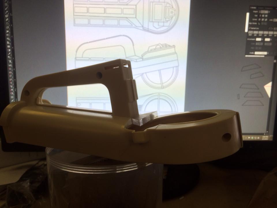
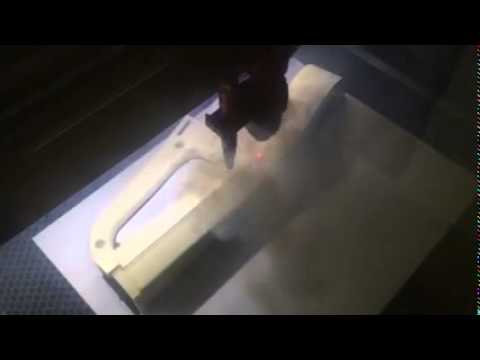
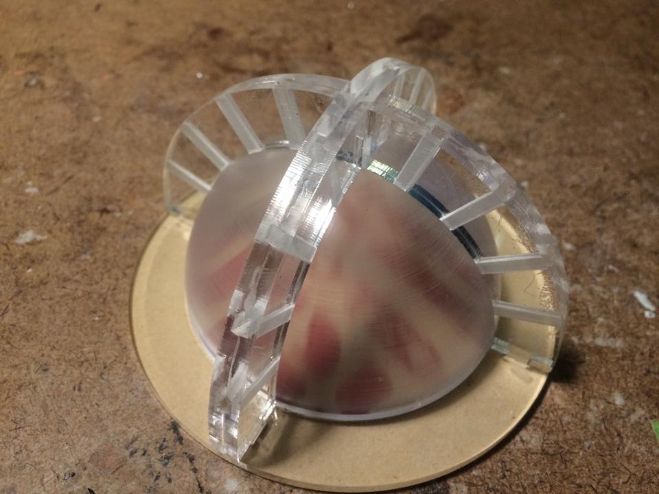
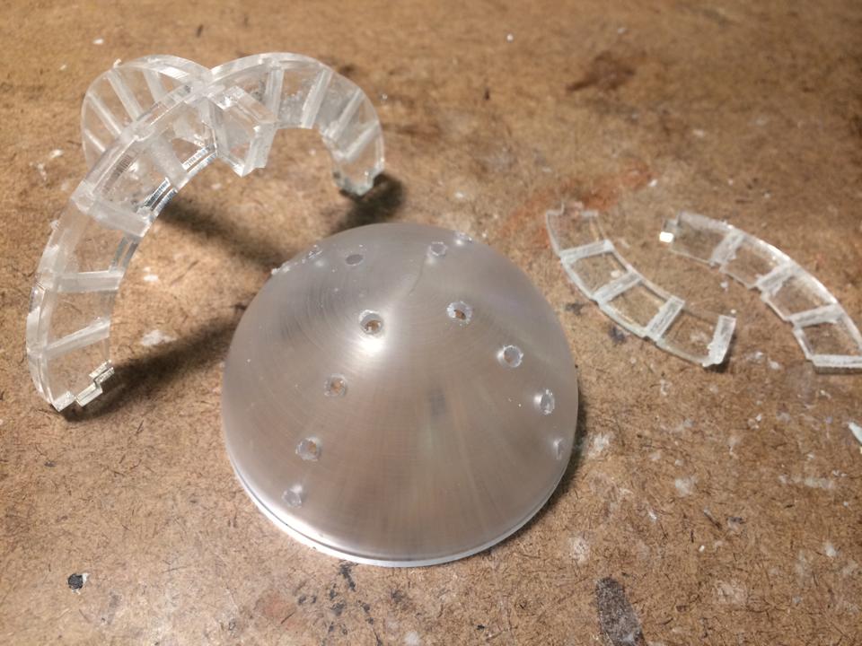
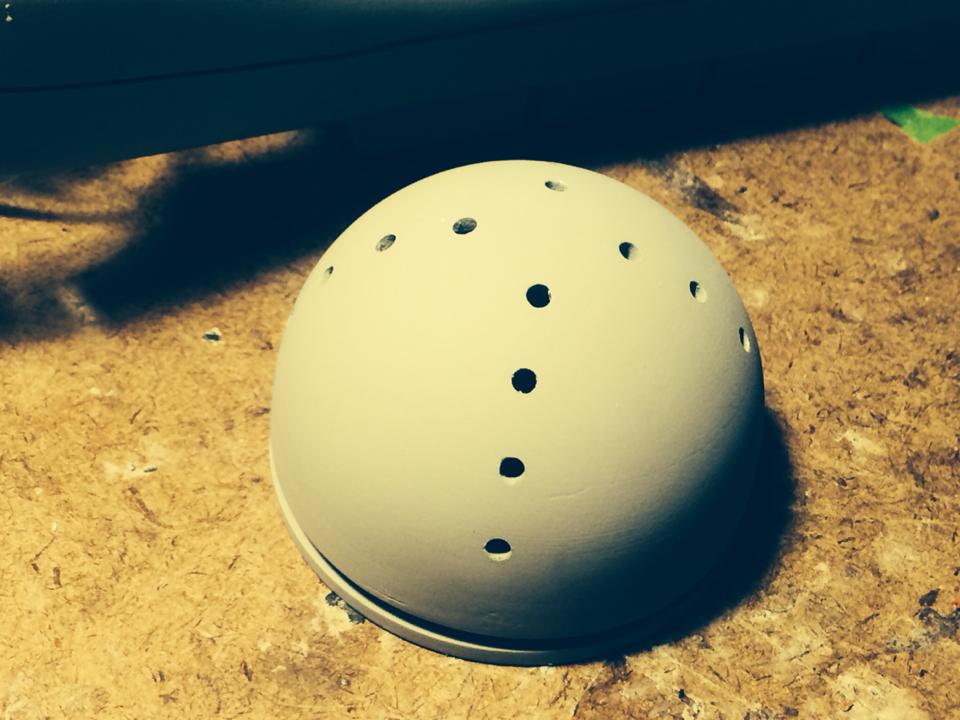
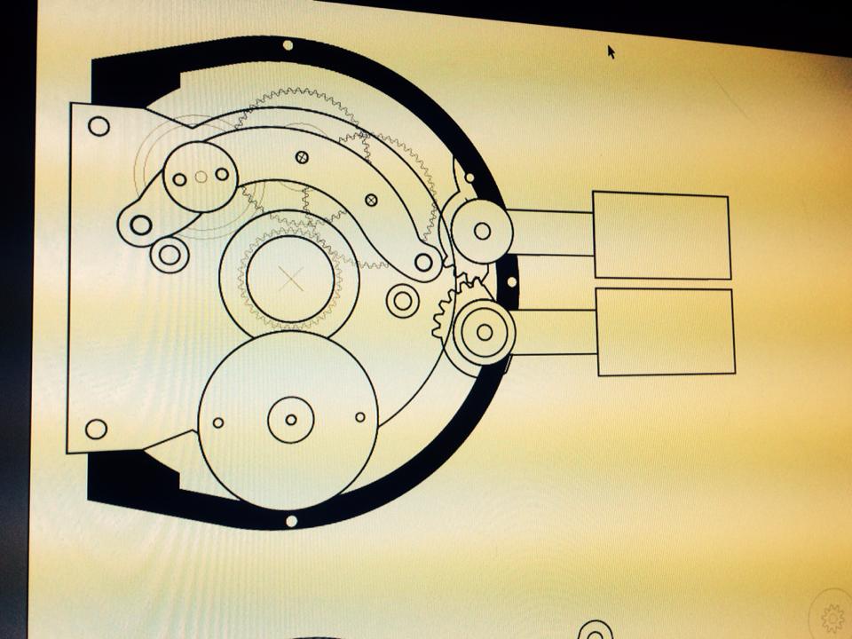


 That approach with the laser was extremely ambitious, I’m glad that on the whole it worked out.