I’d certainly be inclined to dismiss any smaller than expected measurements caused by the Stunt shells. The Venky shells won’t be a help in this field as the valley between the Spacer and EDA is too small to accommodate Beam Line/Filler Tubes which I believe were made to the correct size (the likely result of material loss from the reclaimed mold being cut up).
I’d be inclined to say set it to 1-5/8" as well.
Also, how do we upload to github? I usually don’t use it, and I slapped an early revision of the synchronous generator with 15 spacer segments.
Create a Github account. Fork the project. Add your changes.
Let me know and I can merge the file back into the main repository.
Thanks AJ
Finally got a chance to look over the Gun Mount on my Venky shell a few days ago.
The slant of the gear box side, to the naked eye at any rate, looked pretty similar to the slant on the hook side.
I was looking over the valley in between the synch gen and the EDA/crank. Stefan’s measurements come out to around 1-11/16" square for the corner the beam line sits in. That should leave plenty of room to get the beam line tube and it’s 1-1/2" square base plate in. I haven’t been able to find any decent pictures that show the valley with some form of measurement reference yet.
I’m working to estimate this based on the spacer dimensions. We can also assume for now that the plate on the Hero packs is in fact 1.5" and estimate the offsets on both sides to give us the overall measurement.
I should have some time tonight to mock it up and post some pictures.
Awesome. I’m mocking up some wood real words of the filler right now, so if you can make some measurements, I’ll cut the analogue and see about stuffing some 1-1/2" square bases on it so we can get a good visual.
I really want to finish the Crank Generator (it’s become an obsession)…
I’m getting really close to having something solid I think, but I’m torn between the radius of the edges on the box. Stefan’s plans call out for a 1/8" radius (mostly), but I’ve heard other members mention going even further. I’ve mocked up two models, one with a 1/8" edge and the other with a 1/4" edge…
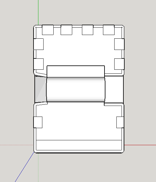

What are everyone’s thoughts as to the correct measurement?
Hey Cole! So cool you are chipping away at this still 
I defiantly think the second option favouring the curves is the way to go, but I think you could even push it a bit more.
Here is a picture of Spenglers hero from front on, I think some of the curves you have laid down need a little work but I really think you are going down the right path
Here is your file overlaid as best as I could.
And here is Just a quick outline I did in illustrator on where I thought the main curve areas were, It’s still missing some bevel lines but you get the idea.
Thanks julz!
I’ll try and get a more accurate view of the model based on that Spengler shot you posted. I’ll stick with the 1/4" radius for now as that looks to be the closest.
Unfortunately, my modeling skills and Sketchup are limited in what I’m able to produce. While I’d love to recreate all of the subtle curves and edges, I’m just not able to do it justice and have spent too long on this one part.
It may be something that gets left to the builder to implement when referencing the plans. I’d for sure look to include a note about it for now until either I or someone else is able to put the right curves in.
1/4" radius edging seems to be the best I think. However, I don’t think we need to worry about making the ribs crooked like seen in the last shot. There seems to be discrepancies between packs, and I think since we’re idealizing them at a 9/16" size to begin with, let’s idealize them as straight (with the exception of the long rib on top of course).
While I’m remiss to refer back to other scratch built packs, I kind of like what chris did on his crank gen with the vac line recess. It has a curved step that gradually blends into the gun mount spacer. I need to pull up pictures of shells that have lineage to see if they handle that area the same.
And not to get ahead of ourselves, I was looking at the width of the filler between the crank and the gun mount. It looks to be roughly 1", and with my wooden mockups, having the 1" in between lines up the corner plate and the gun mount properly.
I’m inclined to think that all the hero’s had the exact same shell which included the same fins and their placement
All the crooked alignments seem to match up from pack to pack.
I would be happy to have a go at that area myself Cole… but I model in maya so I’m not sure if I can convert or I would need to learn how to model in solid works :walterpeck:
For the most part, everything’s been exported to STL.
Sweet, I’ll have a crack at it then, as I can defiantly write out to that format.
I can export OBJ files as well if that would help.
What is meant by “crooked” fins? Are we talking about the mis-aligned fin on the left of the top box, or the bottom fins that don’t have equal spacing?
The real question is whether we include these in the plans or not. We already have mis-alighted fins on the side of the Powercell and top of the Crank Generator, but these are much more noticeable than say the crooked fin on the left of the Crank.
I would think the bottom fin detail would be included in the plans. I’m not sure what I think about the “crooked” fin seeing as how it’s shown on every pack.
Thoughts?
For what it’s worth, I tried to take as “face on” a shot of the Gear Box from the Venky shell:
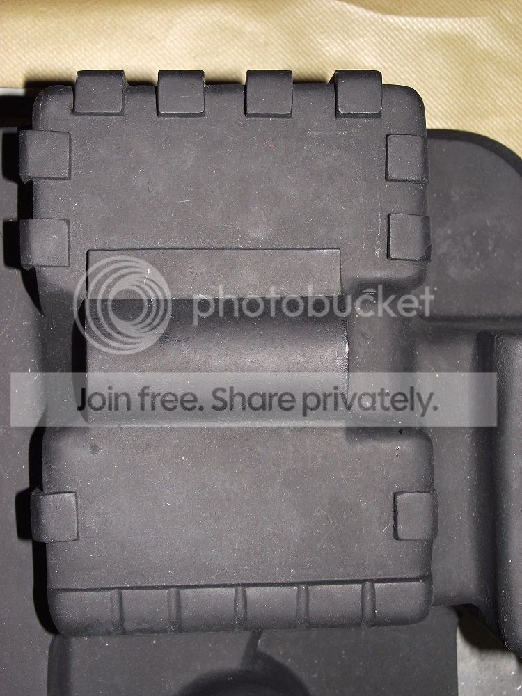
-funny how I never noticed the kink in fin on the left side of the Gear Box until it was pointed out. 
Here’s a couple to throw on the pile for the Gun Mount:
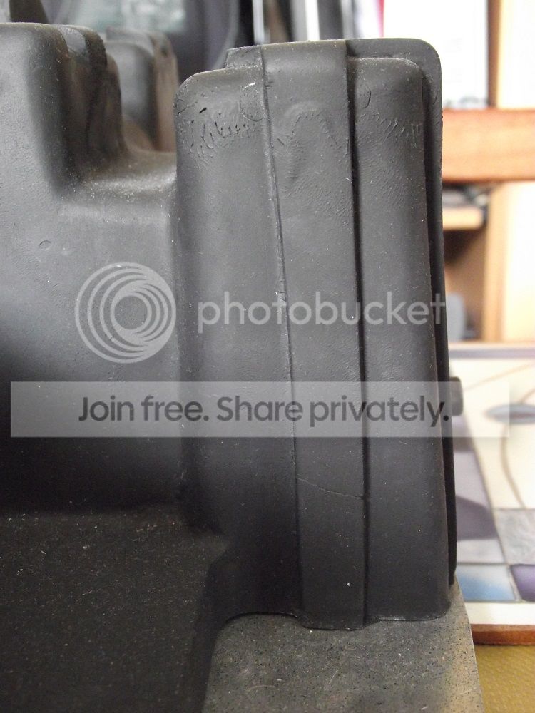
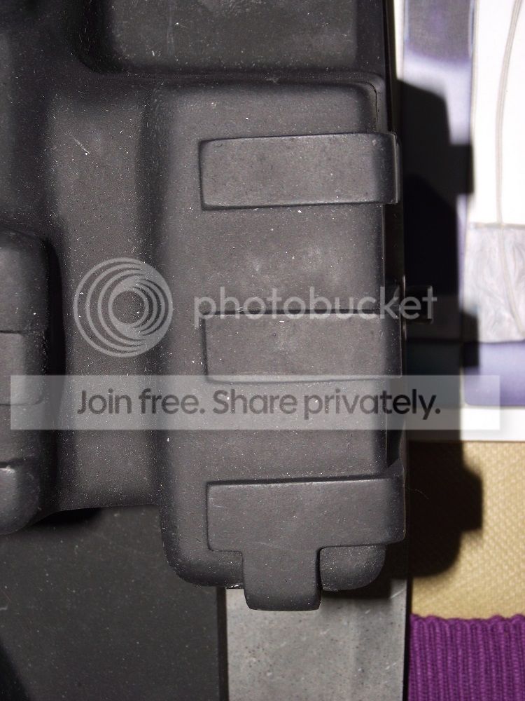
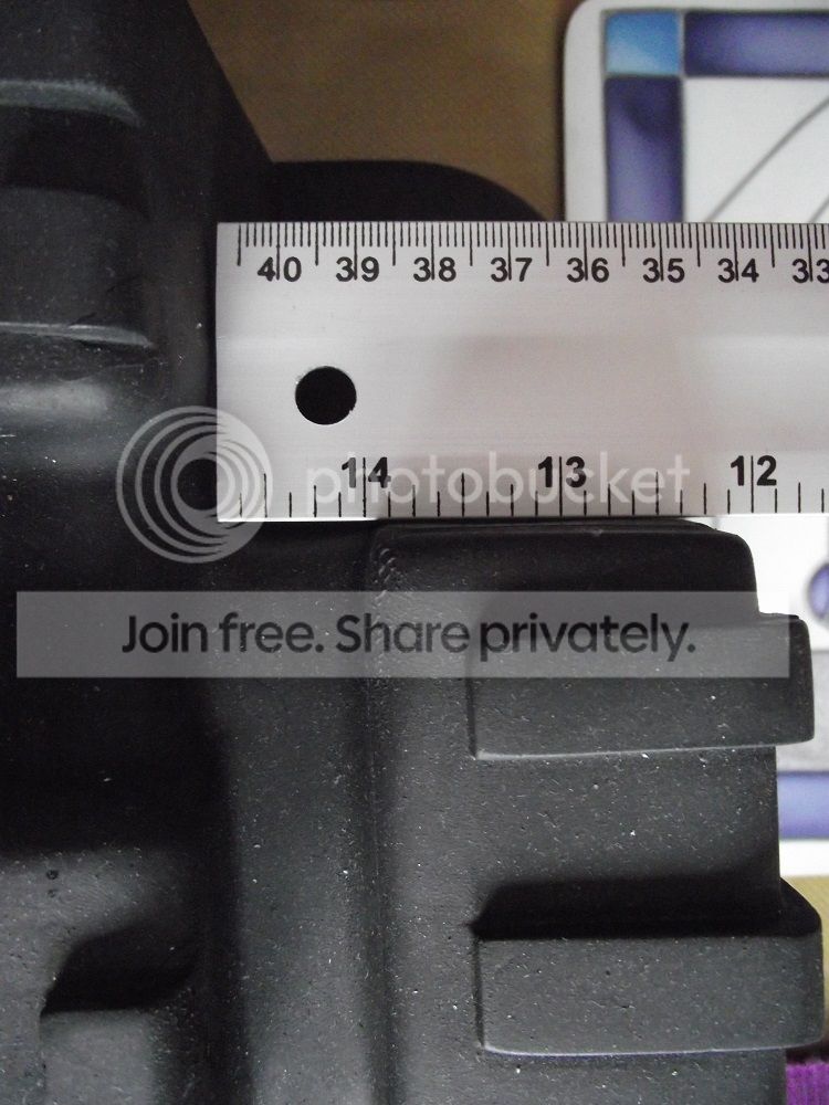
There is a lot of distortion on the picture caused by the camera lens. Try to do that straight on shot from a further distance away (possibly zoom in) and it would be better. Or if you know what kind of lens it has, I believe it could be corrected out through photoshop.
So the gun mount looks like it was a box that was given a slight lean from that picture. Could that be the nature of the mold that venky pulled his shells from? If we stick with Cole’s tapered plans for all 4 faces, that should allow a 3/4" filler like what I see that will still line up with the corner plate.
As for the crooked ribs on the face of the crank, I say try and position them the same, but we’re already sacrificing some accuracy on the rib size and spacing for the sake of uniformity. We could always just leave it to the individual builder if they’d rather idealize the ribs or stick with the more accurate positioning.