I was going through the forum earlier, and a noob asked how to make a pack.
The answer was that Stephan’s plans weren’t totally accurate, but a good place to make a pack nobody else would know was inaccurate, so I got to thinking;
It’s been a while since Stephan’s plans were considered canon, and I’ve sought approval to update the plans to remove the known discrepancies, and create the GBFANS plans, which can be updated as needs dictate.
It would be my proposal to go through Stephan’s plans one sheet at a time, and create 1:1 drawings that can be used to build your own pack, or mounted on foam board as some really cool wall art.
The logical place to start would be the motherboard, which is sheet 1, and work our way through.
I think we could get through this in 3 to 4 weeks if the input was solid, and I’ll get AJ to make a new plans section for the community effort.
Using the Mobo as a rough template would be a ok idea. That being said, there will be adjustments made to the parts that would make the mobo sheet inaccurate and in need of change. It might be easier to start somewhere else and give it a go.
Seriously though, a new set of plans based on what we now know is something that’s been long overdue… I’m definitely looking forward to seeing how things develop and materialise.
I’ve been playing around with this on my own as I needed some reference for the powercell. I’ve been using Sketchup as I can pull dimensions off of the model very easily when I need to. Here’s an older picture of what I’ve been working on:
I’m not sure how you’d plan on having other people involved or what software you’d be using but I’d be more than willing to supply time to this if you need it.
Viewing the Power Cell elevations raises the question, are we going for an idealised look, or prop accuracy?
If it’s the former, then I suppose the straightened fins are acceptable, but if it’s the latter then the fins would require modification to include the slanting on the side of the Power Cell, and the thicker end where the lowest fin meets the Mother Board.
Dave, what program are you using to produce the Elevation and Isometric views? It AutoCAD?
Are you just copying Stefan’s plans into a new file and asking for corrections to be made?
It might help if you put in some of the corrections from the beginning to limit the number of needed. The reference section has several pictures of the power cell alone with a tape measure next to it in case you weren’t aware. That’s what I’ve been doing while modeling my parts.
Kingpin does raise a good question about what type of plans we’re making. I would prefer plans based on the real life packs while I’m sure others would prefer an idealized pack as mentioned.
I would also like to know how you are approaching this. Are these just 1x1 off stefan’s plans and then you are asking for updates? Or are you adding the updates you can find before posting?
Depending on which way you are going will influence how I can help and what to focus on
I’d like to see stuff as accurate as possible with drawings, and 3D files available.
The 3d Files should be made in a way that would allow them to be opened, edited and re-uploaded by anyone to make improvements. (Solidworks files are probably going to be the best for that). We’ll have to start a section in the Wiki for them, and I’ll have to make prt, and sldprt files accepted as upload types.
Happy to help myself… Model wise or just feedback.
My personal preference for gbFans site plans would be for accurate plans as close to all the random details the hero’s had.
Hey Cole I think you need a thicker base for the lowest fin…the far side of the powercell tapers in towards the front. The bottom fin almost looks like a wing instead of a straight line…
I’ll have to upload another picture of my model to show but I think it’s just the perspective of that shot or the age of the model. The bottom part of the fin on my model sticks out far enough so that the injector tube plate and the part I’ll call the powercell/injector spacer (I think about 3/16" thick) sit flush at the bottom of the powercell as shown in this picture:
I’ve never used Solidworks but I’d love a chance to learn it and contribute in any way possible.
Obviously details that are warped or broken will need to fixed up and not presented in the plans. Things such as the fin spacing on the powercell, crankbox, and gun mount, while not perfect, should be modeled and presented as they actually are in my opinion.
If a person were to decide to “idealize” their pack, it is much easier to space the fins out evenly on their own than try and figure out the actual uneven spacing the screen used packs have.
Again, this is all my personal preference and it may differ from everyone else. I sort of see Stefan’s plans as an idealized pack already and these plans would be created to reflect the actual unbiased dimensions of the props.


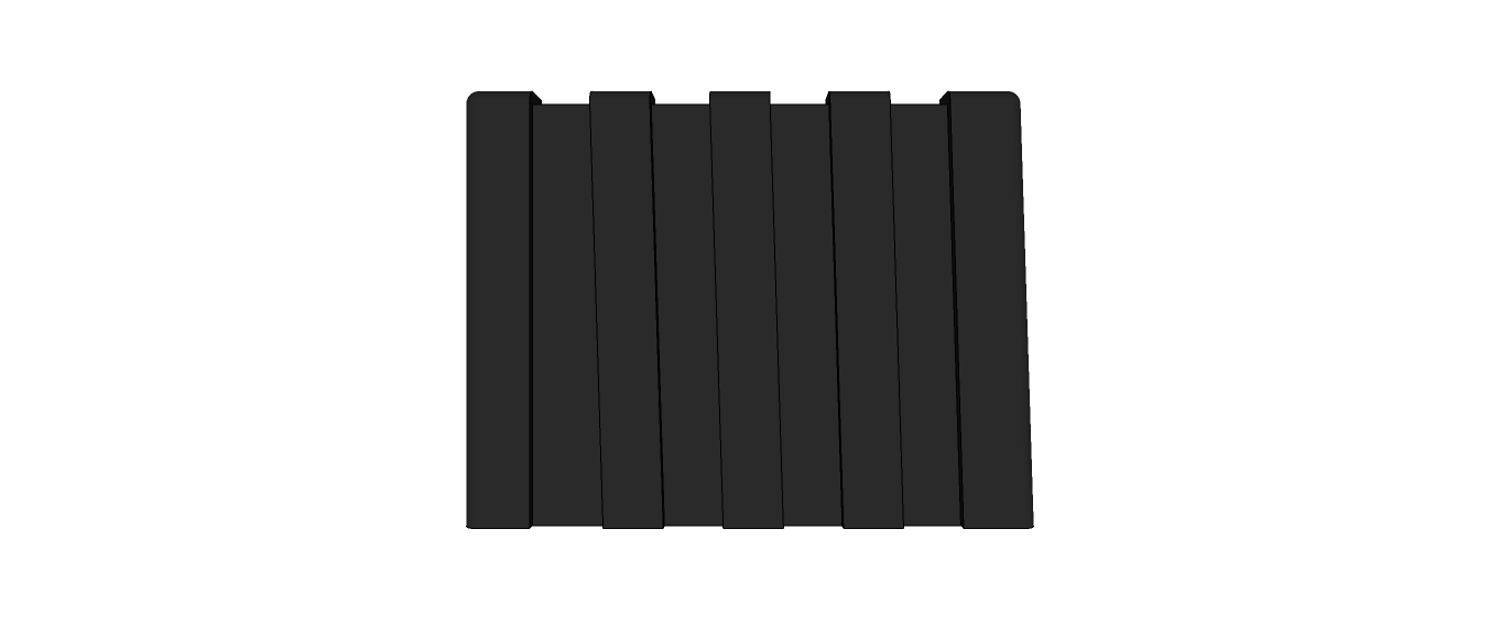

 I think you need a thicker base for the lowest fin…the far side of the powercell tapers in towards the front. The bottom fin almost looks like a wing instead of a straight line…