Personally I would vote for screen accuracy. I think that’s what most people want. It’s what I want. If there were enough demand for an “Idealized” pack I guess you could make another set of plans? But the problem with “Idealized” is who is to say what is “Idealized”? The nice thing about screen accuracy is that it isn’t subjective. And honestly if you wanted an “Idealized” pack then Stefan’s are pretty damn close already.
I agree that Stefans plans are close enough as far as idealized is concerned. The only thing not idealized about Stefans plans is the taper on the crank generator.
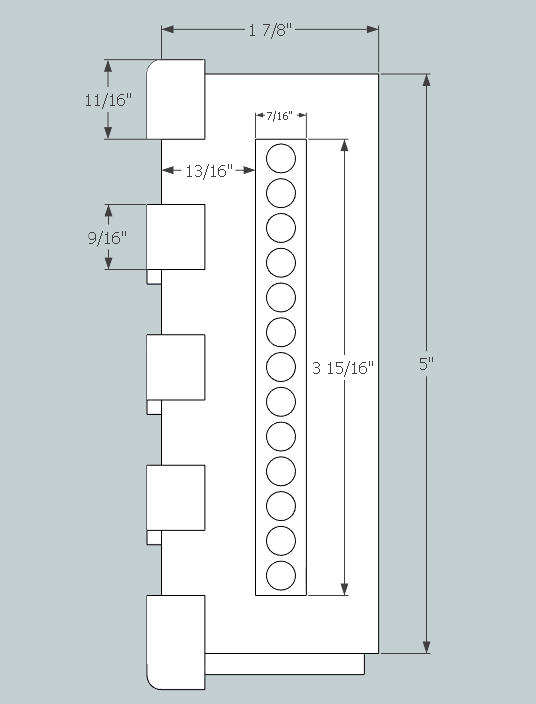
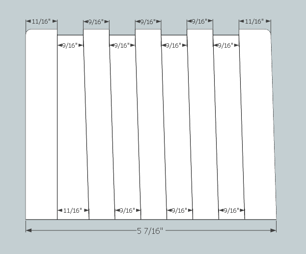
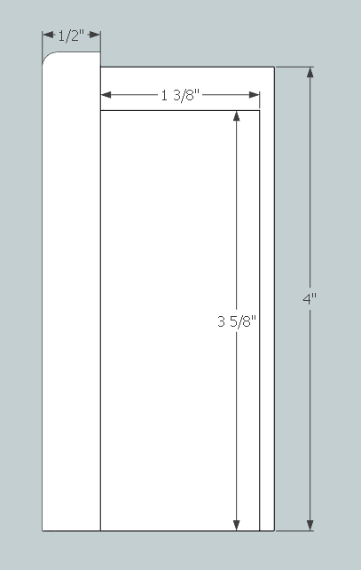
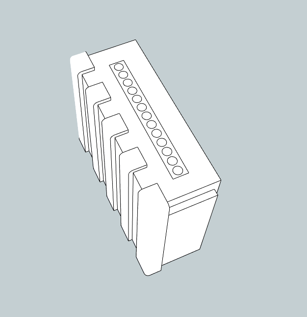
Here are the dimensions I’ve been using. Not sure how best to mark up your PDF so I figured I would just post these instead:
Top:
Side:
Bottom:
Overall:
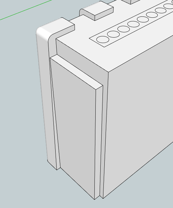
julz: Here is how the bottom fin looks from a direct angle. You can see that even with the 3/16" plate on the model, it still sticks out roughly 1/8".
Let’s get this thing going!
Nice models Cole  good work!
What I was referring to was from above or below the powercell the front of the powercell is shorter in width than the rear of the powercell where it meets the pack. so looking up from the bottom all the fins actually start of thicker and wedge down to the front sort of like a triangle or wing.
1 Like
Excellent model, and those photos are great.
I’ll have something based on this input later today.
I had seen that before but came to the conclusion that the power cell and fins didn’t taper like that on the GB1 Heros. If you look at the Sony Hero, it does not give the impression that the power cell or the fins have a taper:
If you compare the top of the fin there to the bottom there isn’t much difference as opposed to what your pictures showed.
I assume the pictures you posted were of the Venky shell? I’d be hesitant to use that as reference for this as I thought it was originally a stunt pack that has been overhauled and casted several times (or so I’ve read).
What are your guy’s thoughts? I’ve been looking at pictures too much to know anymore.
I can see the taper in those pictures you just posted
It might seem a little or a bit more subtle but it’s still there to my eye. The rear of the fin is defiantly fatter…
Fight fight fight fight 
It’s a Chris shell by the way, he was pretty ■■■■ about all his measurements
1 Like
Ha, no fight! Just wanted to be sure as I hadn’t seen it like you guys have.
About how much does it taper out at the bottom? 1/8" maybe or more?
I’ll let you know tonight, I shall get out me ruller , also I’ll have a lookie over the sony studio pics, there is a neat top down shot of murrarys pack so Hopefully that will provide more insight
If you look at this image, you can see the Power cell does taper, but the thickness of the rib is constant.
Can we agree with the angle of the ribs on Cole’s drawings, and that the taper is due to the shape of the box, and not a varying thickness thickness of the ribs?
Also, the injectors sit on a second plate under the standoff/platform that is already indicated in Stefan’s plans.
Here is the power cell blueprint based on today’s discussions.
I have tapered the unit from the top and left sides, and offset the bottom rib to taper up 1/8" at the front.
I kept the original dimensions at the back, so it is compatible with the existing MOBO.
The right side and bottom would appear to be perpendicular in those photos.
If we can agree on final aesthetics, I’ll add the second bottom plate with the injectors attached,.
Cheers,
Dave
Sorry for flooding this thread with more and more pictures!
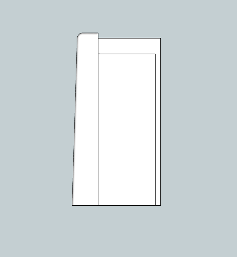
I plugged in an extra 1/8" at the base of the powercell and re-modeled it to see how it would look:
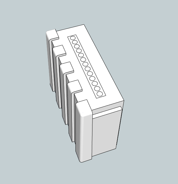
Looks good to me! +1 for julz and the rest of the gang!
Ramjet: I see a couple issues with the blueprint you posted.
First is that I do not believe that the main powercell box tapers on the top or bottom. Only the bottom four fins have this angle. If you look at a profile view of my powercell, it shows up like this:


You can also see here that the top fin is at a 90 degree angle with the motherboard while the bottom four are at an angle. When I look at reference pictures of the hero packs it looks like how I’ve modeled it. What are your thoughts?
Last is that the top fin is missing the top section. Just needs to get filled in I believe. 
Again, all of this is based on what I have modeled and may be different than what others think. Julz seems to be the only other one in this thread so we’ll have to see what he’s thinking.
Thanks for pointing that out, Cole. I didn’t cap the top and bottom ribs.
My reasoning for the taper at the top is that this was originally pulled from a mold, and would have had to be tapered on at least one side, and either the top/bottom.
Given that the injectors are perpendicular to the bottom, I put the taper at the top, but can leave it off for the next revision.

Looks good both of you, I really like what you came up with Cole. It’s a subtle tapper and from some angles it looks like there isn’t one at all.
Here are the pictures I sent Cole before, Probably best to put them in here as well…
The bottom one is a stunt pack which I’m fairly sure is cast of Murrary’s pack… I’ll see if I can find more ref, and I am happy to put in the measurements I came up with for the hero nfilter with accurate murrary holes.
The top fin looks a bit different as well, the space between the rest of the pack and the fin is filled in.
I’m not sure how people feel, but I would personally like the plate under the powercell to be separate, but added next to the plans. Or a couple of version where you can see it with out and the plate next to it and with it combined. The mold didn’t have the plate included so if we are striving for accurate plans…
1 Like
I think just adding it alongside the powercell with the injectors would be fine. It’s obviously there in the hero packs whether or not it was cast into the shell.

Submitted for discussion.
Thanks, Julz - once we marry this part to the pack, I’ll fill in that piece on the top rib.
What parts of Stephan’s plans are considered accurate - Booster Frame? Bumper? Ion Arm?
If I can get the parts that are already considered accurate drafted, we can spend more time on the ones needing a little interpretation.
Dave.
This is a long overdue project! While it won’t be helping me on my current build (I’ve finally jumped back into pack-building after my last effort went awry) it’ll be nice to have these plans when I inevitably start my next one.
While it would certainly make things easier, it wouldn’t need to be tapered for demolding; the shell would have been cast from a flexible mold. The angle of the ribbing alone creates an undercut.
The general rule of thumb is: cast hard from soft and soft from hard.
Looks great… both you and Cole
I would move onto the infamous crank gen box and gun mount
those plans are so out of date and there are all sorts of curves that need to be added to that thing that the old plans don’t have
If you could point me to a thread to get me started on documenting the required changes, I’ll get cracking after the weekend.
I’ll be away for the next few days.