Have a look through that thread. In my mind it’s the most accurate shell i’ve seen and it has a nice step by step process…
That’s also the shell I have
Have a look through that thread. In my mind it’s the most accurate shell i’ve seen and it has a nice step by step process…
That’s also the shell I have
Nice work on the Power Cell guys.  I’ll take a look through the Sony Lobby photos at some point just to compare, but the newest version of the drawing is looking pretty spot on from my admittedly foggy memory.
So I was trying to look at a few measurements and I’m having a hard time.
Other than that I think they it looks pretty good. I am at work so I’ll take a look more closely tonight and let you know if I have any other questions/comments.
If you take the angle of the photo into account, it looks to be just about 1/2". With the fins being 1/8" thick, this means the fin hangs over the powercell face by 3/8".
On the bottom I see it being about 5-7/6" and the top being 5-5/16" equating to a 1/8" difference between the two. This is how my model works out and should be how Ramjet’s works out as well.
I’m thinking in the photo the ribs are just a touch more than 3/8" … probably 7/16" … but I it’s really up for debate.
The Top I think would fall more along 5 1/4" or even just under. While the base is probably closer to 5 1/2" IMO. If you would draw a straight line from the base to the tape measure it’s probably the 5 7/16", but if the tape measure was at the bottom (of the other side…top of picture) it would add to it since it’s tapered.
Also I wasn’t so much questioning the photo’s measurements as I was the plans since there aren’t measurements listed on them. I should have clarified that better.
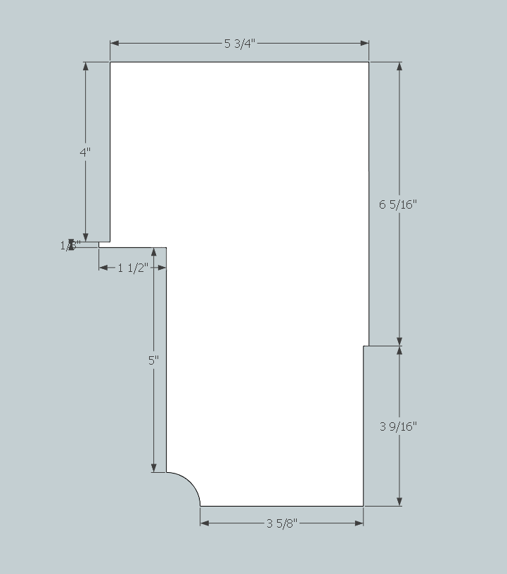
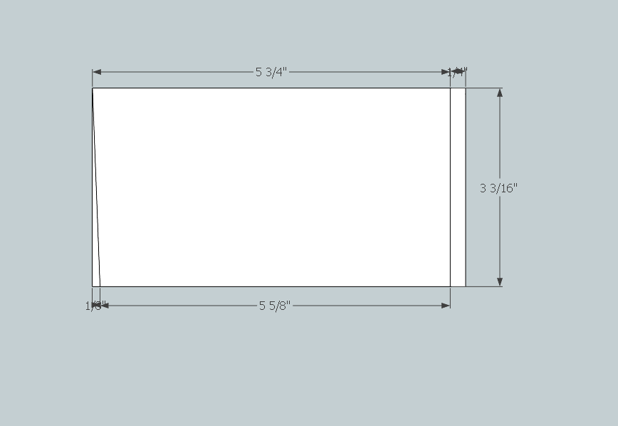
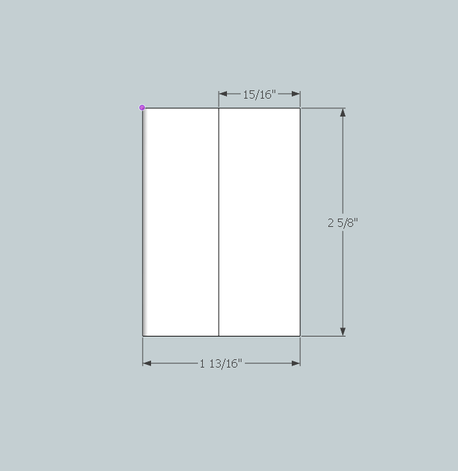
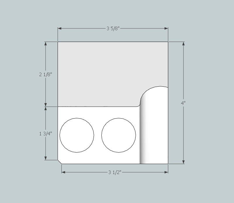
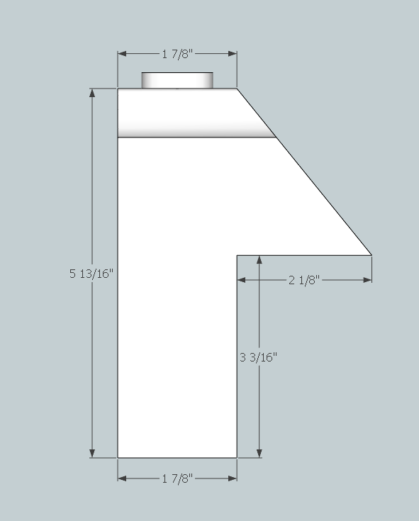
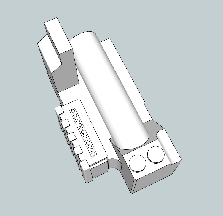
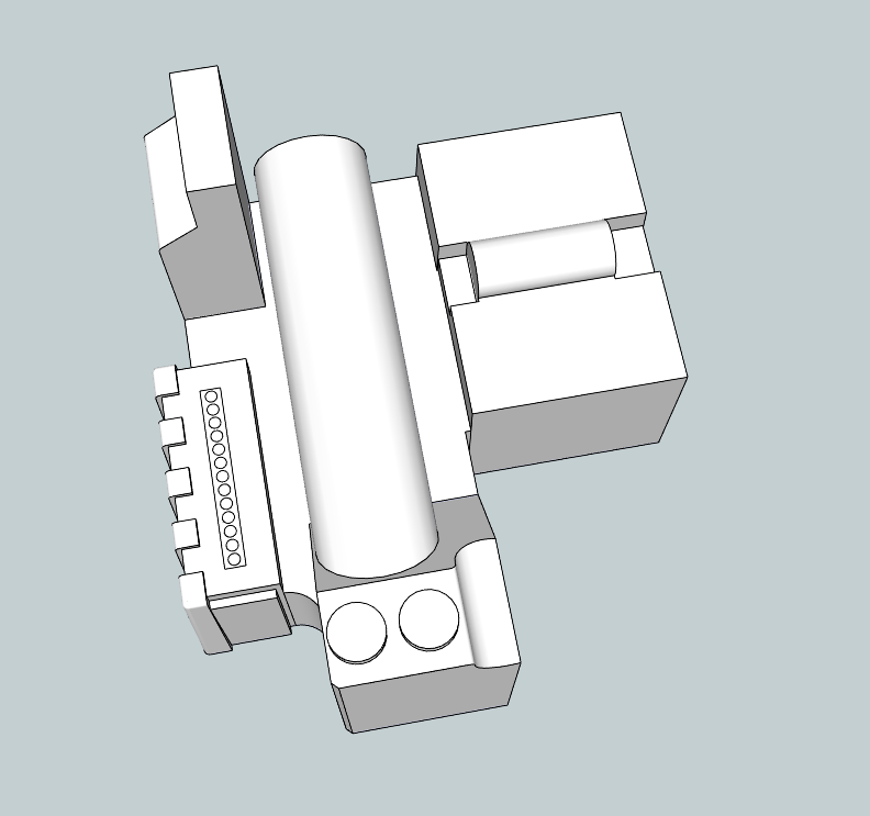
I’ve been working on the model a bit more as I don’t want this project to slow down. Some of these are very similar to Stefan’s plans with only minor changes based on what I’ve seen from the photos:
EDA:
PPD:
Overall Progress:
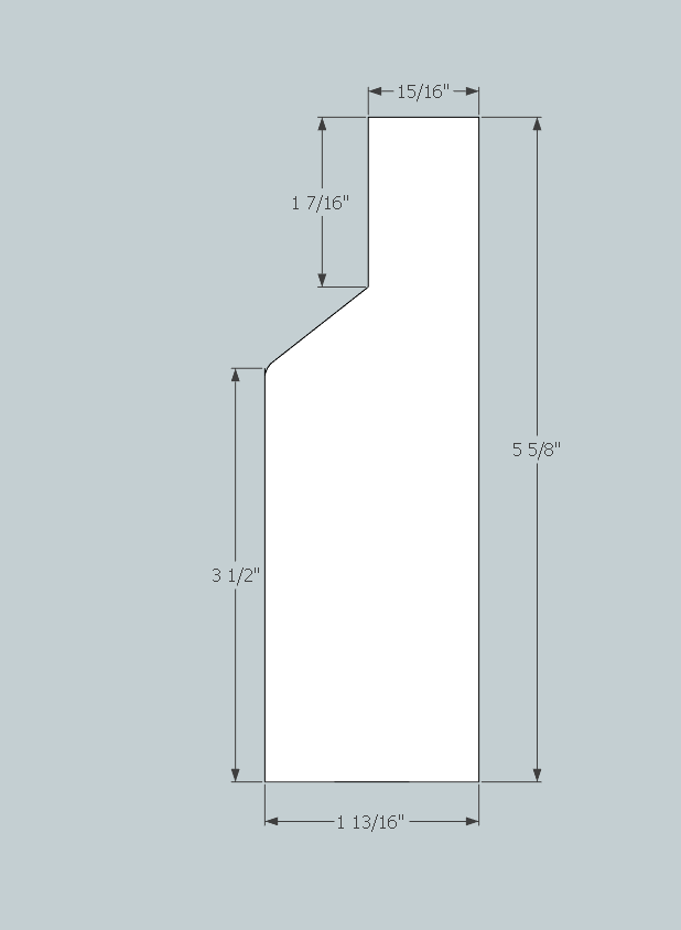
I’ve also started work on the gearbox but it’s taking a while as you can imagine. I’m trying to use photos from Chris’ build to help understand the different tapers he found while also referencing pictures and plans. I feel I have the base of the model pretty close and only need to add in the rounded edges and fins:
I’ll hopefully have something closed up on the gearbox early next week.
Edit: Whoops, my EDA and PPD are 1/8" too tall. The height off the motherboard for these pieces should be 3-1/6" (acutally 3-3/32" but I’m not sure we’re getting that detailed).
I’ve been away the past few days, so I apologise if the project seems to have stalled.
It would appear that the Julz pack its on the money, and a great deal of time could be saved by documenting it.
Would it be possible to get someone to measure one of these packs, and I’ll do the drawings, in consultation with the rest of you, from there?
It’s pchrisbosh1 lovely pack not mine… I just brought the thing 
I do not mind taking measurements and photos for you but that would have to wait till after Halloween…
There is no rush, and that would be greatly appreciated, Julz.
Thank you.
Should we ask him to see if he minds taking dimensions off of it?
I’m not sure I follow, why use a pchrisbosh shell for measurements?
I’m not sure Ben
That’s just what he asked for…
Chris’s shell and Neils shell are most accurate shells out their I’m aware of, and obviously Neils shell even more so
As far as i’m aware the production shell does suffer from some measurements here and there because of the process of the original mold having shrunk. I’m fairly sure Chris used the production shell as a guide for measurements as well as ones he had researched himself from the actual heros.
In the end of the day I don’t mind where the measurements come from as long as they are as accurate as we can get them.
It’s my understanding that the measurements for these packs were referenced off the originals, and represent the closest authenticity to a hero pack at the moment.
How would you suggest we proceed?
I don’t believe I’m qualified in this case to suggest a path to follow, I was curious about the suggestion of following a fan-made shell for measurements.
If Chris’s shells are satisfactory, then I won’t stand in the way of that.
I personally think that we should try to extrapolate the measurements from reference photos and/or get input from other builders. I don’t think we should be relying heavily on fan made shells. That said I do agree Chris and Neil’s shells are probably the most accurate (I’m not sure what updates have been made to the bigi shell that’s sold in the shop…so perhaps that’s pretty darn close now too).
I think those shells could be a source to check our measurements against to see if we came up with the same but I don’t think drawing plans strictly off of (or mostly off of) a fan shell is right, or morally correct. Especially if we don’t have permission. An argument could be made that taking measurements directly off of a fan shell without permission could be in a gray area of recasting. (Of course arguments could be made against that thought as well). Again I think we should be getting measurements from photo reference (and/or testimony) and then see how it stacks up against shells. But the decision really should be off reference unless the creator of those shells have given permission and/or shared their measurement conclusions. Thoughts?
Also were there any more thoughts on the following questions/comments below?
It would be nice if those measurements in question could be listed on the model. If I did my math correct, the base (wide part on motherboard) is 5 3/16" in the model which is different than both my opinion and Cole’s.
Anybody else have thoughts?
I’ll add the dimensions tonight.
@Kingpin - I think we’re all qualified to suggest a path. I would hate to sound like I want more say in this than anyone else, but if it’s agreed one fan pack is extremely close to an original pack, and is certainly more accurate than the current Stephan blueprint, I would be for reproducing those measurements.
Having said that, I’m still happy to extrapolate measurements from reference photos of we can start with known measurements for each piece.
If I look at the ribs picture, the end looks to be 1/16" past the 11" mark. The other side of the rib looks to be at the 10-9/16" mark resulting in the total width being 1/2". Since we know for almost certain that the fins are 1/8" thick, this means the rib extends past the powercell face 3/8".
With regard to this comment:
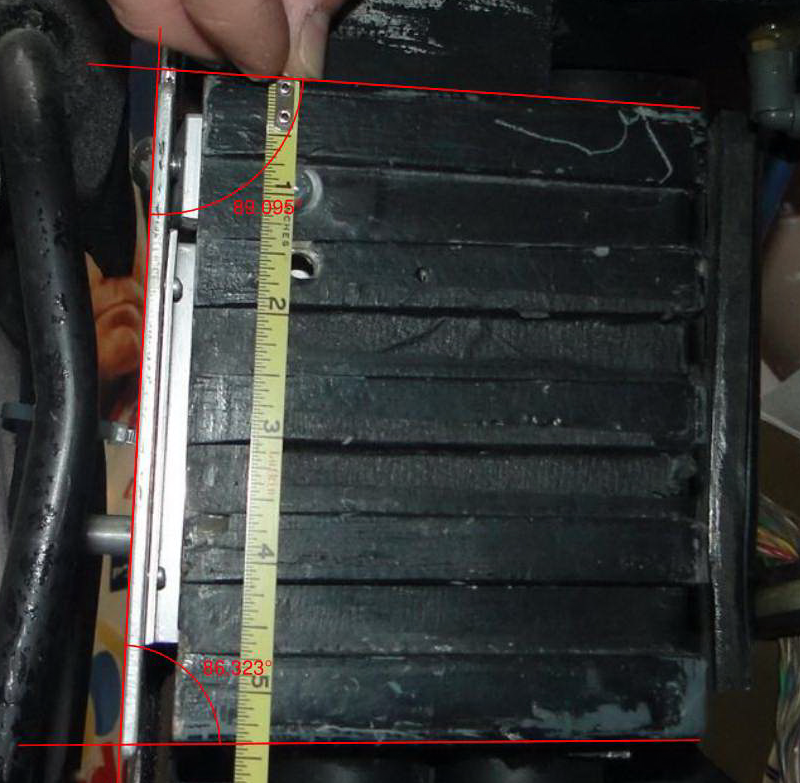
I wanted to verify and see if there was an angle at the top (as I’ve been assuming there wasn’t). If I draw a line along the motherboard and look at the top and bottom of the powercell, I get the following angles:
The top comes out to 89.1 degrees with the bottom being 86.3 degrees. Since this isn’t a perfectly lined up picture, I would be inclined to assume the top of the powercell is at a tangent with the motherboard and the bottom fin is at a ~2 degree angle with the motherboard. Assuming then that the top doesn’t taper, the bottom measurement can be read as the 5-7/16".
At the top, you have to remember that there is a 1/8" radius on that edge. If the fin was not rounded and came straight out, I believe that it would come to 5-5/16". Once you add in the 1/8" radius though, it starts to look closer to the 5-1/4" you mentioned.
I’m of the opinion that while Chris’ and Venky’s shells are very close to the originals, we should do our own homework and use their shells as a visual reference for the overall shapes and layouts. Chris’ pictures of the gearbox have helped out immensely with my own model so far.
I’ve kind of been building my own model in the background so whichever way you guys decide is up to you!
I disagree. It think the top rib tapers in slightly.
It would make the most sense to me to have both sides taper in.