I think you misunderstand what I mean by double checking. We wouldn’t be coming up with measurements from photos and what not, **and then **going back to change them to make sure they match the fan made pack.
What I mean is to see if there are any details we missed that could be explored. There are lots of details that we just don’t have good photos of, and assuming that, that part of the pack is considered to be accurate, we can look toward those packs for help. As others have said, there is still a lot of information on those packs that is accurate and is not even mainstream public knowledge yet. Why repeat research that has already been done and discovered by others… let’s utilize the knowledge that is out there. (with permission of course).
Overall. There seems to be some kind of confusion about how these two packs can be useful toward this project. I think a lot of people are getting hung up and cannot see the potential to having them as an **additional **reference point. We’re not making plans based off of them… but it is important to have as much information as possible. The outline I posted is a step by step process. You start with actual measurements, then use photos, then make an educated guess… etc.
Last step is look toward the two packs referenced above.
Well said AJ, that’s very much how I feel about all this.
My vote would be for a true hero shell. And I’m happy to help with illustrator image resizing for measurements from reference images on this site, I’ve already done quite a bit of that already for my own build.
My opinion on the history of the shell differs very slightly from Vince, in the fact I think the base of the shell was cast before the hero’s were complete, that shell was then used for both hero and stunt as they were built along side each other. Some of the details on the HMS stunt shell as bang on to the hero’s that I don’t think they would have gone out of there way to make sure they replicated them if they were doing completely separate scratch builds of both.
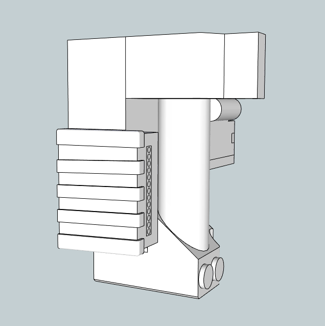
GB2 Semi-Hero again doesn’t give the impression of a taper on the top fin. When looking at how the EDA is angled along with the Ion Arm, it makes me think that the powercell is perfectly in line.
My model lined up like several of these pictures. The point I’m trying to make here is that this photo kind of gives the impression that the top fin is at an angle when really it is at a perfect 90 degree angle to the motherboard.
I actually think you might have something there regarding the top taper. I loaded the earlier shot of the side in to photoshop and made 2 versions to look further into what you are saying. The one on the left has just been rotated so the pack side and motherboard are straight. The one on the right I had a crack at trying to take into account the perspective the picture is taken from. All I did was use the perspective tool to scale the top out equally until the fins lined up in length with the bottom ones. It’s not quite perfect as there is now a slight taper going backwards but its a pretty good experiment supporting your argument… Possibly a nice find there Cole
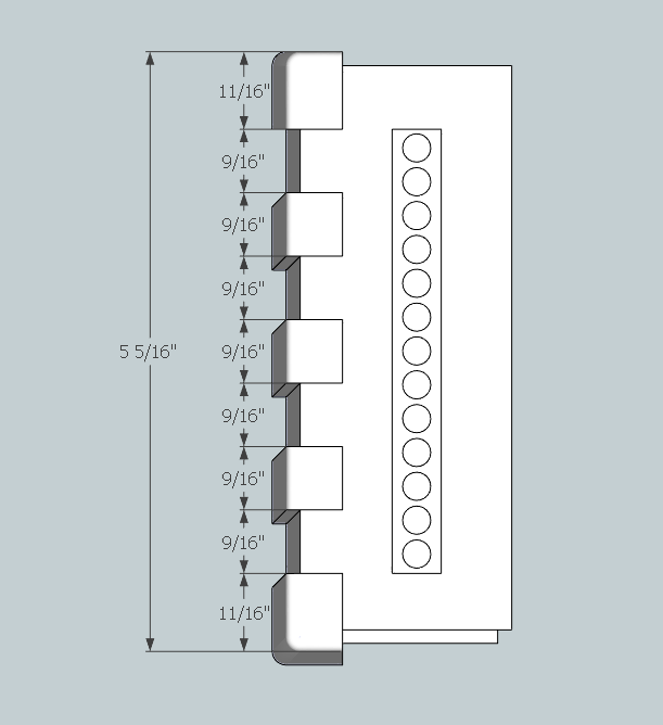
I have been bouncing back and forth on the taper myself. Sometimes I think it does, other times I don’t. I think the biggest thing I am stuck on right now is the actual dimensions of the ribs/spaces at the motherboard and farthest away. Even if I went with the 5 7/16" at the base(motherboard) which I am leaning towards, and 5 1/4" at top (away from the motherboard) I come up about 1/8" not accounted for, and even more if we use the current dimensions listed.
I’ve been using the Photoshop ruler/analyse tool on the side of the power cell to confirm that the top surface is flat.
Using the same image as Julz, I see there is some distortion in the image, and I’ve taken into account the fact that the power cell has moved free of the mobo.
The bottom ribs all angle up at an average distance of 0.19" and I’ll reflect that in the next model.
The ribs also appear to have a thickness of about .15" - which is about .025" thisker than previously measured.
Thoughts?
Have we reached agreement on whether the inside wall is parallel or tapered?
I think it is unanimous that we want plans based off a GB1 Hero shell.
My question is, do we want to model any of the defects? Things such as wavy or curved in parts like the surface of the Cyclotron… or do we want to leave those parts idealized? Most shells will warp in the same way when casting from fiberglass, so would there be any benefit to having stuff warped in the plans already?
(Not referring to draft angles or curves, but parts that were specifically warped from casting).
I personally love all the defects and warps… but that is possibly something that each person using the plans can decide to include if they choose to, it’s easier to put a dip in the cyclotron but harder to take it out.
Ramjet… powercell inner wall taper? I’m personally not aware of a taper there? I think it’s parallel no?
I am all for the GB1 hero. Now making this definitive is going to be the tricky business. Most of this is going to be based off one hero pack (Sony lobby/New York PH) with some coming from the Murray/ Minnesota PH and some coming from the Spengler.Truly the Sony Lobby pack is the most intimately documented pack since 2004.
That’s three out of the 4-5 heroes that were made, plus not all of them may suffer from certain physical distortions.
Do you disregard the narrow valley of the Spengler or do you side note it as a variation in the body.
What other cosmetic and physical properties do you account for or disregard?
The fact of the matter is that you may have chosen a hero direction, but it will be mostly based off only one of the 4-5.
This will be exciting to see what is included in these new plans.
Personally I am sticking to the 5 1/4" on the top (powercell side). The dimension in question I had was the width next to the motherboard. Where it meets the motherboard looks like these measurements, however it clearly looks like 5 7/16" - 5 1/2".
I agree that the powercell should be 5-7/16" at the motherboard based on the photos. I think Ramjet will be updating this in his next revision.
If you’re going to stick with 5-1/4" on the top, then I have to ask what dimensions from the model I posted you plan on changing.
I know the tape measure looks to show it at 5-1/4" in the photo, but that means you then have to eliminate 1/16" from one of the sections (either a fin width or the spacing between them).
I personally believe that each fin was 9/16" in width on the original prop and 1/8" thick. This means the top and bottom fins would come out to 11/16" and the three others would be right at 9/16". I also believe that the spacing between the fins at the top of the powercell come out to 9/16" consistently (as shown in my model). Adding all of those together results in the top coming out to 5-5/16" long.
**NOTE: To me the top rib is smashed…It doesn’t follow the line to stay 11/16". At the base it’s probably a little wider, more like the 3/4" and the space is probably 11/16" (right at the motherboard).
I would like to quickly voice my opinion about this process. As there are so many known issues with Stefan’s plans, I believe they need to be disregarded and new plans created from the ground up. There is so much more information now that when those plans were made and after more than a year of personal experience with them, my extremely careful extrapolation of measurements and knowledge of construction methods, his plans just cannot be relied upon.
I believe that using a shell like Venky’s, that has a credible and verifiable lineage to an original GB1 shell, is the only shell that should be referenced for measurements. I agree that Chris’ shell is close to Venky’s and is indeed a very nice shell, but as others have pointed out his remains a fan made shell using known information, photos and lots of research to create his shell. I spent more than a year drawing measurements by comparing several photos from different angles, caliper measurements and pages upon pages of mathematical calculations. Even after all my work, there are inherent errors as there are on any shell made by this method. It is impossible for anyone to recreate something that is truly exact unless one were to take measurements from the object directly. In short, if a mold were made from an original GB1 Hero shell, the only shell that would drop into that mold, or at least that would be the closest fitting, would be Venky’s.
I chose to make my shell idealized since the real shell has issues that appear like errors to me. That is my personal take. However, I believe that any new GBFANS plans should reflect how the GB1 hero packs really were with all the details precisely represented.
I have a funny feeling there are a few changes for the eda, the corner below the left eda disk has a large bevel and the angle where the booster tube meets the eda also springs to mind, I’ll do some research and get back to you…