valentino_42's Scratch Build - I came, I saw... I Finished!!

After seeing the clever way that Gareee was able to fashion his pack, I knew I wanted to take a crack at making my own pack.

Over the last few years I’ve done some home remodeling and various other projects, so I had a surplus of all sizes and kinds of scrap wood - so plenty of starter material for a wooden pack.

I’m making all of my electronics and lighting accessible from the front of the pack, so that means customizing the pack to make this work out. I’ve also decided to add some custom features to “make the pack my own”.

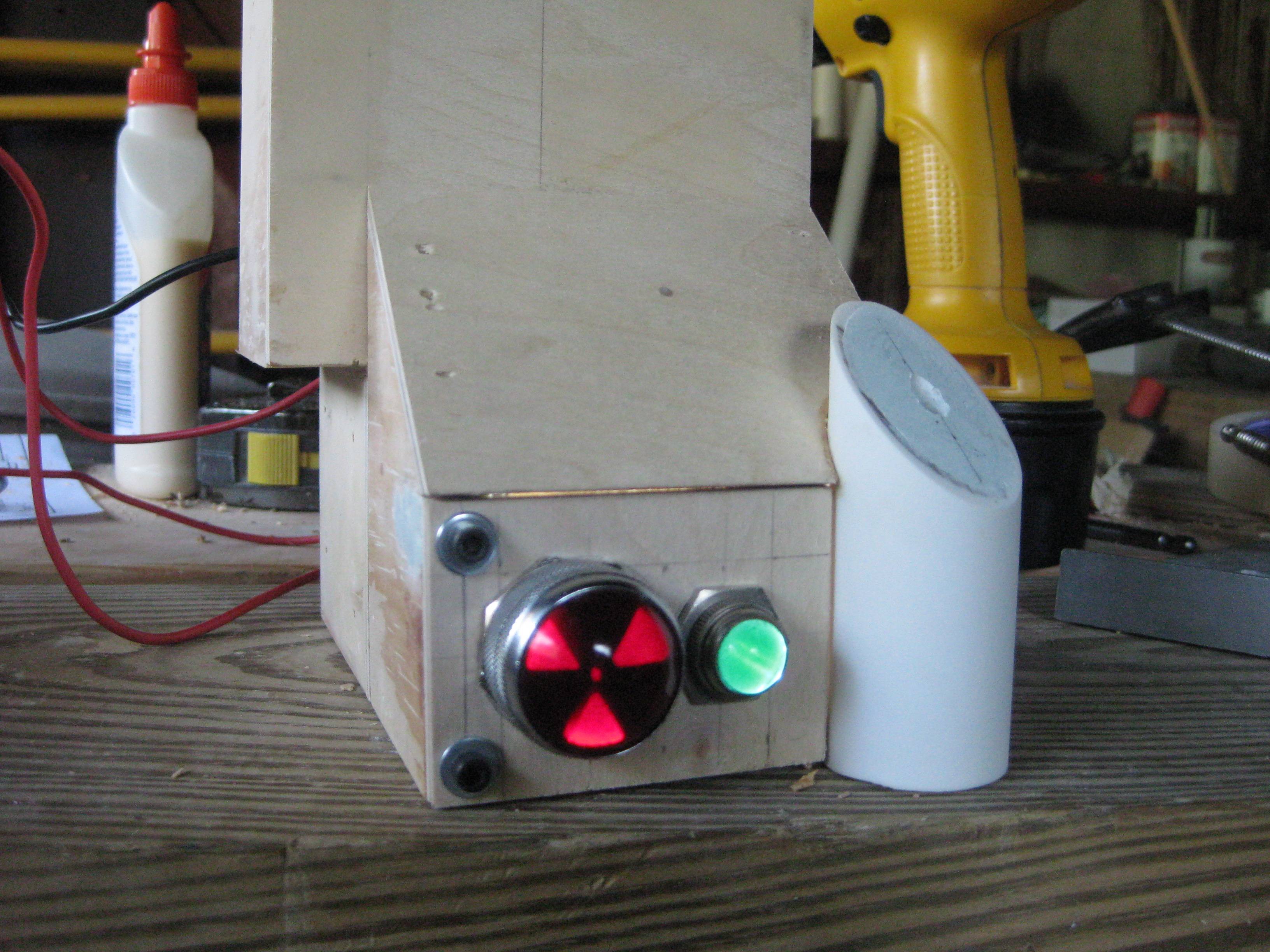
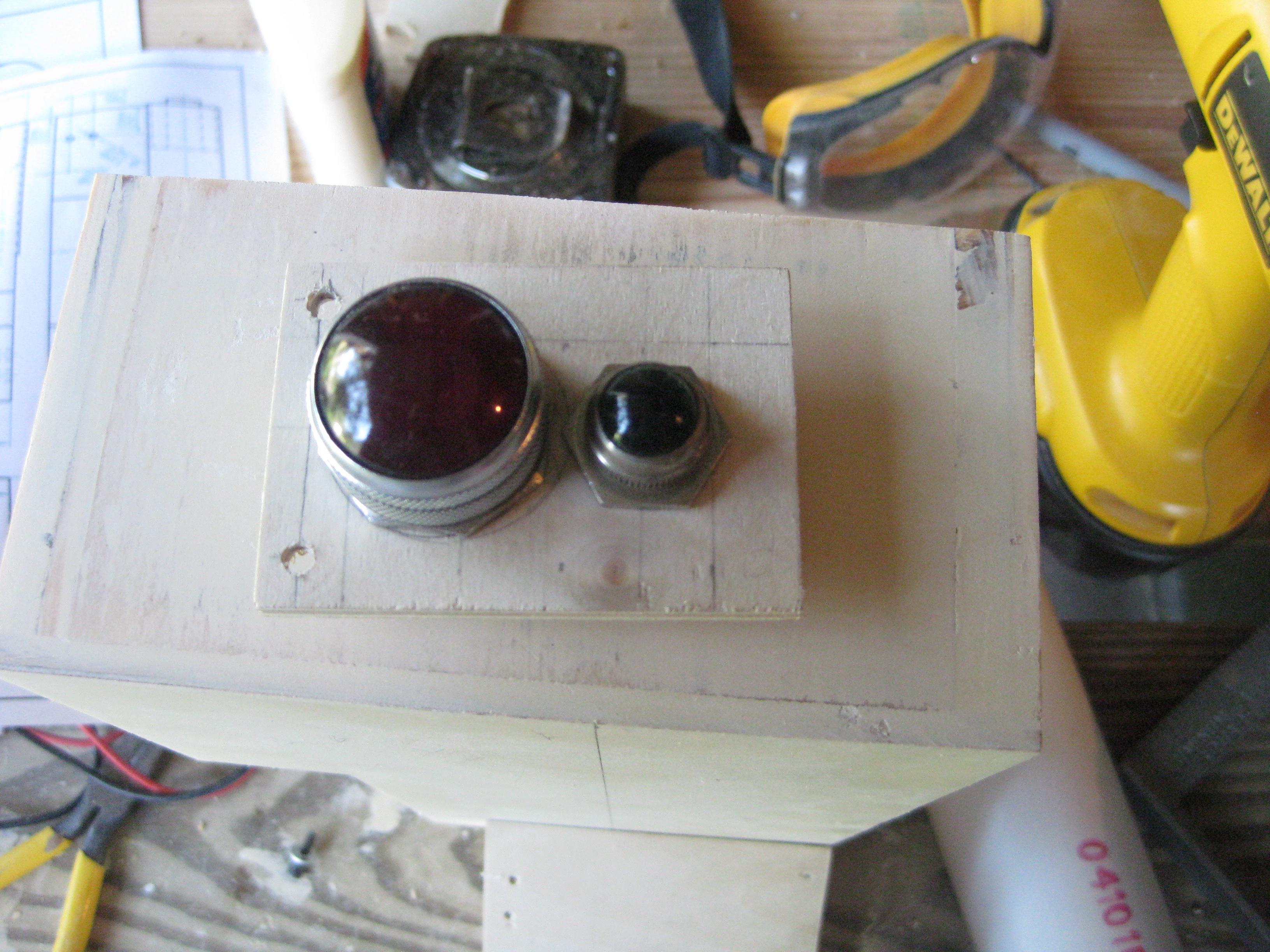
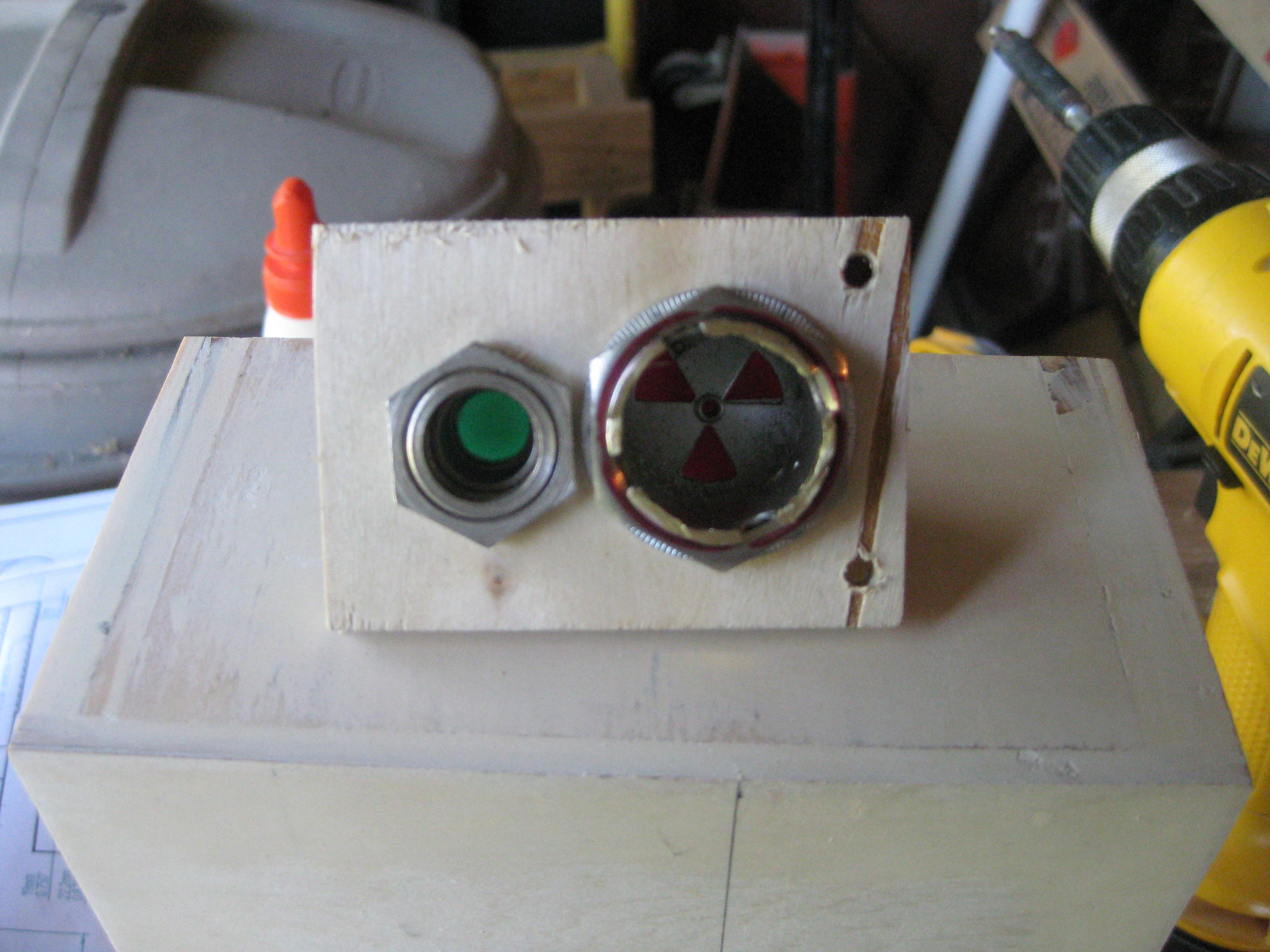
For example, my wife’s parents own an antique business and while rummaging around there a month ago, I came across these glass light covers from old industrial machinery. I’m putting these little light domes where the small useless circles go on the booster/eda box to jazz it up a bit. Please keep in mind that this is all pre- wood puttying and finishing, so I know things are in rought shape.

Here are the domes:

Backside of the domes:

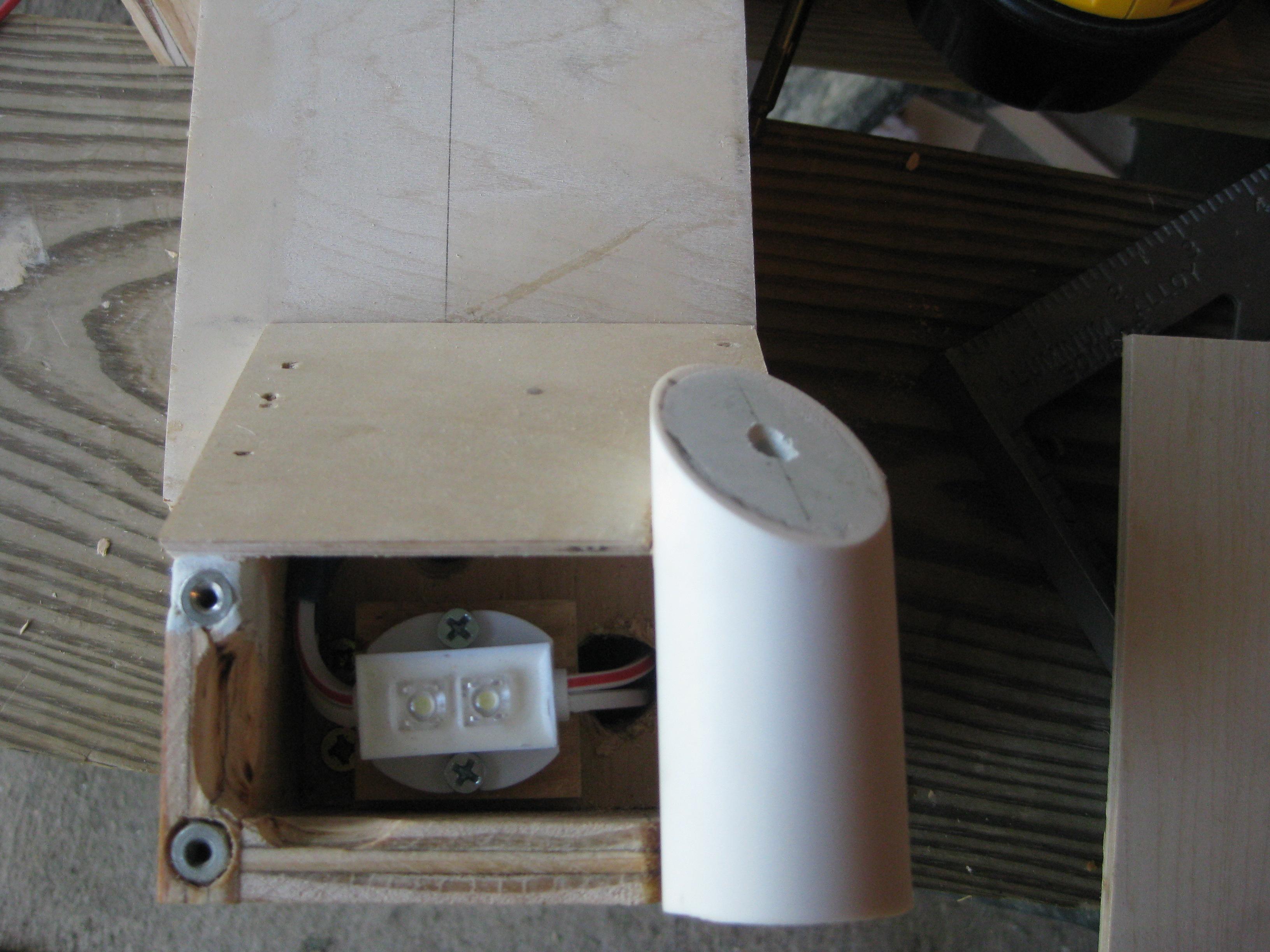
The inside of the booster/EDA box with my superbrightleds.com lights:

Here you can see of I’ve made the setup accessible from the outside with allen head screws. You can see a little light seeping around the edges of the cover. I plan on making light traps out of foam to prevent this once I’ve got all of my parts together.

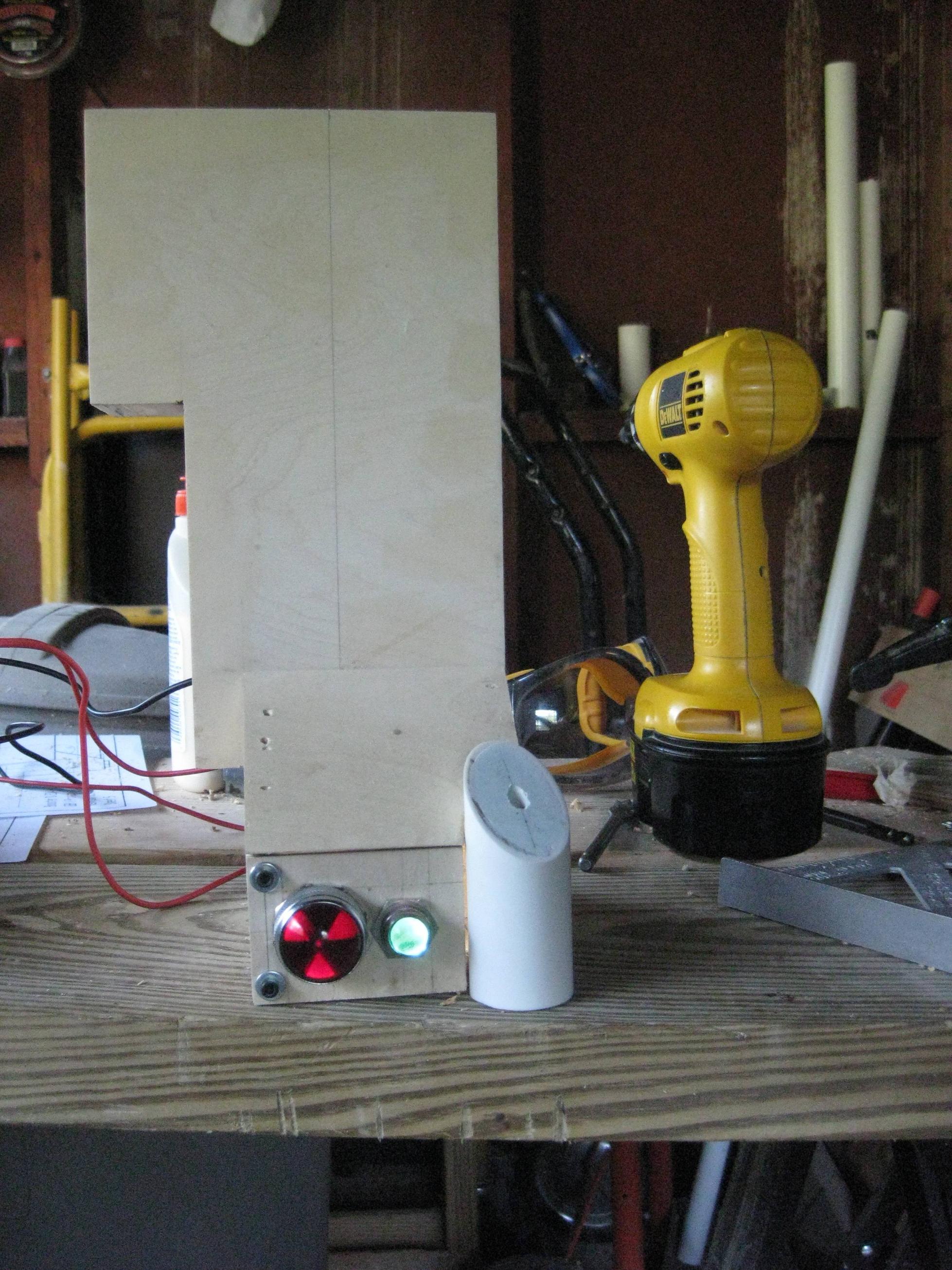
Another shot of the whole assembly:

I’ve actually got a decent start on several other parts that I will post in the coming days, like the cyclotron, the spacer, and the power cell.

Those domes look neat…very steampunky and retro.

So far it reminds me of an RGB pack or an XGB pack. Look foward to seeing where you go with this…

G

Thanks for the compliments!

I like the additions so far! If you want to get rid of that light bleed from the edges easily, just staple some cloth or thin rubber around the edges. Old bicycle inner tube makes great rubber for something like this, but you can also buy small sheets at Lowe’s.

Someone recently did a great improvement idea for the cyclotron with cake pan… they fit in in from under the top of the sync generator, and then did a proper lip with foam core. If you use the larger cake pans from walmart, that will give you an excellent cyclotron shape.

Also, make everything removable if you can. That way you can easily repair/upgrade. I wish someone had mentioned that to me during my builds.

Personally I LOVE the radioactive sign. Keep up the good work!

Ok, before I forget…

All of the “components” of my pack will be made with 1/2" diameter plywood sides with 1/4" front faces. The spacer is wood stacked together with the the area behind the cyclotron cut out to save weight and provide space.

I’ve got a sheet of really nice 1/4" plywood and a sheet of 1/2" plywood left over to choose between for a motherboard.

I’d really like to use the 1/4", but I wanted to get everyone’s thoughts on if it will be beefy enough to mount everything to… plus it will help keep the weight down, if only by a little.

Thoughts?

My motherboard’s made from 1/4" luan wood, which isn’t as sturdy as regular plywood. It’s more than sturdy enough for the rest of my pack, which is primarily luan and plywood. So, 1/4" ply should be plenty sufficient, I’d think. Though, you may want to consider the Luan as an alternative, since it’s closer in thickness. 1/4" ply runs closer to 5/16", while 1/4 Luan runs more like 3/16". So, it’s only 1/16" too thick, as opposed to 3/16".

Chris

Ok, finally had some time to snap pics of what I’ve already got done.

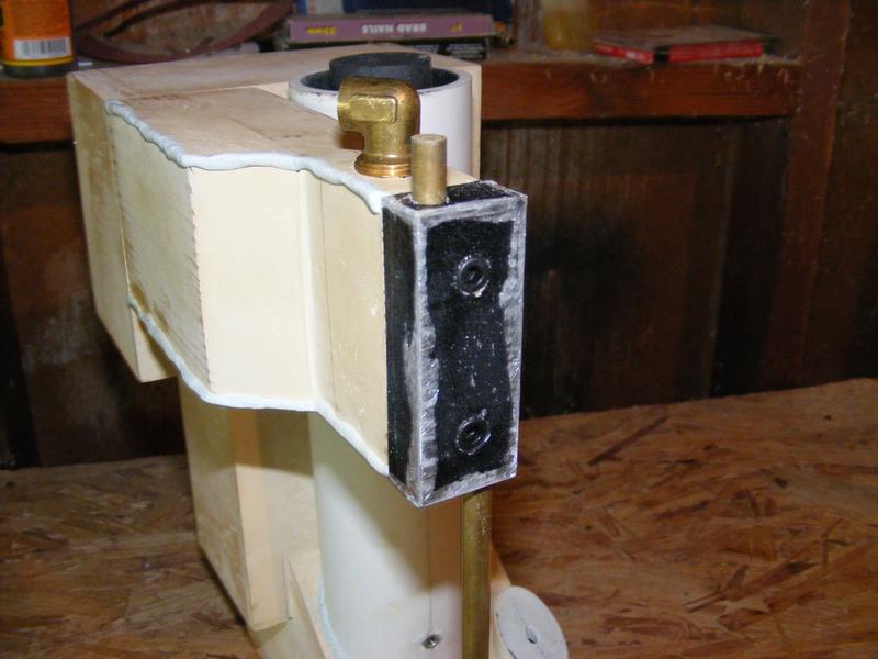
The ion arm: includes fake welds. The end is a block of wood that I wrapped with aluminum tape, scuffed up, and painted. The brass rod is actually brass tubing with the ends filled with epoxy putty and painted with brass paint.

I was originall planning on making my own fake resistors out of small pvc pipe with IDE cable glued to the outside… My mockups looked great, but when I glued up my finals, the epoxy didn’t set. It set me back a few days… I was a little upset. Anyways, ended up ordering the Multimedia Mayhem GB2 resistor set and they just came in the mail today, so I’m itching to put them on there.

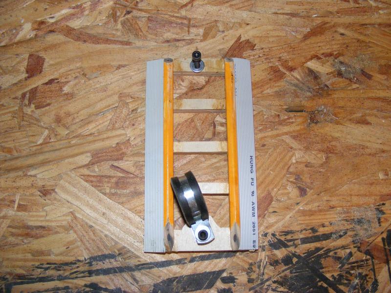
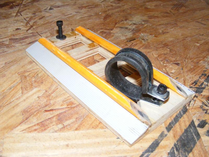
The booster ladder frame: 1/4 luan plywood double stacked with real honest to god pencils. Ribbing accomplished with old floppy drive IDE cable. I decided to forgo the brick pattern on the “rungs”

It is in need of a good puttying/sanding still…

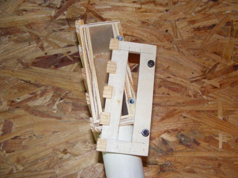
Power Cell: As I mentioned before, I’m building this so that all of my lights and electronics are accessible from the front. This meant altering the plans to include some more allen screws to hold on the face of the cell.

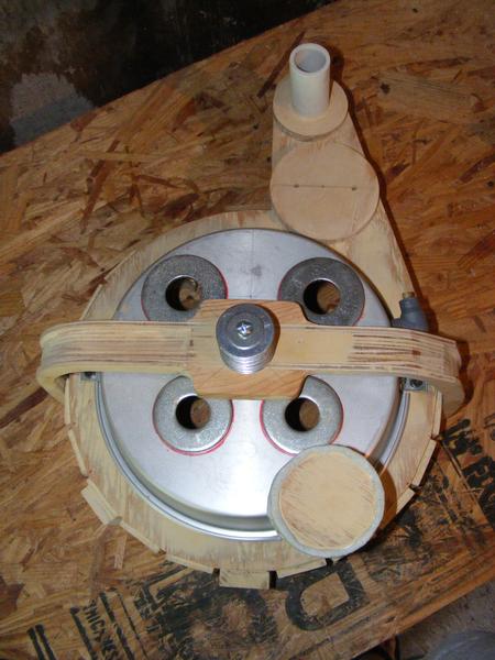
Cyclotron/Spacer/BumperEtc: I actually started my build with the spacer. It’s scrap wood that’s layered one on top of another, I then used a hole saw to punch out the excess under the cyclotron. I then cut a nice finished piece of half inch ply for the top layer with a neat hole cut out to go under the cyclotron.

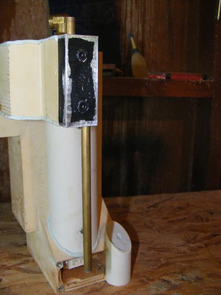
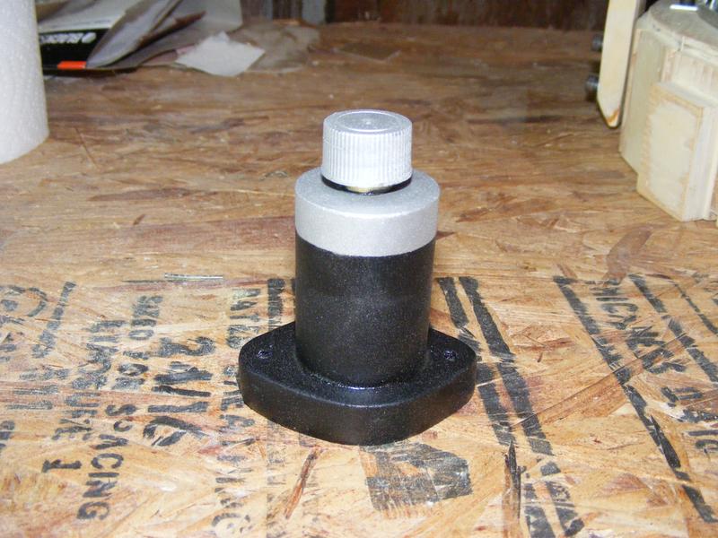
My fake clippard valve made with a plywood base, a pvc pipe, a plywood end fill piece, a dowel rod, and a Louisiana Hot Sauce cap for the valve (it’s the PERFECT SIZE!)

Bumper: Made from two layers of 1/2" ply cut to “interior dimensions” and pieces of 1/4" luan cut with “outside dimensions”. I think it’s like 1/8" shy of being perfect, but I think it turned out really well. Just cut scrap wood to make the “wings” in the center. Still in need of puttying and sanding.

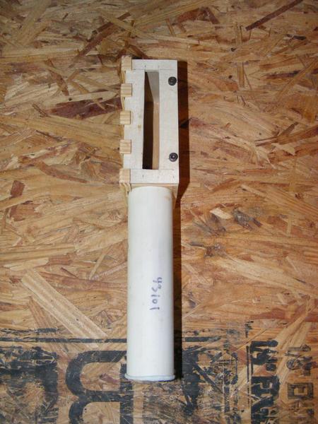
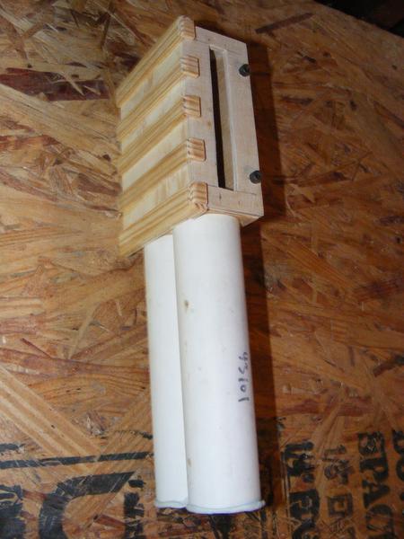
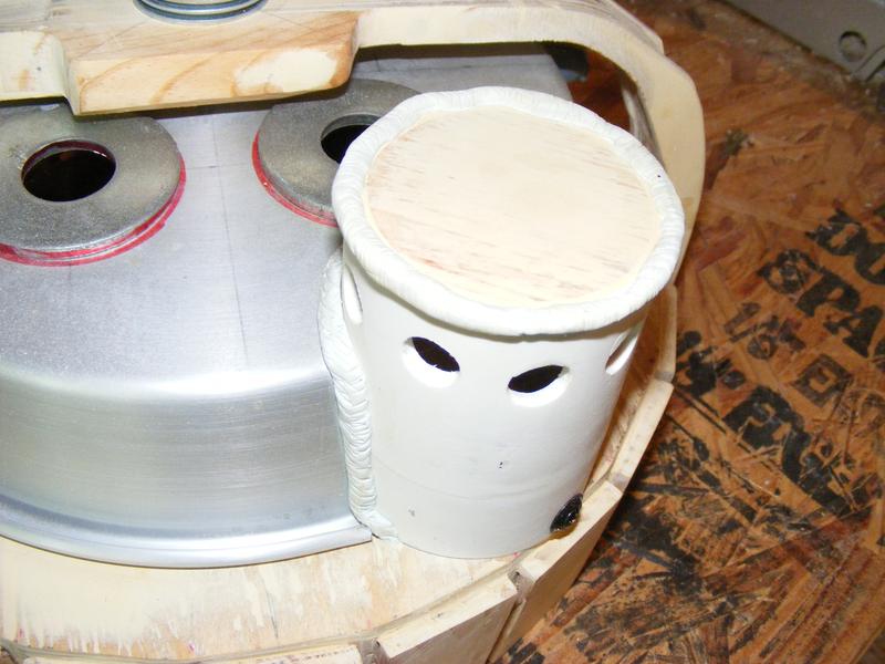
N-filter: two pvc fitting glued end to end and cut to the correct height. Capped off with scrap plywood and a fake weld. The plan is to put a cut paint roller inside it and finish off the holes with gridded drywall sandpaper mesh to complete the “filter” illusion. Wish my pic wasn’t so washed out…

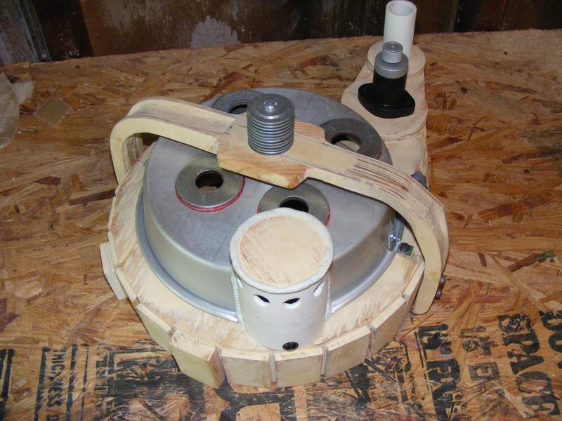
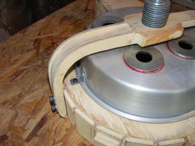
More on the cyclotron: To make it front accessible, I recessed coupling nuts into my spacer and used small L-brackets with allen head screws to make my cake pan removable. You can also get a better look at my bumper here.

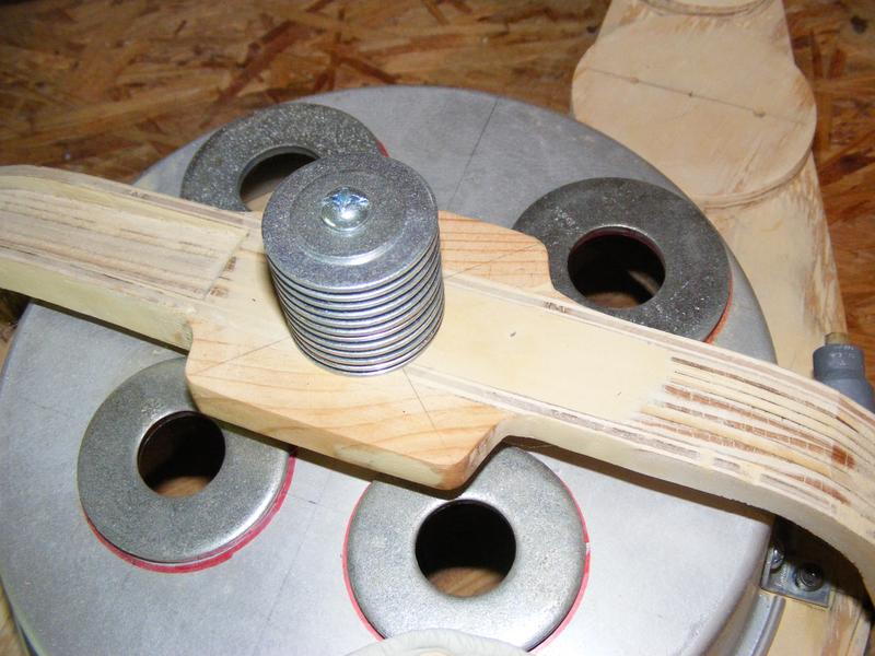
Shock Mount: Stacked washers. Larger washers are real metal, inner, smaller washers are plastic to cut down on weight.

I’ve made fake legris elbows out of grey fittings and spare brass tubing. You can see one on my cyclotron here:

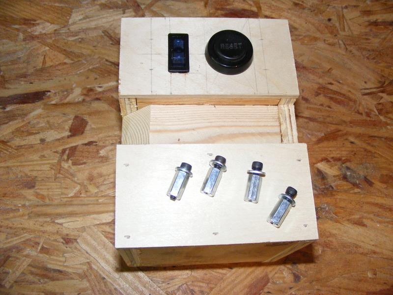
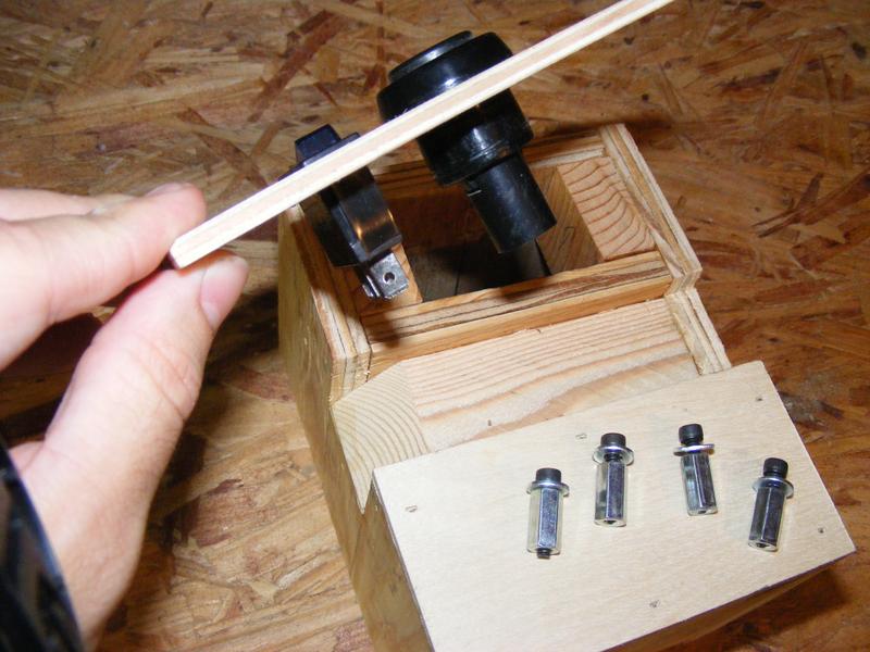
The gear box, another part I’m actively working on. Once again, this is a part I’m customizing. No Raytheon crank knob for me… had a friend find some old very large “Reset” switches, so I threw one on for looks. The blue toggle switch beside it is lighted, and will be the on/off switch for all of my pack lights. The faceplate will once again be attached with recessed coupling nuts and allen head screws. Still a lot of work to do on this part.

Any questions, comments, concerns, violent outbursts?

I rushed in getting these pictures taken, so I know there are some other angles and shots I’d like to get. If you have something you’d like to see that isn’t pictured, just let me know and I’ll snap a new pic.
Im very impressed with what you’ve done so far. Can’t wait to see more!

This is scratch-built genius. And I love the customizations.

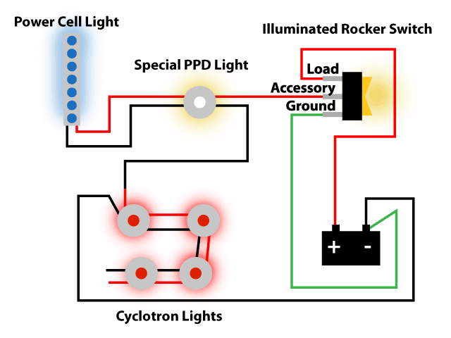
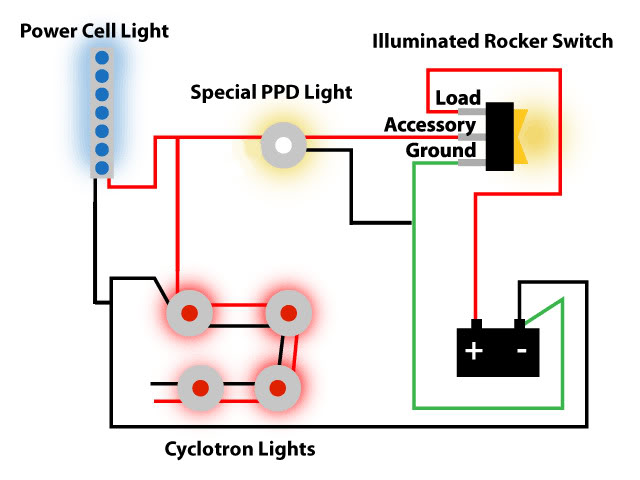
I’ve started wiring my pack, but I’m having some trouble.

Hopefully my illustration makes sense.

First thing to mention, My “Special PPD Light” and Cyclotron lights each have two positive and two negative wire coming off of them. They are LBM2 led modules from superbrighleds.com LED Lighting for Everything | Super Bright LEDs

Power runs from my 12V battery to my lighted rocker switch, then out the accessory lead to my Special PPD Light. It then goes through the power cell lights (which are LB3 light strips from superbrightleds.com LED Lighting for Everything | Super Bright LEDs)negative wire back through the negative wires on the PPD Light. I then switch back to the positive wires of my cyclotron, and out one of the negative wires back to the battery.

In order for the rocker to light up, the ground needs to be connected, and I figured it needed to be put back on the negative terminal of the battery to complete the circuit for the light inside the rocker… and it did light up for about 5 minutes, then it got really bright, then it burnt out. I’m assuming this is my problem. Where should this wire connect?

All of my lights still work except for the rocker light. The rocker still turns everything on and off. What am I doing wrong that caused the rocker to burn out? Any help is appreciated.

My guess is you didn’t put any resistors in the circuit and there was a current overrun. You have to limit the current going through LEDs or they’ll blow.

Does it matter that these aren’t component LEDS? I was led to believe the type I was using could be connected directly to a 12v power source.

Also should mention that the rocker switch isn’t an led. It’s an incandescent.

What rocker switch are you using?

I don’t remember the brand off hand. I can check when I get home. It was a run of the mill illuminated rocker from Auto Zone with three prongs.

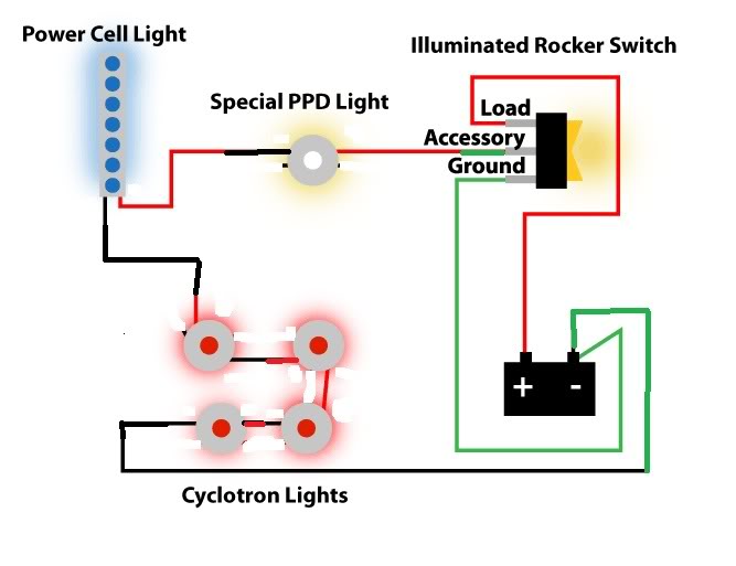
Hopefully someone a little more wiring proficient will tell you if I am mistaken, but assuming your rocker must be grounded as well, you should be able to simplify your wiring. As far as i can tell from your diagram and the photo’s I’ve seen, you should be able to do as follows, (Sorry I butchered your drawing)

Sorry but no help with the wiring from me. I will let those more knowledgeable speak up.

Just wanted to say I’m really impressed with your choice of lens covers. Those are really cool.

Looking forward to more pictures.

Ted.

I gotta say I really love the little customizations you’ve got going on! I love the Proton Pack, I love how iconic it is.. but it’s 26 years since 1984.. You’d imagine that a few tiny changes/updates would have been made since then! (not a complete re-imagine like EGB, but something, well, like this!)

Here, I fixed your wiring diagram:

You can’t use a ground from one item as the positive lead for another. The wiring for the switch should probably be changed around too, but since I don’t know what switch you are using, I just left it for now.

I have to say, this is an AMAZING scratch built. I am blown away by every piece you’ve made.

Keep it up!