Hi guys, and yes I know before you say, it is blasphemous to want to do this to a pack. But I’m planning on building “My pack”, taking various ideas and designs from various packs that I like and putting them all together.
One of which involves recreating a more “on purpose” version of the stantz pack powercell lights leaking out of the thin areas of the shell, which I believe the TVG pack included too.
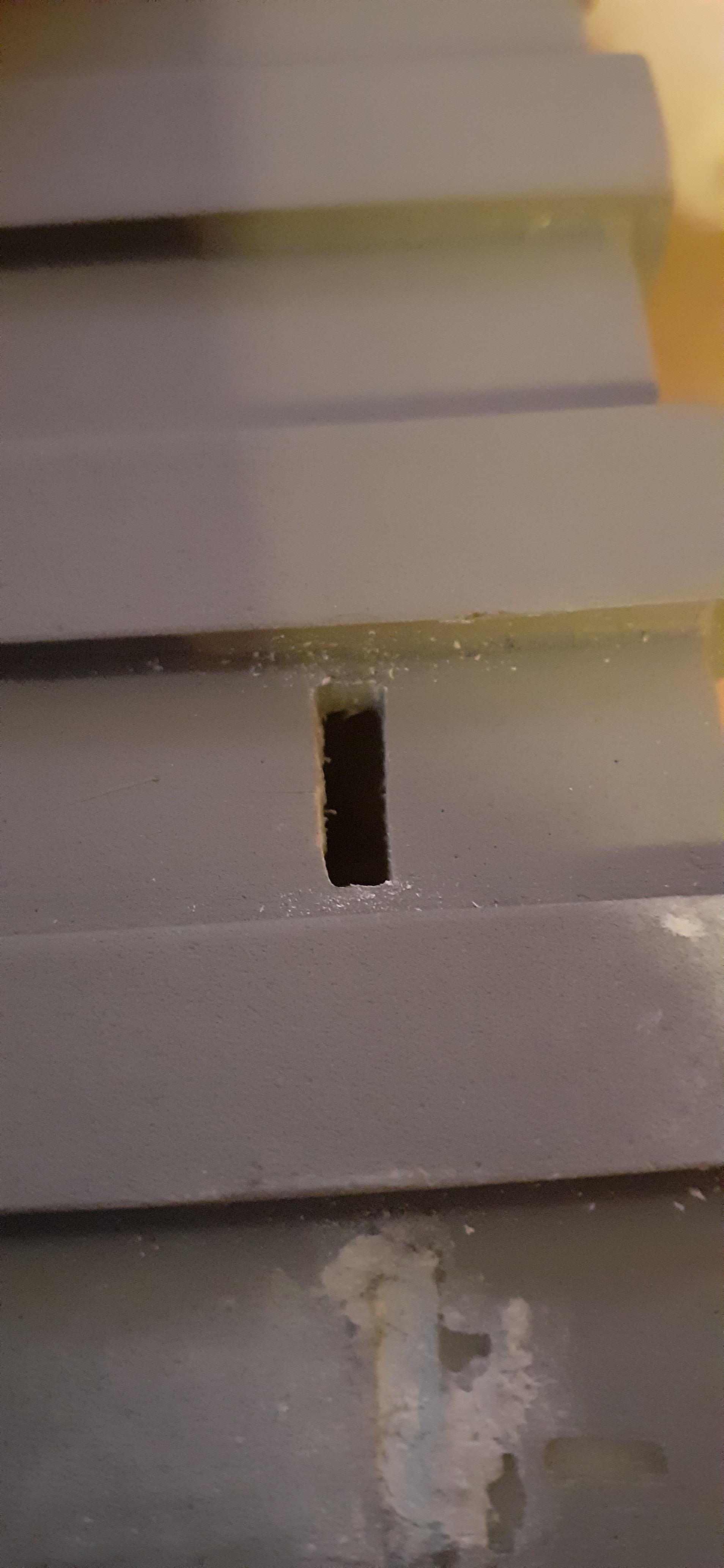
My question is - what would be the best method to cut out the small slits I have marked out on the shell cleanly? (About 8mm×2mm)
I was thinking of a dremel but I’m not sure if there is a bit that would be able to do what I need it to in such a small precise area?
Why Cut it out at all? If you have a fiberglass shell you should be able to sand the jell coat down to the resin and your done, doing It would even be screen accurate for rays pack.
In GB2 Rays Pack in The Court Room Still has the two spots on the powercell lights
Best bet would be those small thin carbon Dremel wheels. Or if you want something with more control / safer you could always drill very small holes on the line of the slits you want to create like “. . . .” then use a very small needle file to connect the dots into a line “___” File method would probably take a lot more elbow grease but would also work.
So since I’ve been making some progress with my pack I though I would turn this thread into a build thread (2 birds 1 stone)
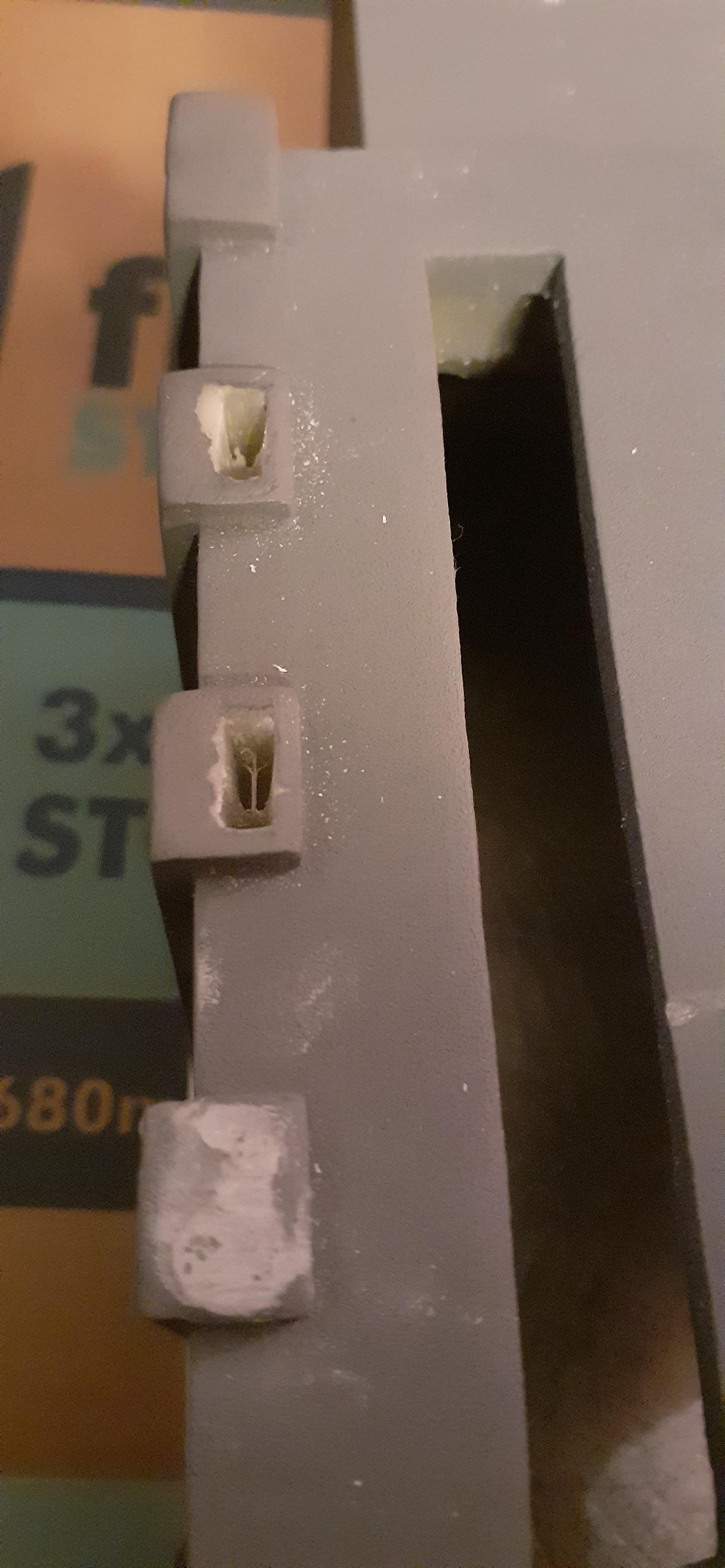
So to update I managed to somewhat successfully (the second time anyway) drill and file the slits into the powercell ribs, ready for small frosted perspex windows to be inserted after painting.
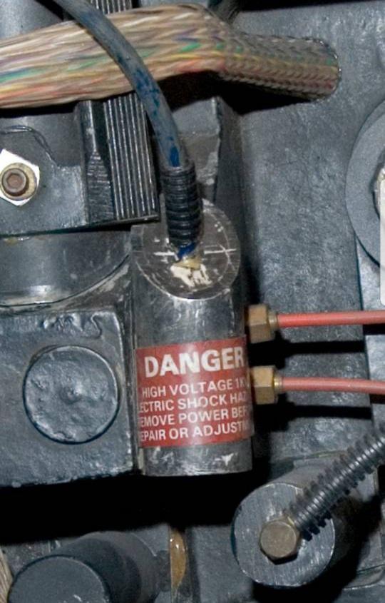
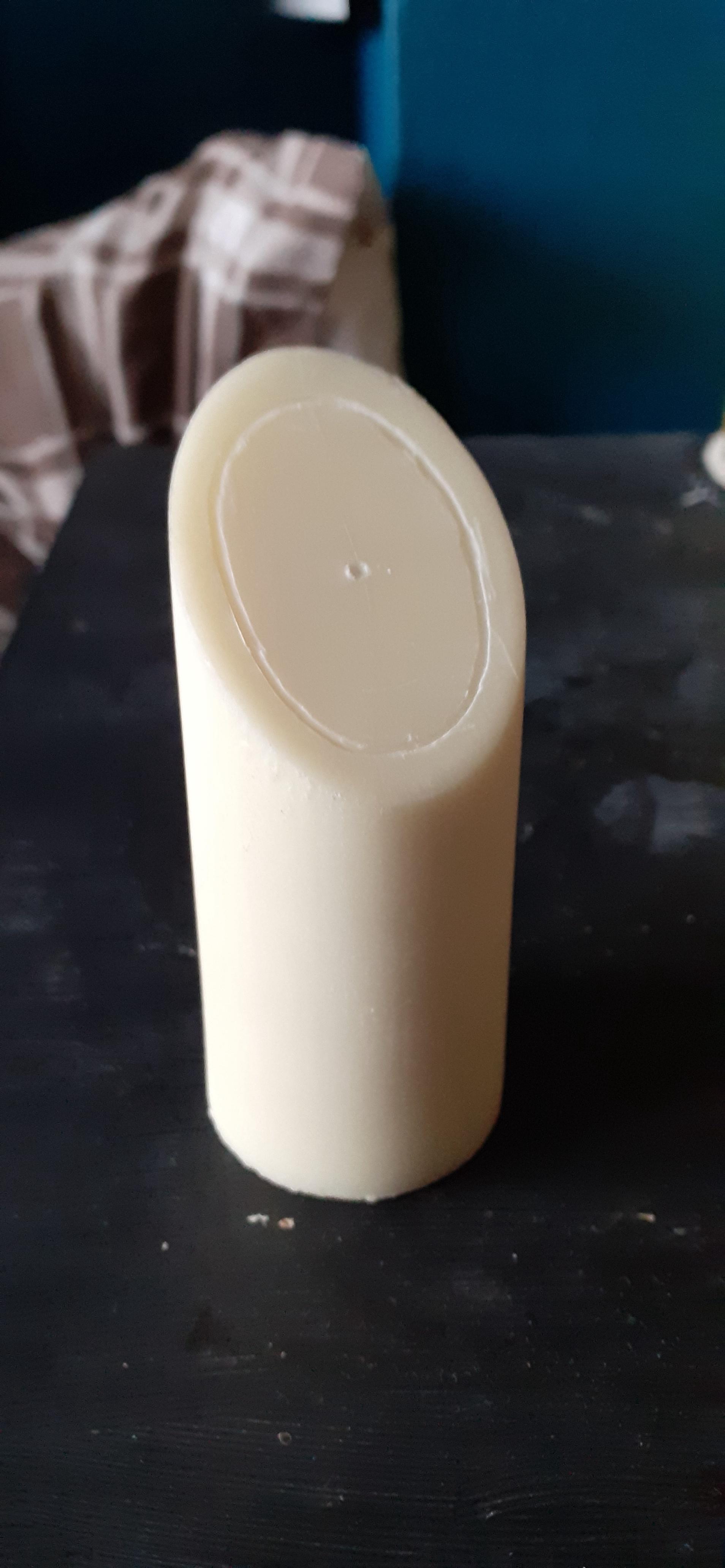
So to try and recreate the “filled aluminium tube” look on the resin PPD I used a scribing compass to trace the line of the outer tube ( with some difficulty) and then free hand the rest to make the engraving deeper.
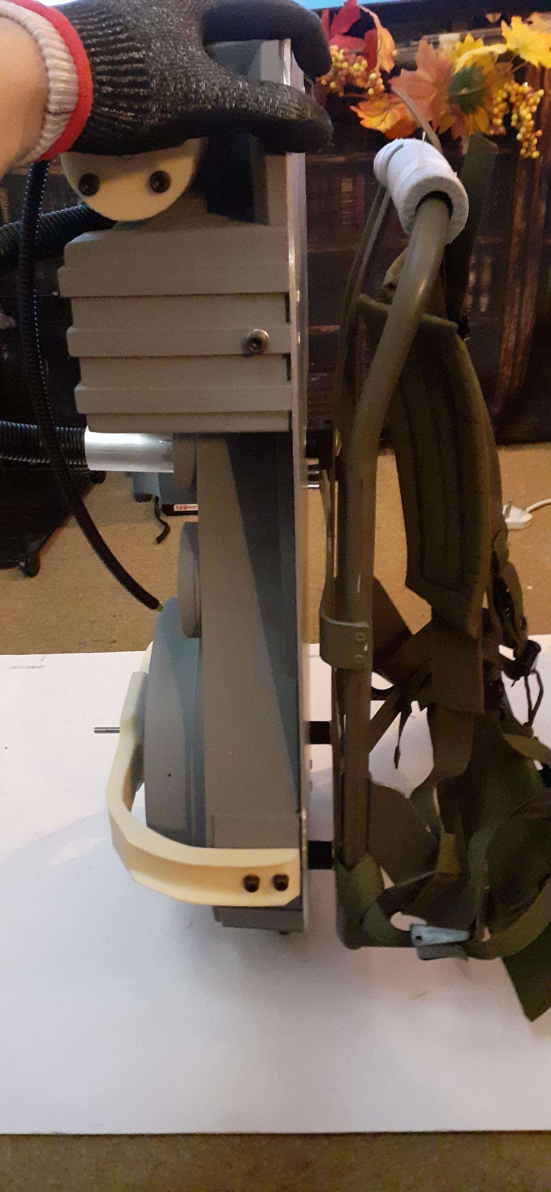
Luckily with some help and good old fashioned elbow grease, We managed to straighten out the bend and mount it to the motherboard with some sturdy m8 coach bolts.
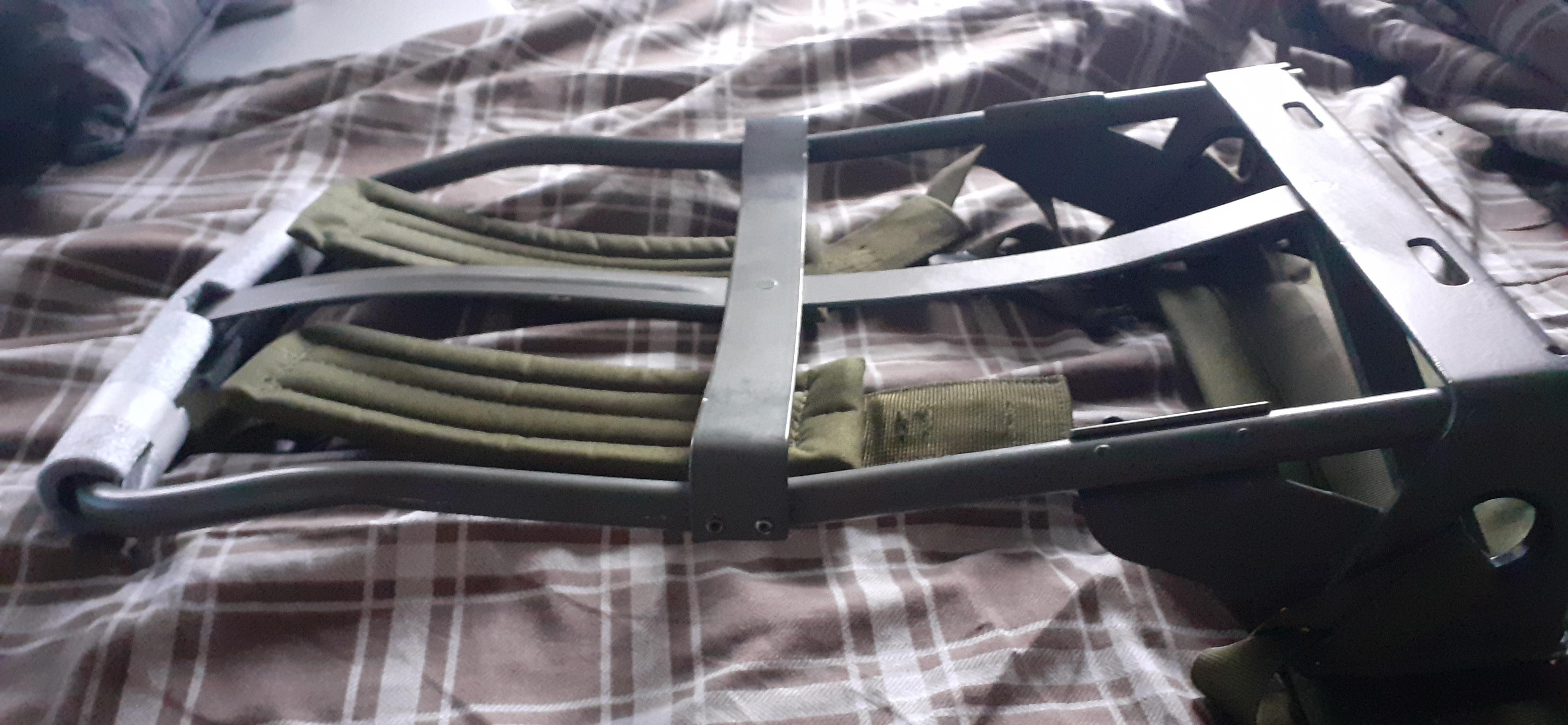
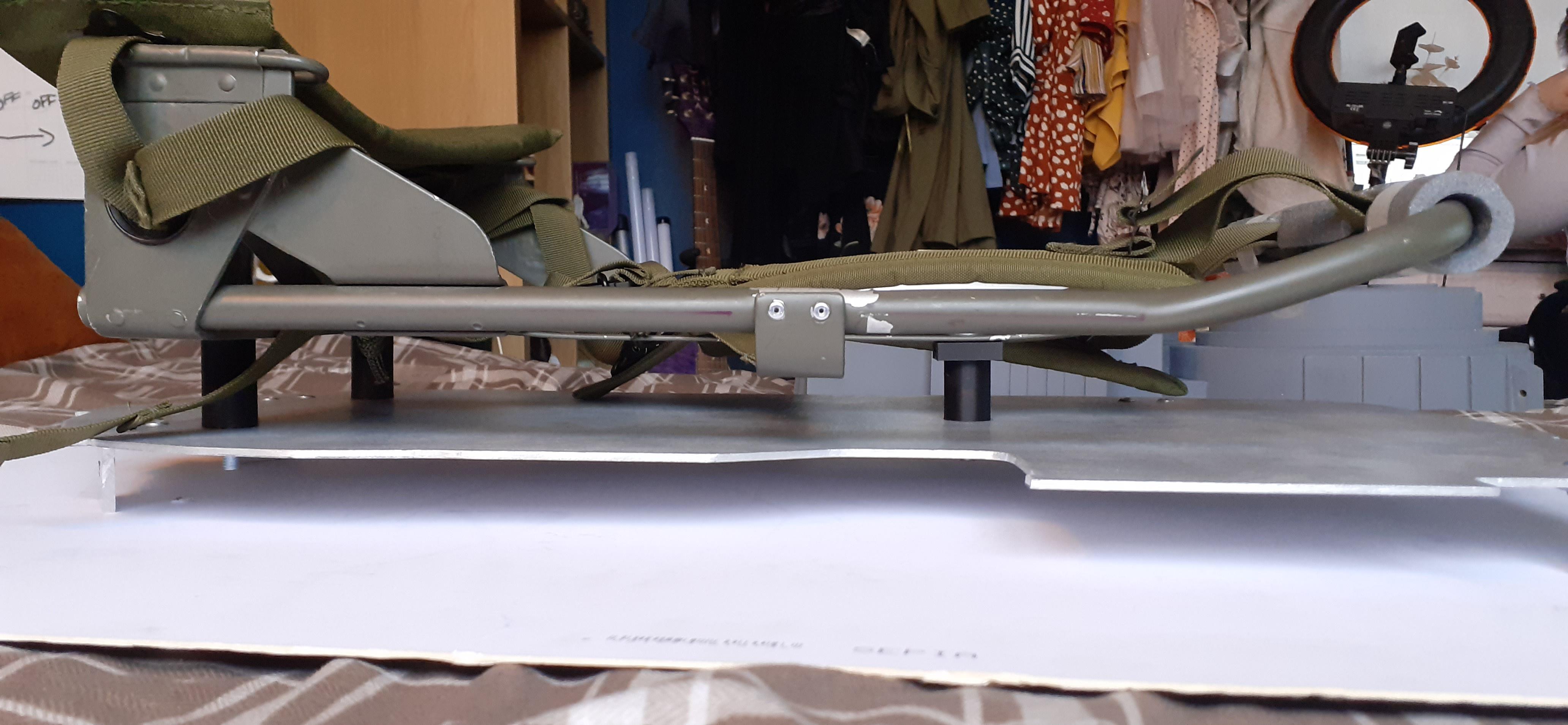
I’m not sure what to correct length is for the alice frame spacers, but comparing against reference pics it looks like the gap is a tad too big between the frame and the pa k?
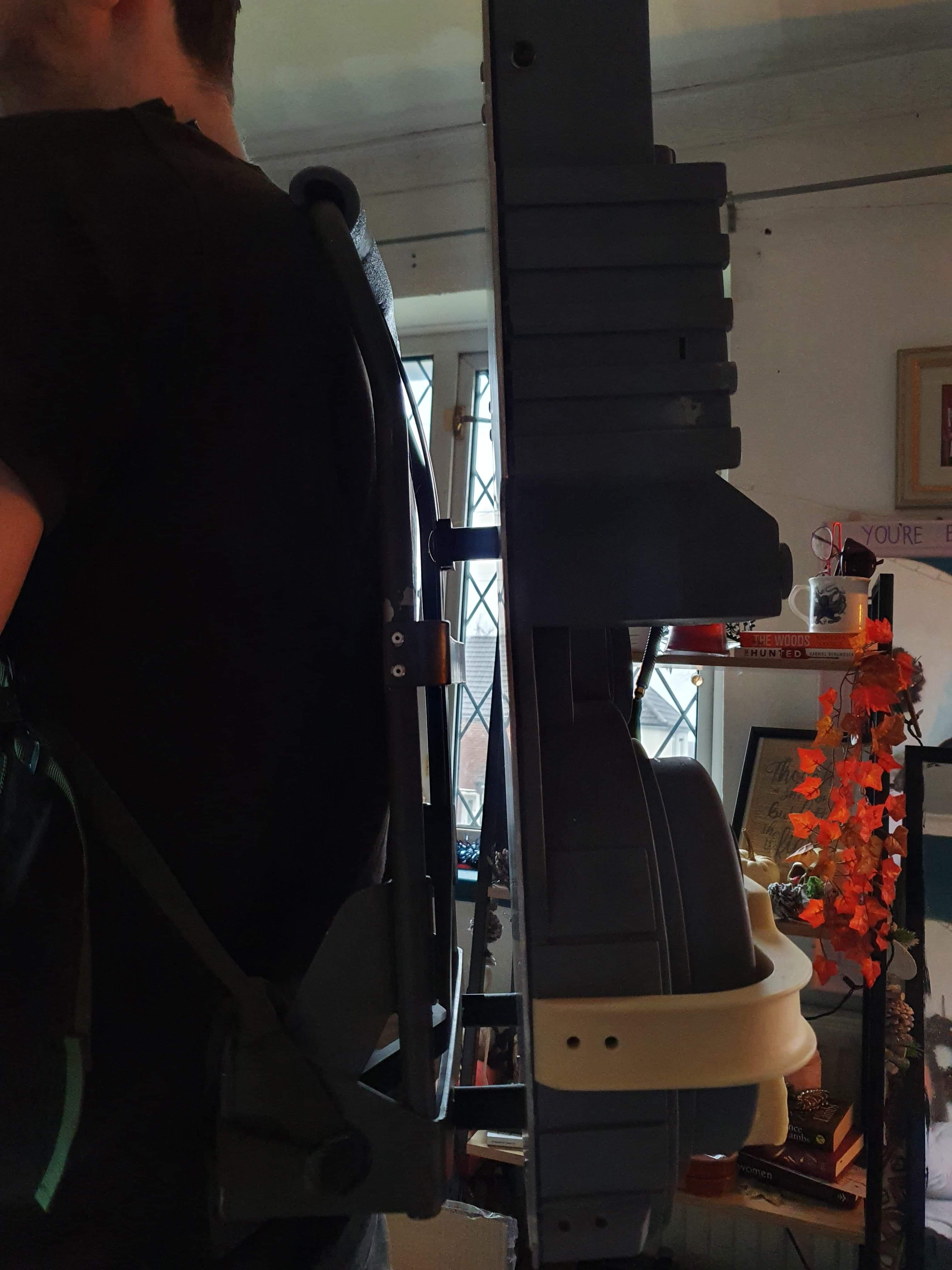
The feeling when putting a pack on for the first time…
Depending on the material thickness, I’d consider using your dremel to rough cut the hole, approx 1.5mm undersized, then use the barrel sander tip to open the hole out to the required size or trim line.
Good work scribing the cut-out on the PPD by the way, that’s tricky using a regular compass from the centre! See if you can find some odd-leg callipers for any other jobs like that, they measure from the outer edge rather than the centre and are much easier to use on non-level surfaces.
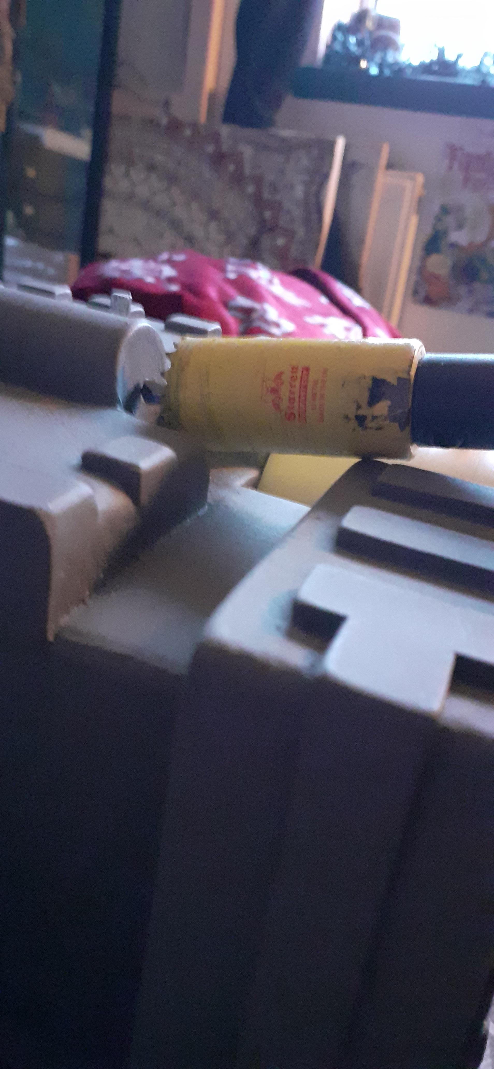
Thanks, I’ll use a 22mm cutter and as soon as I can borrow a dremel I’ll be on that
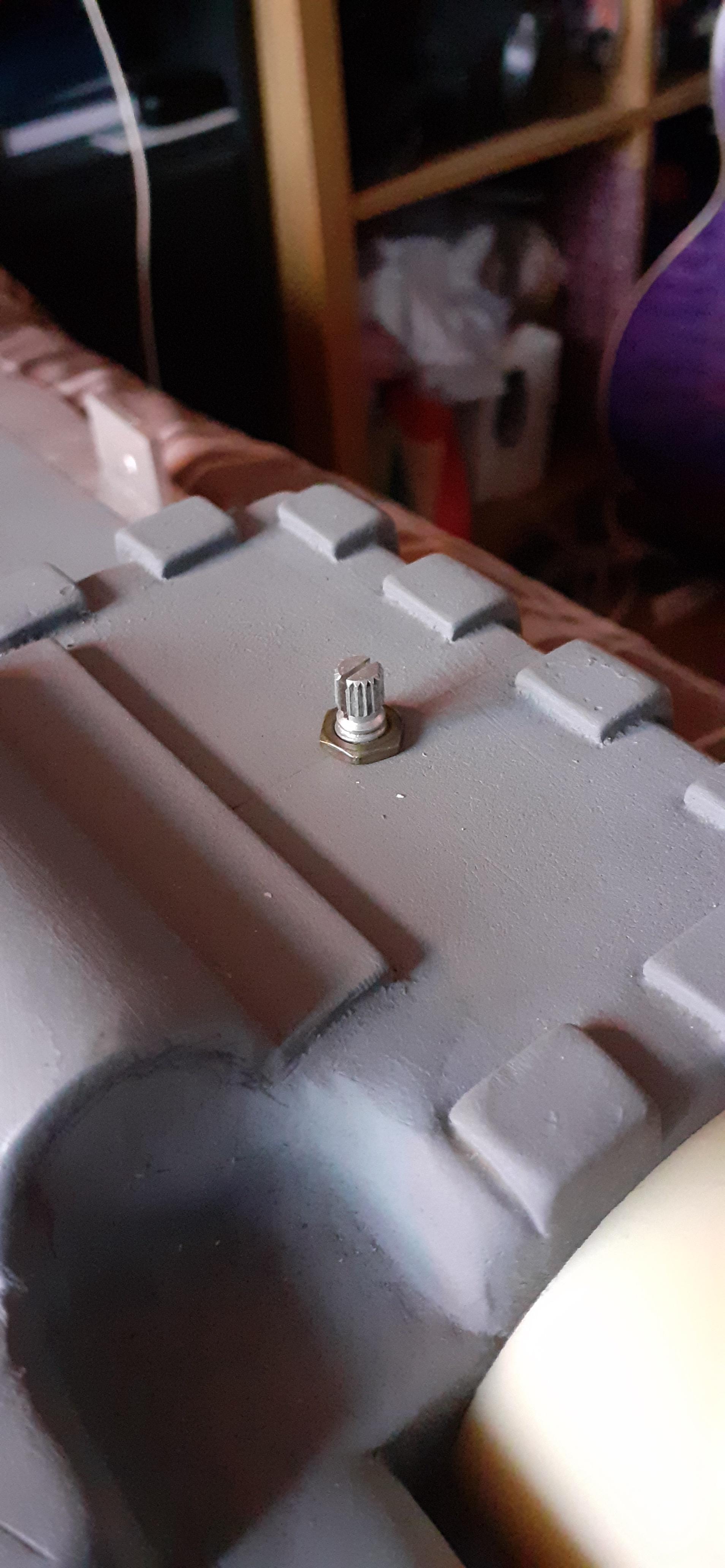
In the meantime I stripped a volume pot out of one of my old guitars for the crank knob that I’ve ordered from the shop, and mounted it ready. I did the same as I’ve seen others do and take the little plastic stop off the bottom so it can rotate freely.
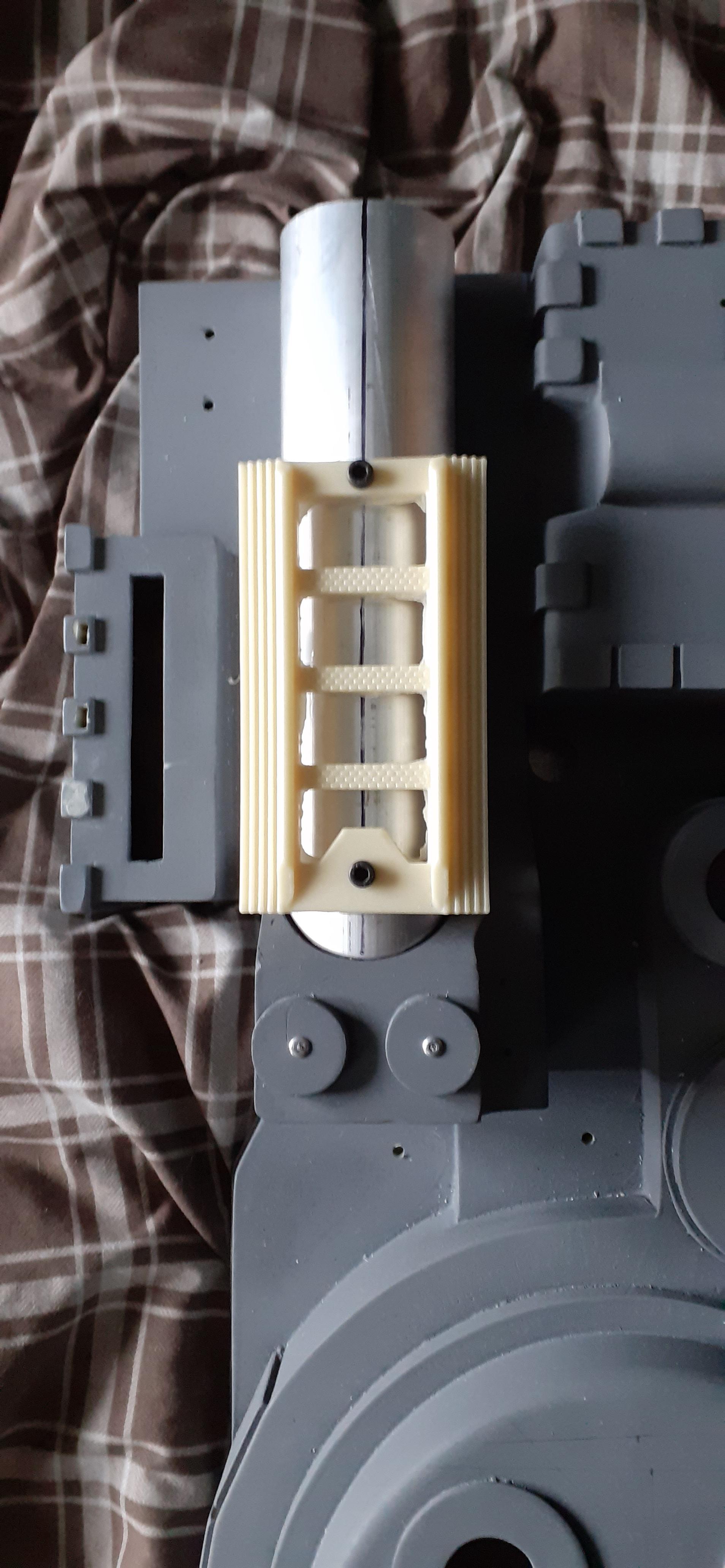
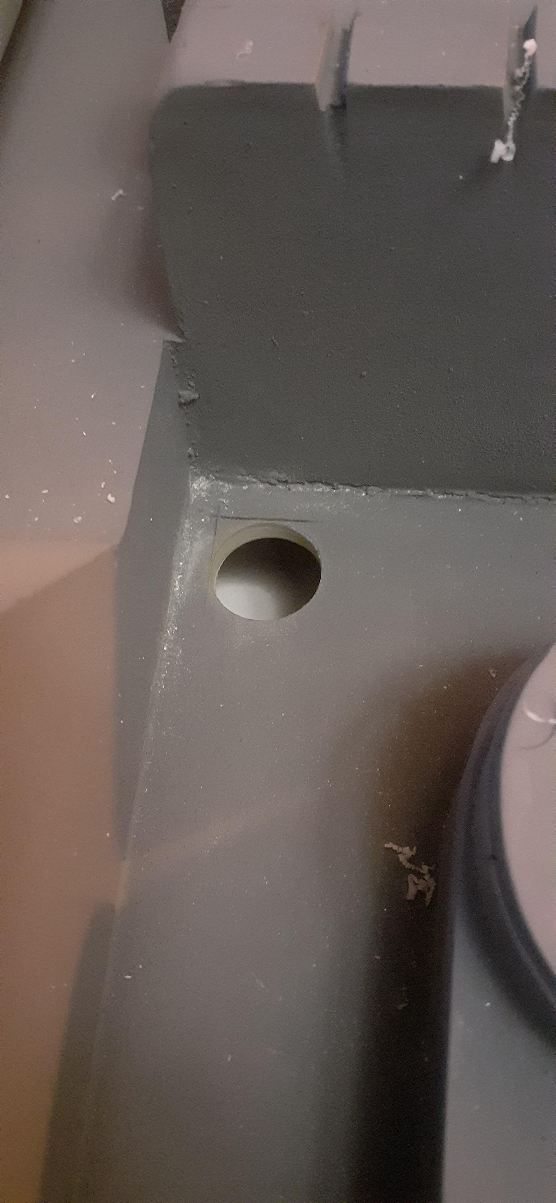
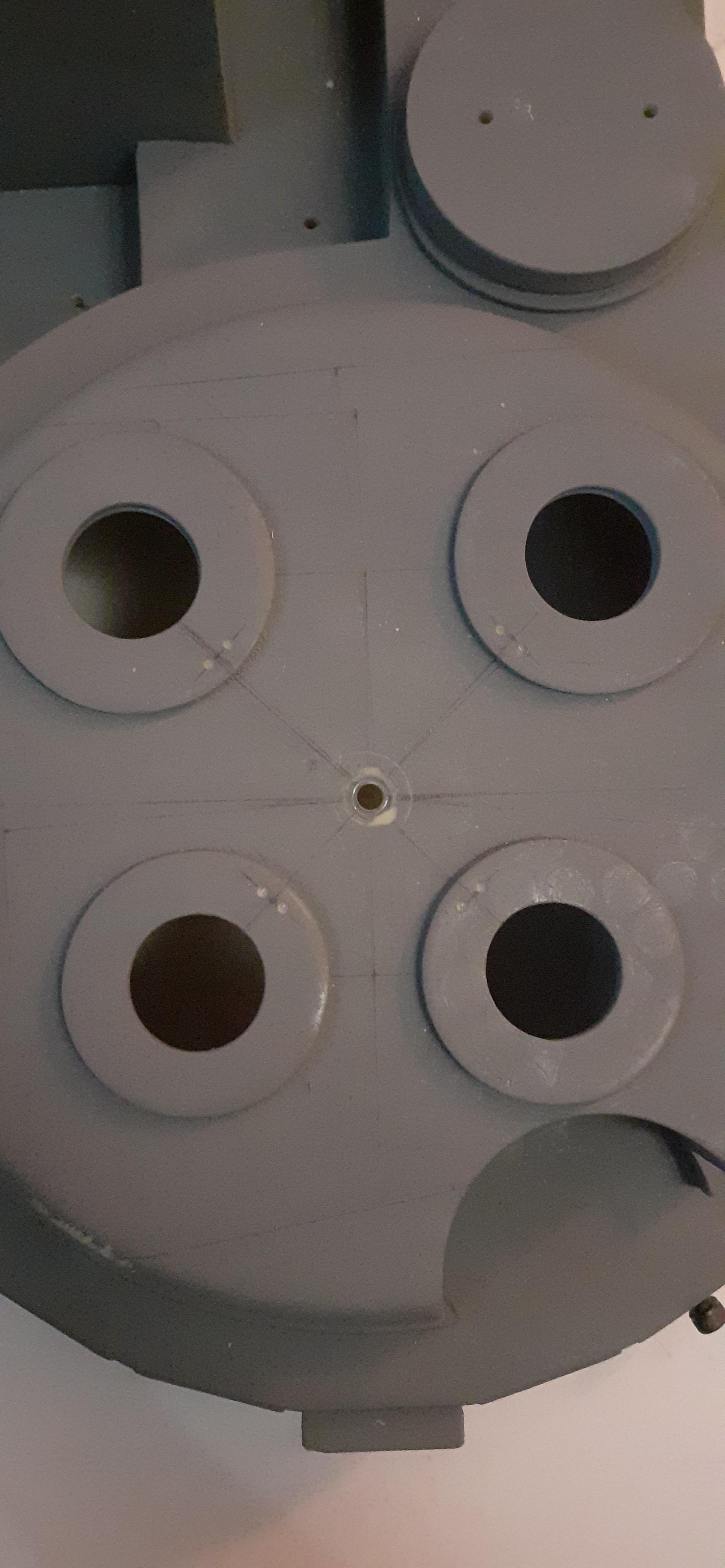
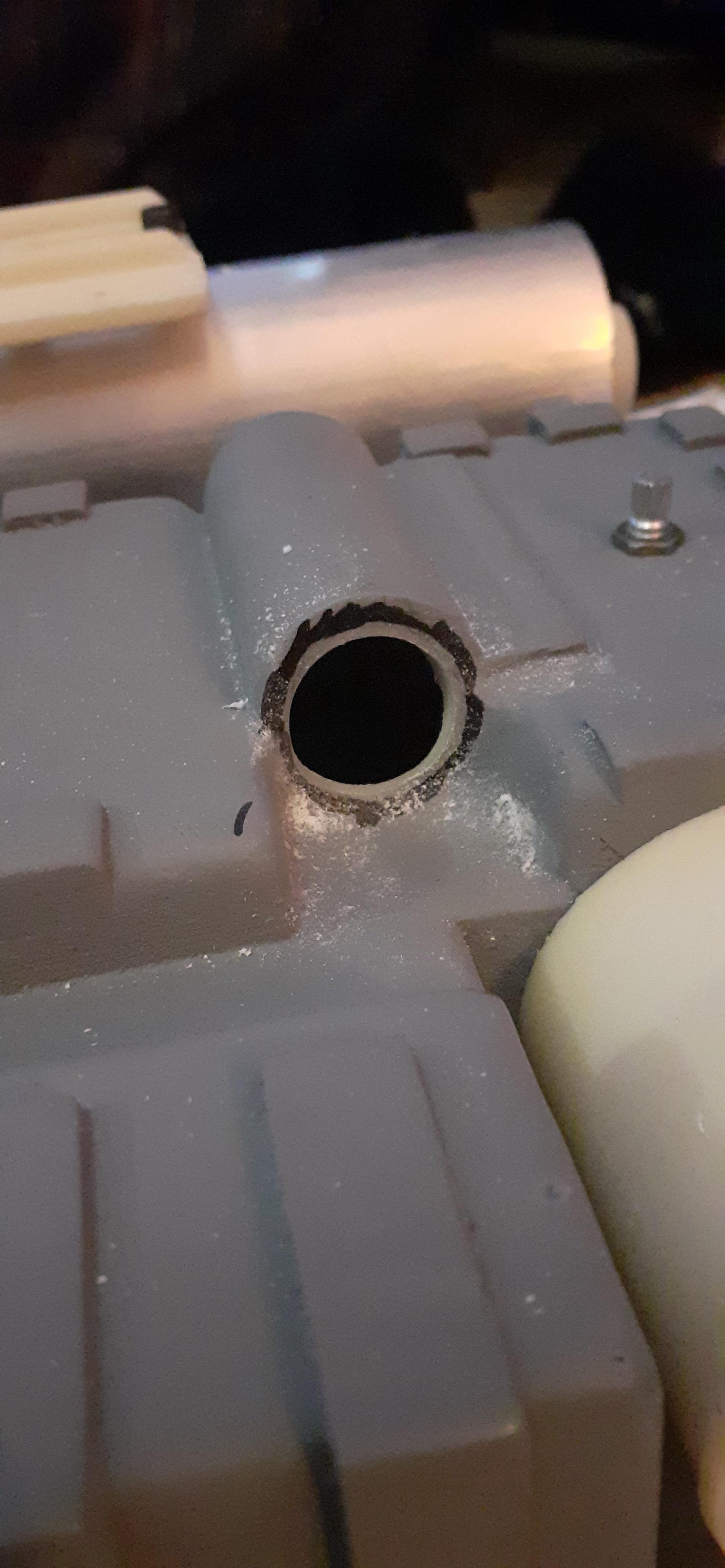
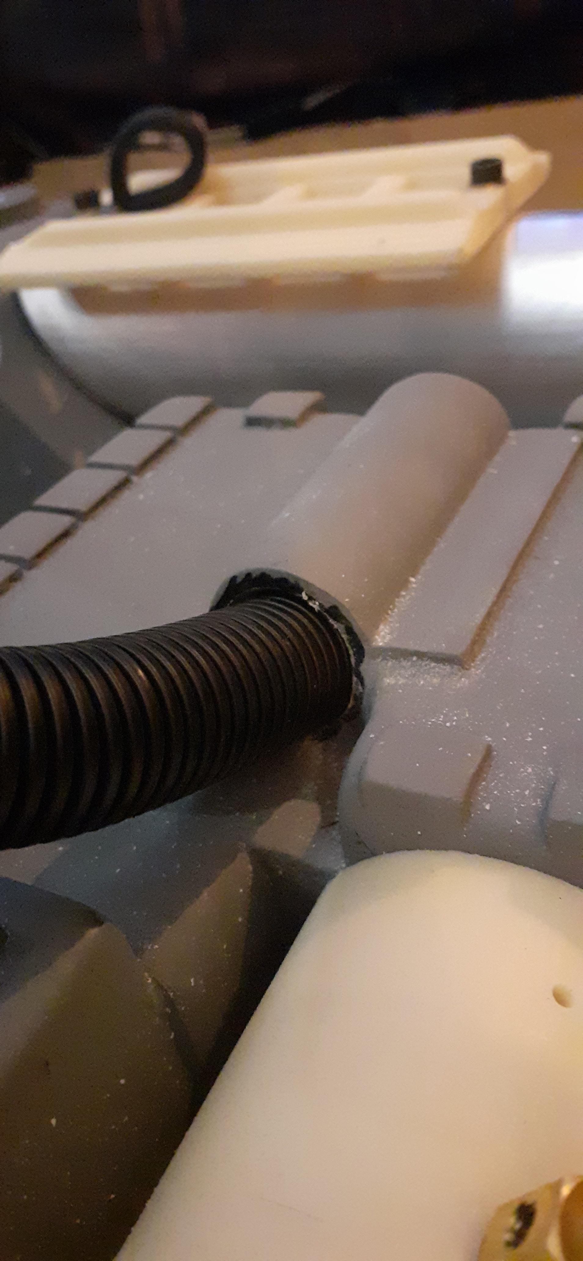
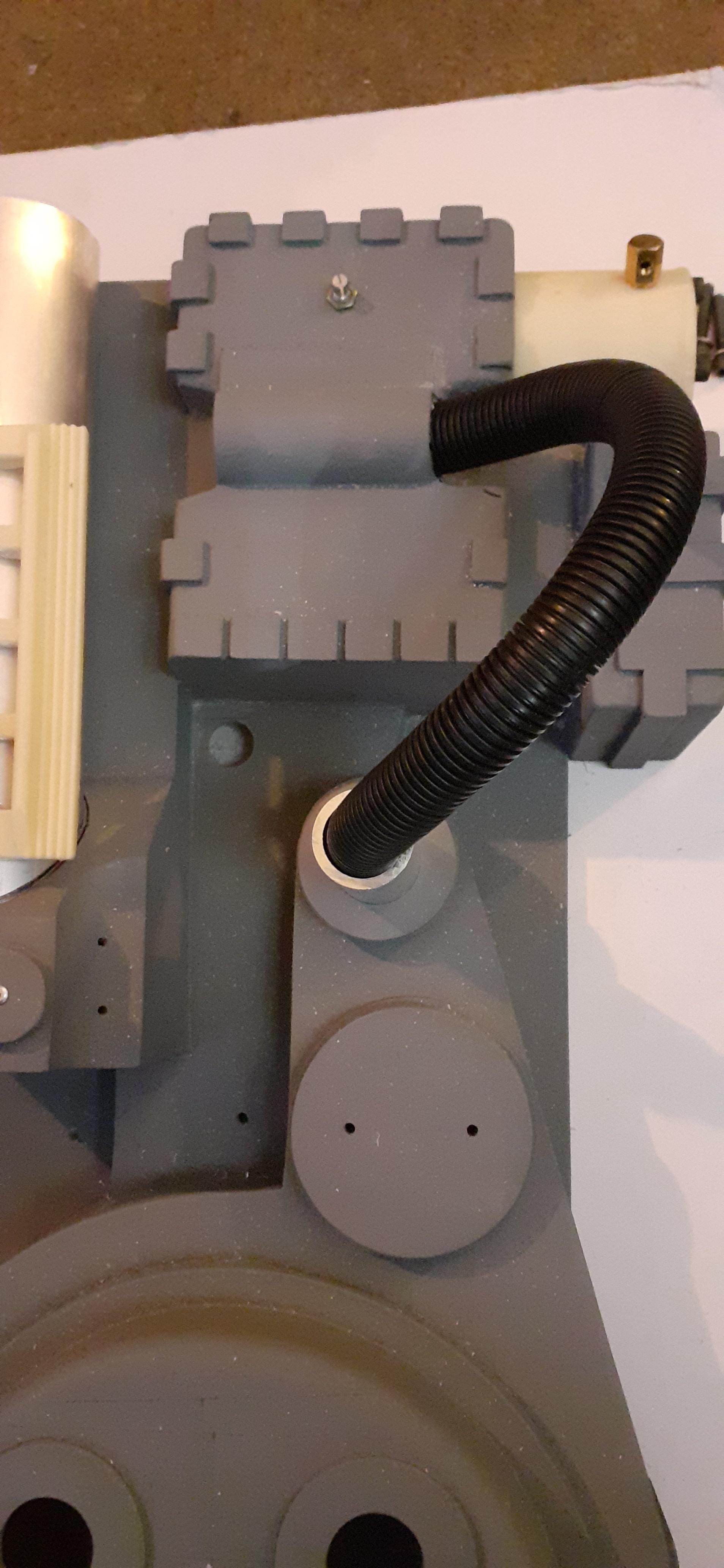
I finally worked up the courage to tackle the hole in the crank generator for the vacuum hose, and it went pretty well, using a 7/8" (22mm) to cut a smaller hole in case of a flub-up and then filing the rest to the diameter of the hose.
I also filed down the vacuum tube to fit into the shell and roughly chopped the split loom for a rough fit, I’ll still need to get a dowel for the crank side of the tube.
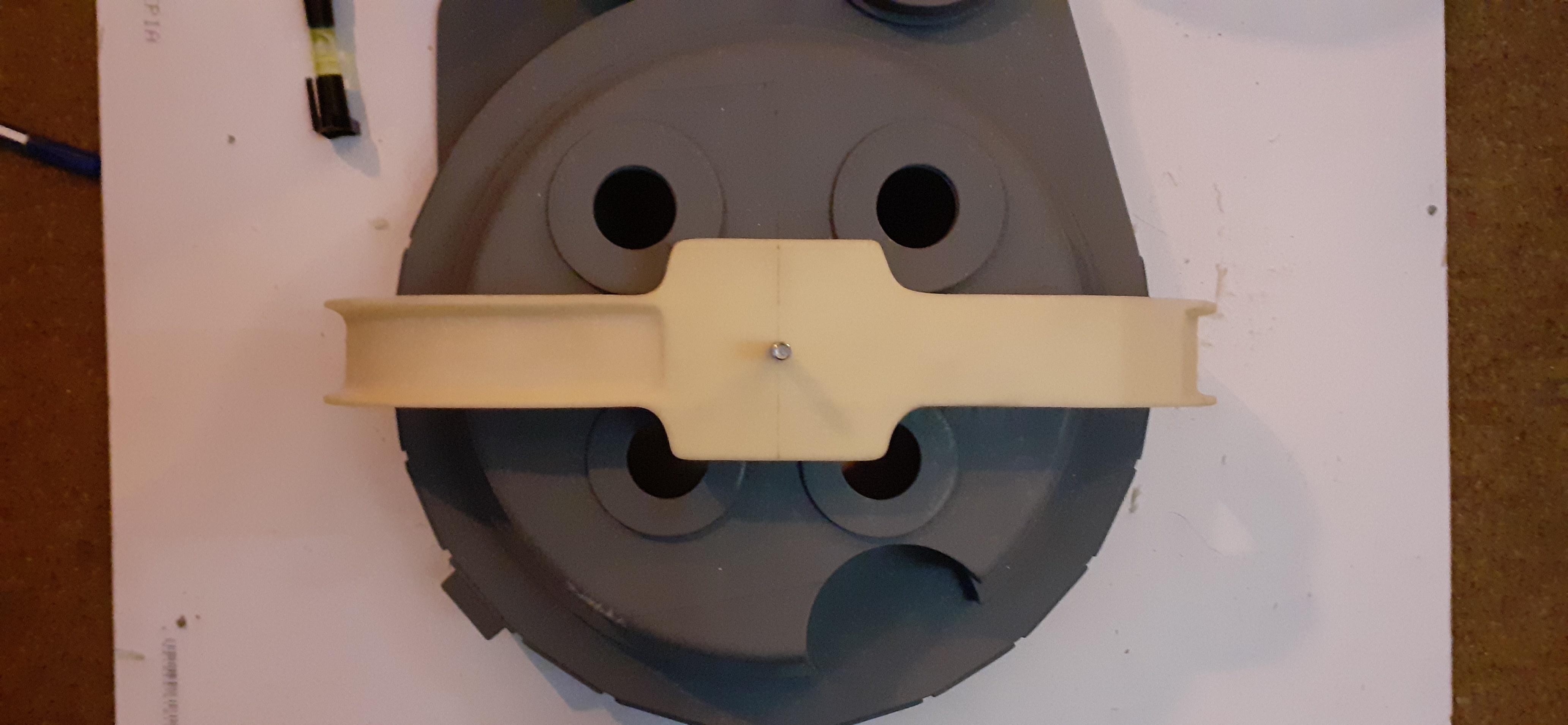
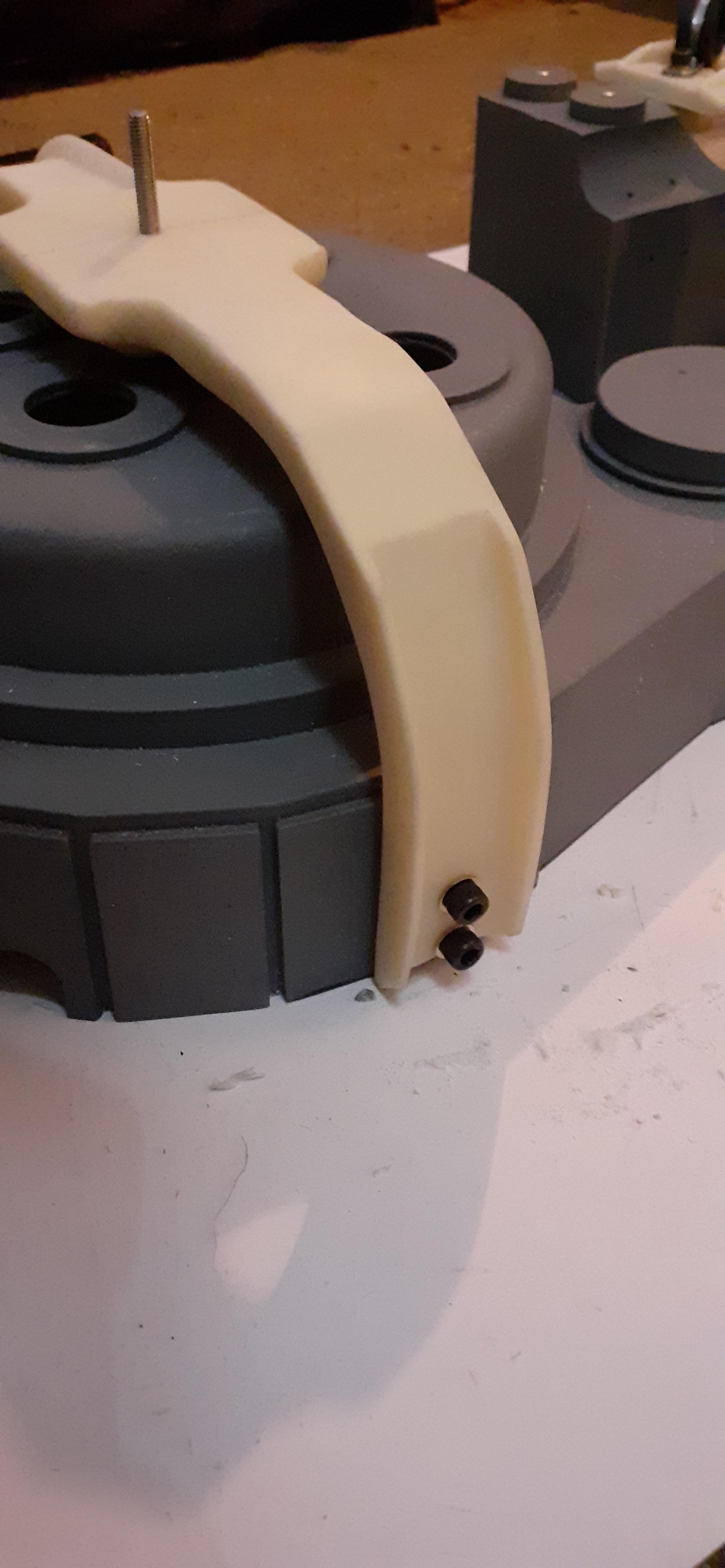
Then I moved onto the bumper, I had already located the centre of the cyclotron and drilled that clearance hole for the bolt and marked out and drilled the holes on the centre and sides of the bumper ( which i forgot to take any pics of)
Then came the joy of going back and forth between making sure the bumper was level on every axis as well as lining the holes up between the side plates. Eventually I got there and drilled the holes I marked first with a pilot hole as I learned that lesson the hard way on a previous drill attempt, then with a 6.5mm bit for the m6 bolts…
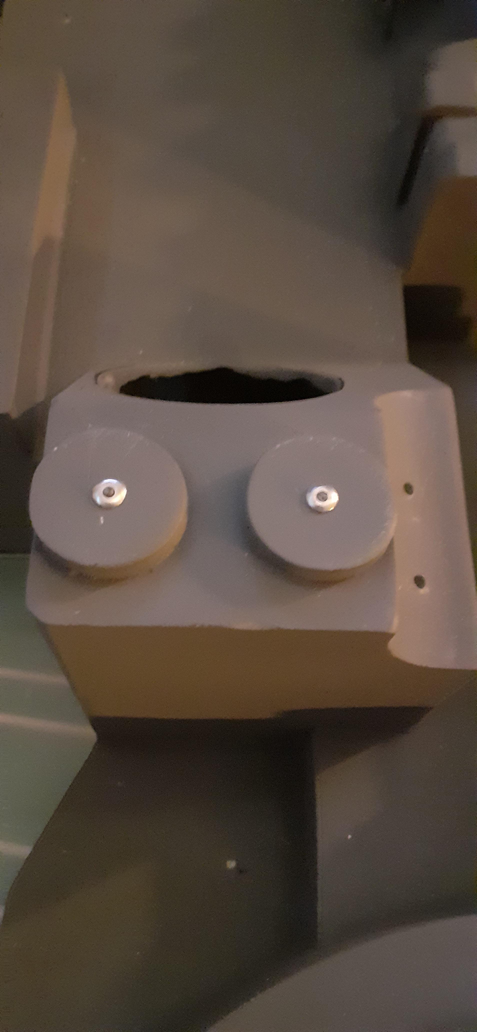
Can the self drilling roofing screws for the beam line, filler plug and injectors be dry fitted then removed and reinstalled after painting and still have a sturdy thread or is it best to only do it the once after painting?
Depending on material thickness (thicker = better) you should get away with it, so long as you make sure you screw back into the existing thread and don’t cut another one, which would loose strength. If you’re able to start the screw with your fingers you should be able to feel when it’s ‘right’ before tightening properly with a screwdriver.
Yeah that’s tricky - sorry, didn’t realise it was into resin, had alu box section in my head for no good reason lol
So long as you’re ultra careful to start the screw in the thread properly, I think you should still be able to get away with it. Or make life easier and simply try cutting the tips off the screws… Might even come off with a big pair of side cutters.
If you never (and I mean, NEVER), intend to take them back out again, you could pop a small amount of epoxy on the screw before putting it back in. That way if it does cut a new thread it should hopefully backfill the old one and put some strength back into the area. However I’d say this is generally a bad idea and/or last resort, as you’d likely destroy things if you ever wanted to remove them.