The board I had access to did not use the light kit, the vent sound was triggered by a single pole switch on his custom hybrid gun
connected to PU4 as you asked about earlier. The DPDT switch replaced that switch. I’ve got all 3 of the new boards on order, so hopefully I’ll be able to adapt the circuit more clearly after playing with them. Whatever switch you are currently using now to trigger the vent sound is where you would need to try to adapt this circuit, I’m assuming it’s a push button on the ear from what I gather from the documentation on the gbfans for sale page. If the dip switch on the sound board for the vent is not inverted, then you could get by with a double pole single throw push button in its place. I am waiting for my boards to arrive to verify if there have been any changes to the new version board to allow for more automatic sequencing of the vent effect without manually flipping a switch or pushing a button
hope this helps, some real schematics on the gbfans boards would really help. I watched some youtube videos of these boards installed that dated 4 to 6 months ago and they were impressive, changing colors on the cyclotron led’s among other effects, and flashing a strobe in the nfilter after an overheat/overload sequence
Here’s some close-up pics of a standard e-cig set up all wired up with a manual push button trigger (in use with a sound borad, this would be connected to a relay that works of the board vent signal or spliced in with a manual vent toggle switch).
Connect your battery pack (11.1v 2200mAH with charging port installed for this set up) to the toggle switch.
The toggle switch is then connected to 12v fan and the 12v strobe LED running in parallel (LED mounted on the inside of the PVC bushing and glued on top of a small bit of wood attached to the center of the fan).
The toggle switch is also fed to the UBEC regulkator that reduces the voltage to 5v (can be switched to 6v by moving the jumper).
The UBEC regulator is then wired out to the air pump and e-cig cartomizer.
The cartomizer has the positive red wire carefully soldered to the center pin and the ground black wire is soldered on the outside with a grove cut to allow this wire to be soldered flat on it (see reference pics earlier in this thread). These wires are fed through the 2 existing air-holes with 1 made slight larger to accommodate the red wire more easily.
CAUTION: When soldering the red wire to the center pin, DO NOT ALLOW solder to plug up the center hole. This procedure requires high heat to adhere the wire to the metal center pin; it helps to scrape off the coating and to use Flux wax to help the solder adhere.
The vacuum plug fits snugly inside the K2 cartomizer end. The tubing is fed through small hole that allows for an air-tight seal and the other end of the tubing connects to the air pump.
If connecting to a soundboard vent toggle switch, you will use a double pole, single throw (DPST) toggle and wire it to the existing leads from the red trigger switch seen in the pics above. If the soundboard you are using has a digitally coded low-level signal (4-5v) during the duration of the vent sequence, then you will need a relay brick (not shown here, converts low-level voltage to 12v) that can accept that signal and act as the trigger for the on/off switch.
If desired, a manual “kill-switch” (not shown here) can be spliced onto the battery wires.
Notes:
If you connect the cartomizer directly to 11.1v supply, it will burn out the heating coil, the UBEC switch is essential to keep the voltage at 5v or 6v.
The cartomizer works best when pointed down or at and angle.
Fantastic! It still looks a bit daunting for me (electronics illiterate) but I am going to study your instructions, this post has motivated me to at least try this project. Thank you very much for your effort in sharing this!
First off - this is a really amazing system and idea. Well done to all involved!
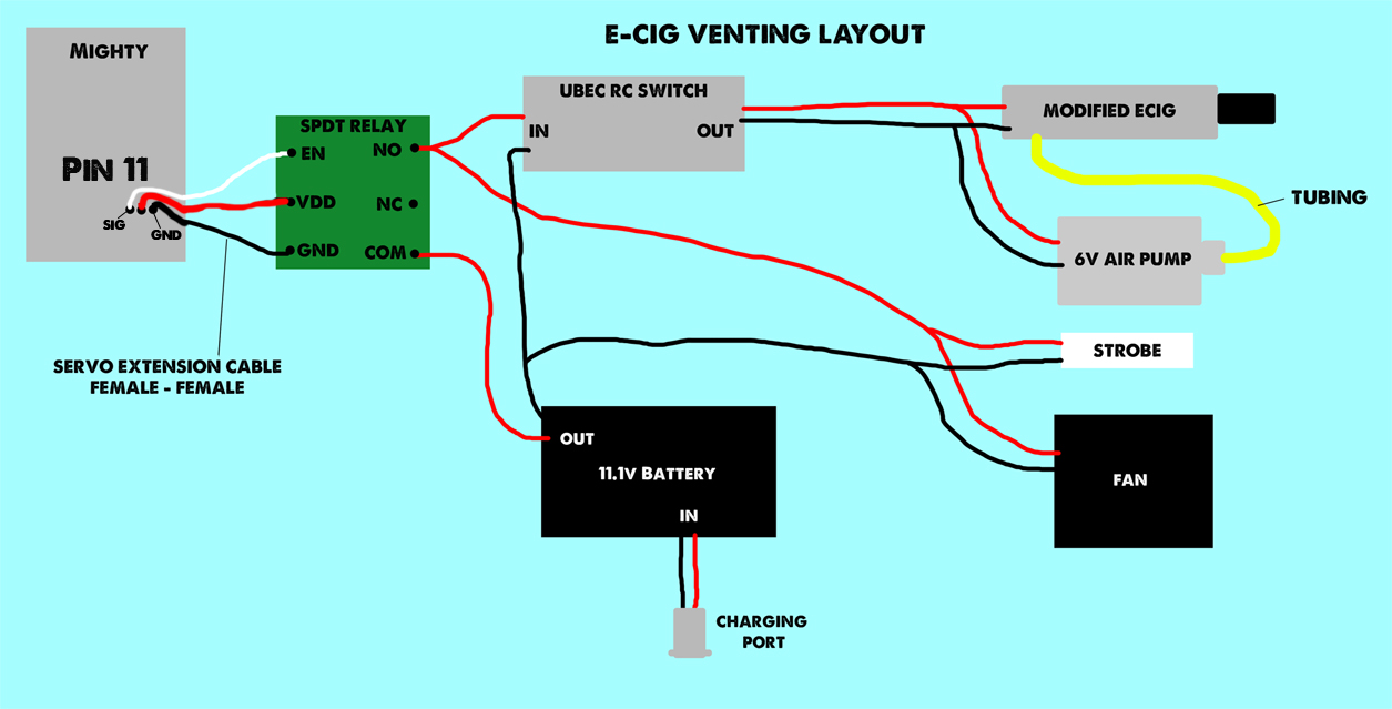
I was able to toss together a quick visual layout for the wiring, for those who aren’t schematically inclined. This drawing is for use with the Mighty microcontroller, which is what I have in my pack. Your mileage may vary.
Great call on the pololu site, I used the 12V relay because I couldn’t find a 5V brick rated at more than 1A. Thanks for the post,
makes the wiring even simpler.
Also after some research I have concluded the same relay may be wired in parallel to the 5th LED output from the gbfans cyclotron light board which blinks in sync with the vent sound if i’m reading the documentation right. The 5V to VDD center pin on the input would have to come from somewhere else since the led output might not have enough Amps for the relay coil, the relay brick I’m utilizing lights up an opto coupled led on the brick to activate the relay coil. The smoke would pulse rather than be constant since this signal blinks the LED. I’m waiting for my boards to play with so I can see if this signal can be modified to give a constant voltage, otherwise the intermittent smoke looks ok but not quite as effective as in the video. Perhaps a latching relay tied to a timer delayed shutoff, will try to upload a video showing the intermittent smoke and keep working on a solution for a constant trigger signal
Really hope you find a solution because i’d do it with the new gbfans kit too. Im sure AJ said the autovent feature may be included on this set of soundboards
Maybe a trigger from all 4 cyclotron lights being lit at the same time (which only happens during the overload sequence)? Timing will be a little off, but it’s an option, I guess… My electronics theory is a little rusty right now, but maybe an AND Gate that only switches on when all inputs are active? And maybe a timer that allows it to trigger at the end at the overload sequence? Again, I’m rusty, but it’s making sense in my head right about now… =P