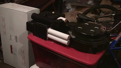
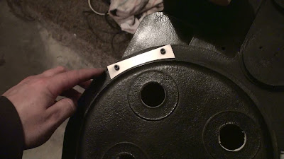
Gush's Humbly Endeavoring Proton Pack Build

I decided to finally start a proton pack build thread. I’ve been lurking for awhile and haven’t had time (or confidence) to really start sharing my experience, so hopefully my fellow Ghostheads can forgive me. :slight_smile:

I built a proton pack back when I was a kid, around the time the movie came out in '84. The only reference I had was from a behind-the-scenes broadcast (VH1?) that we recorded on VHS. For what I had to work with, it turned out great (actually it was pretty bad, but don’t tell my younger self). But I always wanted to try and build something better and more accurate. Finally, 30 years later, I made a promise to myself to finally give it a go.

I’m extremely intimidated by what I see here. You guys appear as GODS when it comes to building packs. So my attempt may not even come close, but I’m gonna try anyway. I am not shooting for 100% accuracy and I’m taking a few shortcuts to keep the budget in check. I hope that doesn’t disappoint anyone, and sorry if anything I do makes you cringe. Feel free to laugh at me and criticize all you want…(on second thought, just sing to me and say supportive nurturing things. :wink: )

Alright, enough introductions and disclaimers. I started collecting parts and building in February, so I’ll start sharing some photos (or “pack ■■■■” as y’all call it) of my progress in posts to come.
A couple of tips for the new builder:

  1. If it helps with how intimidating the whole Pack appears, trying looking at it as its component parts, rather than the whole.

  2. If money is an issue, you don’t have to buy everything at once. Parts come into and out of stock across the year, so the whole caboodle is never always available at one time. Spacing the purchases out will allow you to save up extra cash to help you get more of those bits you want, but might not be able to afford if you bought them all together.
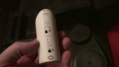
:slight_smile:

Thanks for the tips! Through the process I’ve learned that #1 is especially true. When that pack is put together it looks really impressive (and intimidating), but all that it really is, is a bunch of little parts assembled by going through a bunch of little steps.
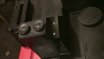
Like I said, I’ve already been working on this since February, so I’m not sure where to start in sharing. In order to keep costs down I decided to try and build most of my own parts despite the excellent crafters here selling them. I would try to scratch build what I could without spending any money, or as little as possible using materials I already had or what I could find.

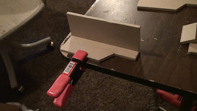
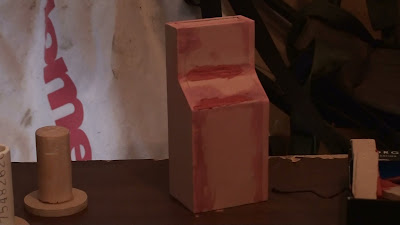
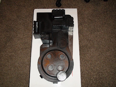
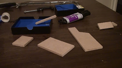
My favorite part that I built was the Ion Arm. I used Stefan’s plans to measure and cut the sides out of 1/4" MDF board.

image

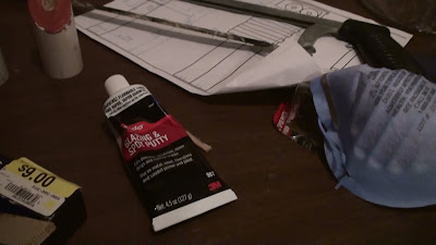
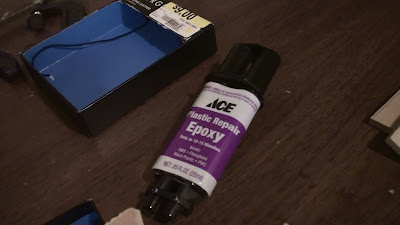
Used this stuff to glue it together. It says plastic, but works great for other materials too.

image

Clamping together.

image

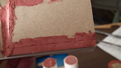
And everyone’s favorite putty to fill in the cracks.

image

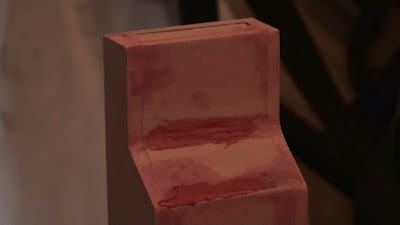
It took several layers of that putty and a lot of sanding.

image

image

image

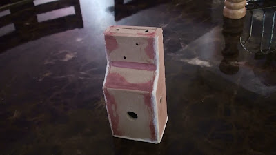
Drilled the holes and added a fake weld with some acryllic/silicon caulk and came up with something like this:

image

Ion Arm looks great, bud! Keep it up!

Thanks, you’re too kind. :slight_smile:

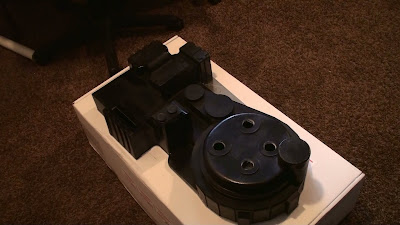
I was happy when my end cap (from GBFans shop) was delivered and it was a perfect fit! It assured me that I had at least done one thing right.

image

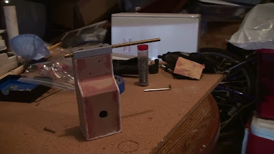
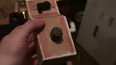
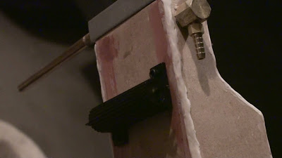
Here’s progress in attaching the parts (also from GBFans shop) to the Ion Arm for a dry test fit:

image

image

image

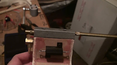
This painted resin resister below is from Jack Doud. I like that it matches the other one that is of the Sage style, but I personally like the style of the Dale resistors better. Maybe I’ll switch in a future update.

image

Dale is technically screen accurate for the bigger resistor but when I build my next one I’ll be using the same style as you have. It’s really looking good!

Nice start on the Ion Arm! :slight_smile:

Only the Venkman, Stantz, and Super Hero Packs have the longer Dale resistor; the Spengler and Omni Packs actually have the Sage.

I knew that the longer Sage was on some screen packs, but I’m not going to be 100% accurate on everything due to budget constraints, newbieness and personal preference. That’s not to say I won’t do my best to try and make it look good though.

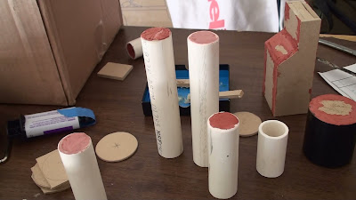
As a part of trying to save money on this build where I can, I started to approach this with a simple-minded point-of-view. What IS a filler tube, beam-line, booster tube, HGA, Ion arm, end cap, etc. They are just shapes, right? Cylinders, tubes, boxes, rods. Simple stuff you see everyday. So as dollar store pack builders do, I started looking around for stuff that is close in measurement that is shaped like the part I needed and modified it to make it look somewhat convincing. I grabbed some PVC pipe that I had, and a trip to Home Depot for some other inexpensive materials.

But here’s something I learned that you experienced builders will likely smack your foreheads at. Being 1/8" off or even 1/16" off in size on certain parts can make a significant difference in how things look when it’s all assembled. I thought I could get away with it, but ultimately I wasn’t completely satisfied with all of my results. I’ll demonstrate that later, but for now here is my homemade HGA.

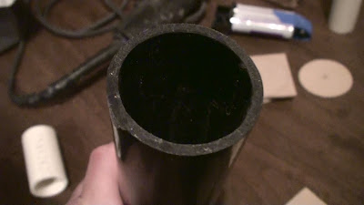
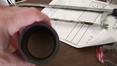
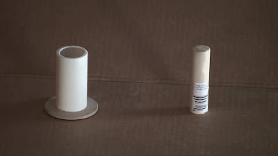
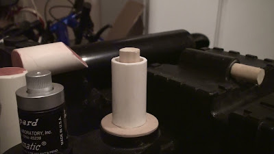
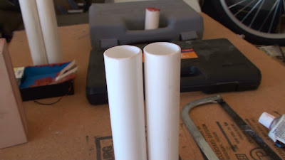
Started with a tube like this:

image

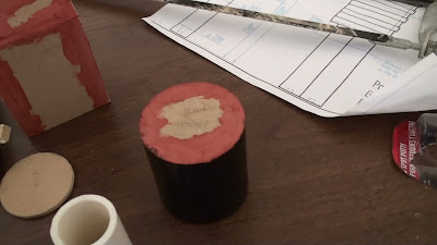
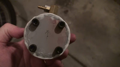
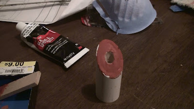
I cut it to size and then cut some circles out of 1/4" MDF (you can see one in the background above) sized to the inner diameter of the tube, for the top and bottom of the HGA.

image

Used the Bondo spot putty to fill in the small gaps and smooth out the surface:

image

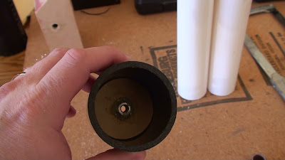
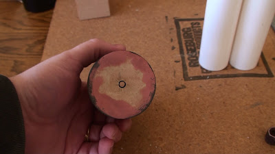
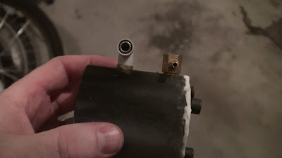
Drilled a hole in the bottom and epoxied a nut inside for more secure mounting (whether that is necessary or effective I don’t know, I just thought I’d try it):

image

image

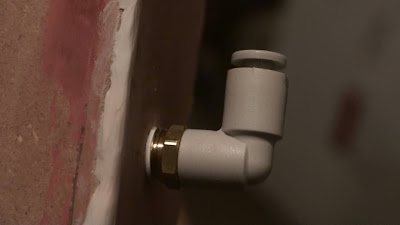
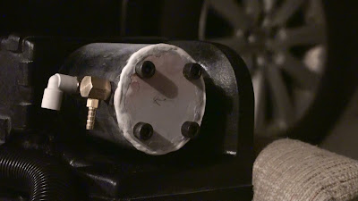
Then I guess I forgot to take pictures for awhile as I can’t find any…but I put the top on, putty and sanded, measured for the hex-screws, added a fake weld, drilled and tapped for the elbow fittings, and ended up with something like this:

image

image

The gray primer in the top picture was just a test spray as I wasn’t sure if and how much I needed to sand the body so any scratches would not show. Turns out that primer covered it quite well so I didn’t need to sand much at all on this part before priming and painting.

Huh, I thought it was added after filming for the omni pack. Whoops

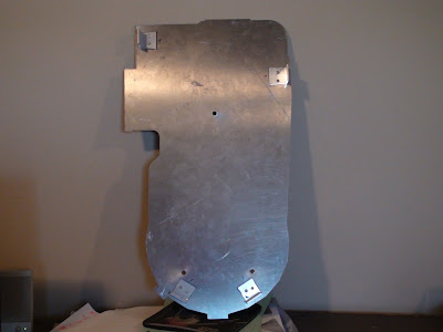
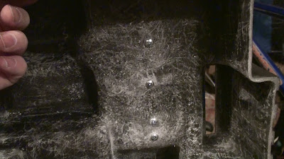
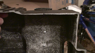
When deciding on a shell, early on I considered a full scratch build. While this would certainly be inexpensive, I doubted my abilities (and time) would deliver the quality I was hoping for. I came really close to getting a StudioCreations shell, but I knew that I wouldn’t be completely satisfied with it as the detail on it does not quite match the fiberglass ones. So I splurged and got a GBFans shell, and figured while I was at it I’d get the aluminum motherboard as well.

image

image

It was a bittersweet day when this arrived. I was extremely excited and awed at this marvelous thing I had just purchased, and I started to question my sanity. But my excitement quickly turned to grief as only minutes later that I would learn that Harold Ramis had passed away. Needless to say, It was a very significant moment in my pack building adventure, and I realized that I MUST complete this. If not for myself, then for Egon Spengler!

I was going to show the process of mounting the motherboard to the shell, but I pretty much followed exactly the method outlined in kind2311’s how-to thread, so there’s nothing new to mention, other than I never used a rivet gun or drilled through metal before this project.

Mounting looks like this:

image

image

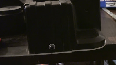
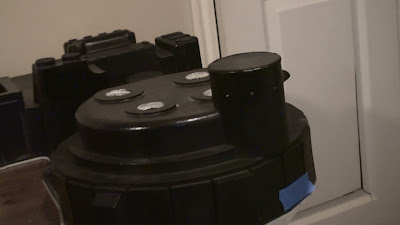
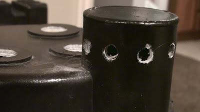
As you probably have seen, the GBFans shell comes with a lot of spots marked on where to drill holes, like on the N-filter shown here:

image

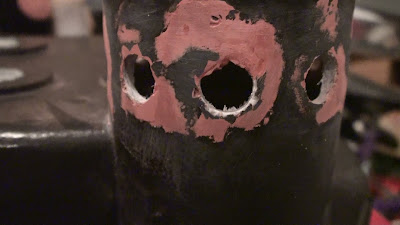
Now I had prepared myself for drilling out the N-filter holes by reading up here on the forums. I had seen what happened to NoodleMaps’ N-filter, and I drilled with some advice that folks gave: drill slow, and start with a smaller bit first and work up to the final 1/2" bit.

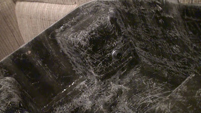
Well, I tried that and I think mine looked just like his after my failed attempt:

image

I later discovered that reverse drilling or possibly a forstner bit would have prevented the gel coat from chipping and given me nice, clean holes.

I was pretty upset about this, so I just grabbed that Bondo spot putty and tried to fix it the best I could.

image

I had to do several layers and sand it. I don’t recommend using that Bondo spot putty for fixing stuff like this. It’s not easy to mold and it tends to crumble on the edges. I believe it’s more for smoothing out surfaces. I’d recommend just drilling it differently to avoid the problem in the first place. But if you happen to screw it up like me, I’d use some plumber’s epoxy putty or some other kind of filler epoxy to fix it, similar to how n0c00lgamertag did it for his.

Back to parts!

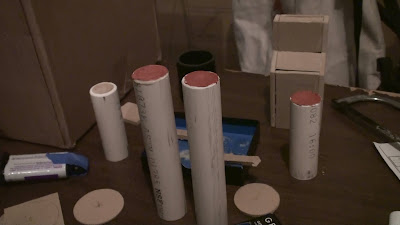
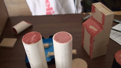
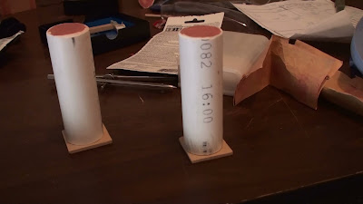
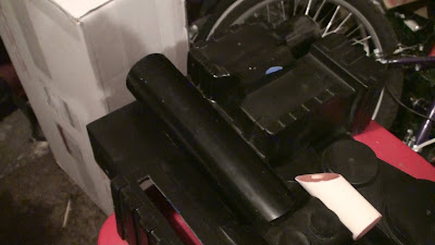
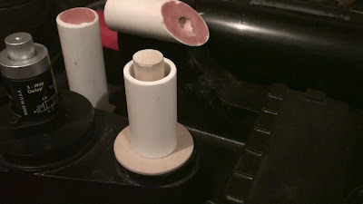
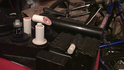
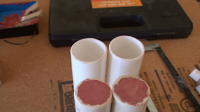
I started with some 1" (ID) PVC pipe that I already had and cut it to the appropriate lengths. This would make up the PPD, filler tube, beam-line, injectors and vacuum line. I cut a 1" wooden dowel to epoxy inside each pipe and then spread that wonderful Bondo spot putty on the tops and sanded them to smooth 'em out.

image

image

I drilled a 1/4" hole in the PPD for the split loom/blue tube to fit into later.

Started sanding the tops nice and smooth here:

image

image

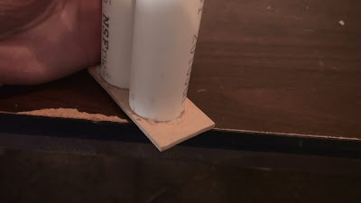
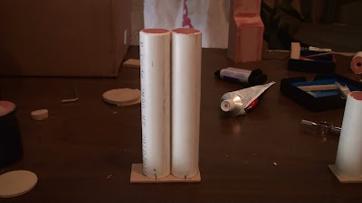
And glued some bases on them cut from 1/8" MDF board:

image

image

image

The vacuum line I planned to use a 3/4" wooden dowel mounted inside to hold the wire loom in place (which I will show later). I couldn’t get the darn UPC sticker off, but it’ll be inside the loom anyway, so it won’t show:

image

All parts will be mounted with screws from the inside for easy removal should I ever need or desire to replace them. This would prove a wise decision as I soon realized as I started to test-mount these parts, it became apparent that they were not the right size. Parts like the filler tube and beam line simply looked too big on the pack, while the injectors were too small. I really thought they would be within an acceptable size margin. Of course the parts would work just fine…I mean, we are talking like a fraction of an inch here, and the average Joe isn’t going to know the difference…but…well…I simply wasn’t happy with the way they looked and I’d have to replace them. Unfortunately I don’t have a shot of that. I was probably too embarrassed or frustrated to capture that disappointing moment.

:sigh:

You’re going to end up with a fine example of a proton pack project, I am sure. Your accuracy standards already are at the fraction of an inch. :slight_smile: If you’re not shooting for 100% accuracy, you’re aiming close. Keep it up.

A round file will clean those holes right up! Everything else is looking great so far! :mrgreen:

Thanks for your thoughts and encouragement, fellas! I’m probably my own worst critic!

Here I started drilling holes for the various parts to test mount them to make sure everything looks good and fits right.

PPD

First I drilled two holes in the shell:

image

I initially taped the PPD on and drilled up through the holes underneath and into the back of the PPD. The result was some matching holes for the screws:

image

Started the screws just enough to poke through in order to line up the PPD:

image

image

image

And ultimately the screws would be tightened and the PPD is mounted.

Booster Tube:

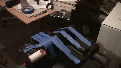
The booster tube was mounted in a similar manner, though I thought I’d try something different by drilling the mounting holes through the back of the shell and directly into the tube. I probably should have measured and drilled the initial holes through the front first similar to how I did the PPD as that would have been more precise. But I did it by taping the booster tube down with whatever tape I had within reach to hold it in place while I drilled through the shell and the tube walls. The crappy painter’s tape wasn’t very sticky so I had to use quite a bit:

image

Drilled the holes and put some screws in there for a test fit:

image

As you can see, I rushed this and I probably should have spent more time making the screws all line up straight, but I think I’m okay since the general public won’t see this part. I also forgot the washers here, but I’ll be removing the booster later anyway to paint, so I’ll add them then.

I made sure the booster tube extends 1/8" above the top per the plans. These types of accurate details are simple, so I make sure to implement stuff like this where I can:

image

And mounted:

image

Continuing to test-mount parts:

image

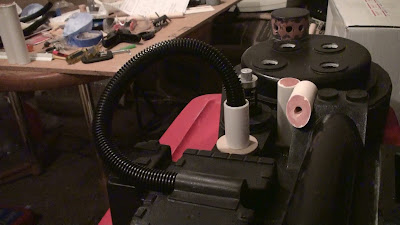
You’ll notice from this picture I’ve got the PPD, beam-line, clippard valve and vacuum line mounted.

I mounted the replica clippard valve (from Wiz-GB008) with two 8-32 cap head screws, with nuts on the inside to hold it on:

image

To the right of the clippard screws in the photo is a screw that is holding the beam-line on.

Vacuum Line/Tube

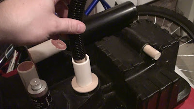
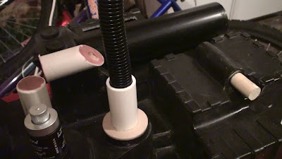
Here’s how I attached the vacuum tube. I used a 3/4" dowel inserted into the center of the PVC pipe which was glued to a disc base made from 1/8" MDF board. I drilled a hole through the bottom of the shell and through the disc base and into the 3/4" dowel, which acts as a nut of sorts. That holds the whole vacuum line assembly on.

image

image

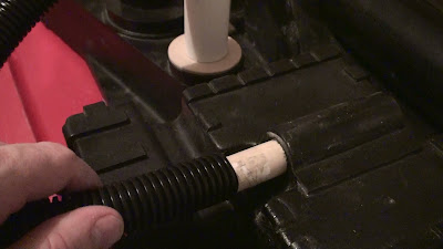
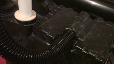
Rather than drill a hole into the gear box for the wire loom vacuum tube, I liked the idea someone suggested here to just use a small length of 3/4" dowel to attach the wire loom to, which still gives the effect of it going inside. I drilled a small hole for a screw and screwed it into the dowel from inside the shell:

image

image

After that, it was really easy and simple to attach the wire loom using this method:

image

image

image

image

image

The wire loom looked a little long so I ended up trimming it down later. And later I cut the dowel to the crank gen in half, as I felt it made the loom too straight coming out of the box. I also put a little tape around the dowel so that it was a tighter fit.

I really like attaching things without using glue! :slight_smile:

HGA

HGA is mounted with a single 1/4" 20 cap head screw. I tapped the MDF bottom and epoxied a nut inside (as previously shown). The hole I drilled into the shell was already marked with an indentation similar to others on the shell. (Some of these are actually earlier pictures without the elbows attached.)

image

image

image

image

This is one of those parts that is just a little off in size. I will probably replace the HGA eventually, but I sure had fun making it. :slight_smile:

Injectors

I mentioned before that I had the wrong sizes for some of my home-made parts. The most apparent were the injectors. I had used 1" PVC pipe, which has an outer diameter of about 1 5/16". The correct size for these is 1 1/2" OD according to Stefan’s plans and other sources. While I was aware of this, I thought that the PVC pipe would be close enough, but it was surprisingly obvious that the whole assembly was too small when I started to test-mount it to the shell.

So I went out and found some cheap plastic plumbing pipe from Home Depot with the proper OD of 1 1/2", cut two pieces to the proper length, and began crafting my new injectors.

image

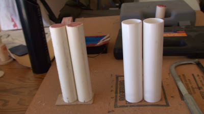
Here are a couple of comparison shots for the old vs. new. See what I mean?

image

image

Also, instead of plugging them up with a dowel like I did with the PVC version, I just added MDF disc plugs in the top and bottom similar to how I did the HGA. The advantage of this is that they weigh a heck of a lot less since they are now hollow. My aging back should appreciate that when it’s done.

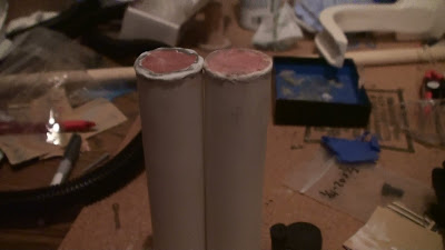
Here’s a shot of the tops (er, bottoms technically) with them puttied and sanded and fake weld added:

image

I originally tried using that grey plumber’s repair putty that everyone likes for a fake weld, but I just couldn’t achieve something that looked good, so I ended up using the same acrylic/silicon caulk which seemed to work well on my other parts.

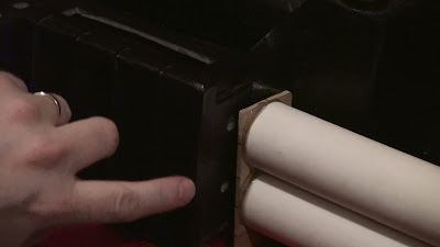
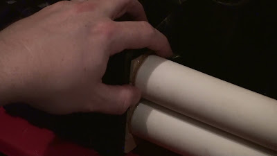
I epoxied a 1/8" MDF base to the bottom (or the top depending on your perspective), tapped some holes, measured and test-mounted the assembly to the shell using 1/4"-20 screws from the inside:

image

image

image

Now some might think this was a pain to have to re-do, but honestly I had a great time building and re-building these. I don’t consider any of it work. It’s all really fun for me. :smiley:

Ribbon Cable Clamp

I put the ribbon cable clamp (from GBFans shop) on sometime during this timespan for a test fit as well. I didn’t recall seeing any measurements for it (though I really didn’t look very hard), so I just eyeballed it. It looks like it’s in the right spot.

image