Filler Tube and Beam Line
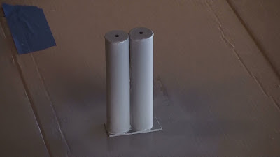
Another couple of parts that I realized were too big, were the filler tube and beam line. Again, this 1" PVC pipe has an OD of 1 5/16", whereas Stefan’s plans show 1 3/8" OD for these two parts. Honestly I probably could have let this slide, but I went ahead and ordered a 1 3/8" OD polycarbonate tube, cut two sections of equal length, epoxied in those special 1/4" MDF disc plugs for the tops and bottoms, attached to a 1/8" base, and I had my new parts in no time.
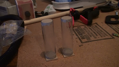
And for a size comparison, old vs. new:
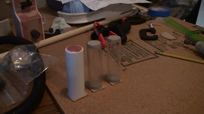
Beam line tapped for the elbow:
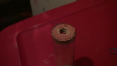
And both parts test-mounted with a 1/4-20 screw through the back of the shell:
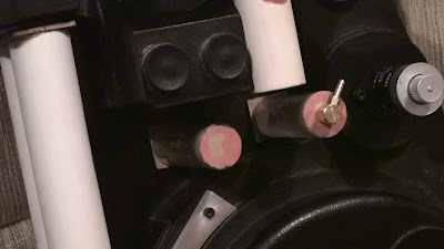
I think the smaller size looks a lot better on the pack.
Legris Straight Fittings
Drilled holes for the legris straight fittings (from GBFans). I started with a smaller bit and worked my way up, but this time I did reverse drilling so the gel coat wouldn’t crack.
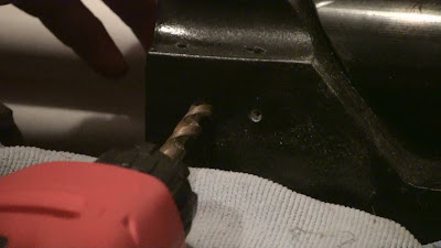
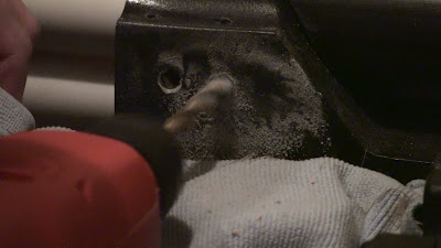
Then I tapped the holes so I could just screw the straights right into the shell.
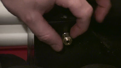
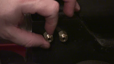
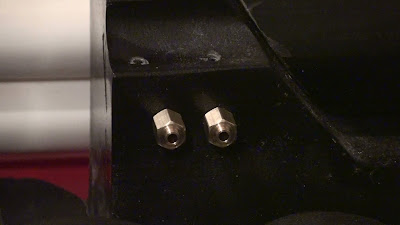
I thought about adding a nut on the backs of these, but these are really tight so I don’t think it’ll be necessary.
SMC Elbow (Cyclotron)
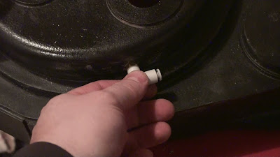
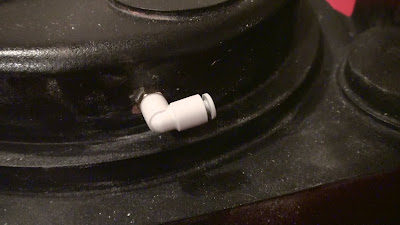
For the elbow on the cyclotron, I drilled and then tapped it with the appropriate thread size, however it’s difficult to screw it in because the elbow end bumps into the base on the cyclotron while tightening it. I managed to get it in somehow, but this may be a part that just needs a bigger hole with a nut to hold it on.
Ion Arm
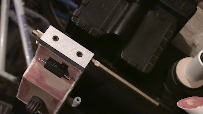
I didn’t have too many pictures test-mounting of the Ion Arm. I had a little bit of difficulty as the shell is a little warped in that spot, but ultimately it worked out. I used 4 1/4"-20 screws to mount it from the inside, and into the bottom of the Ion Arm, which was just 1/4" MDF board like the rest of the part. I added a layer of epoxy on the bottom panel to strengthen it, let it dry, and then tapped the appropriate holes.
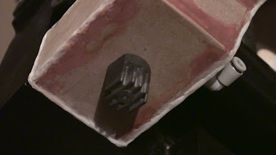
Booster Plug
This was just a dowel cut to length, sanded, and then epoxied to a 1/4" MDF disc base. I tested the paint I just bought on this part before I did any others just to see how well it would coat.
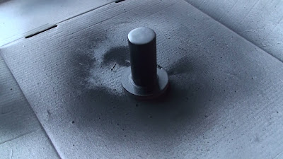
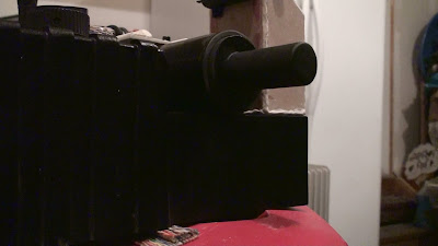
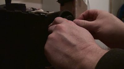
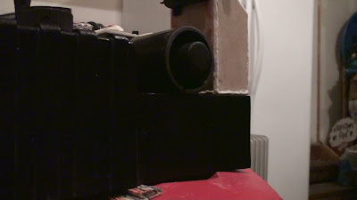
This was just loosely inserted into the booster tube. I later measured the cylinder extending from the tube to adjust the position and used some Loctite epoxy to permanently attach this inside.
Booster Frame/Crank Knob
I got in a hurry and forgot to take pictures of test-mounting of the booster frame (from KCGhostbuster) and crank knob (from Jack Doud), but here is a partial shot of those
mounted:
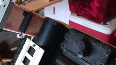
I didn’t do anything special with the crank knob. I didn’t really want it to control anything because I fear kids or immature people will turn it to see what it does (Ooh! Maybe I should add a booby trap to it so when they do touch it, it shoots slime at them or something! :twisted: ) But it is just attached with a 1/4" screw from the inside and tightened so it doesn’t turn.
Ribbon Cable
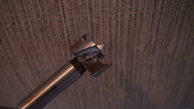
I didn’t capture the moment when I drilled the hole for the ribbon cable, though I wish I would have. It was the cleanest hole I made in the shell! As advised by some here on the forums, I scraped together some cash and bought a cheap set of Forstner bits. These are awesome for drilling through the shell! Wish I had them to begin with. :roll:
I made a couple of small holes in the ribbon cable (from GBFans) to attach inside the aluminum hold down:
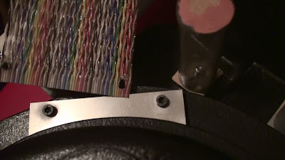
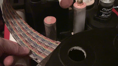
Then I just put that in the middle with the holes lined up, inserted the screws going through the top plate and through the cable into the bottom plate. Nothing terribly complicated here.
I attached the cable clamp to the booster frame and inserted it into the 3/4" hole in the shell:
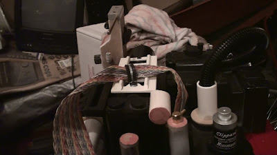
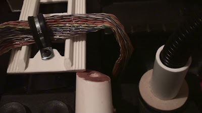
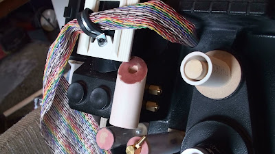
Now I have seen how picky some are about the twist in the ribbon cable. Looking at the reference shots (particularly the Sony Lobby), there didn’t appear to be much twist at all on the GB2 cable from what I could tell. This stuff is actually very rigid so it isn’t easy to shape, but for a test mount I just rolled and bent it to resemble something close to the reference pictures. I realize there is a weird bend in it before it shoots down into the shell. I think I fixed that later since it was bugging me (and probably you too).
Here is a full shot of my pack with most of the important parts test mounted:
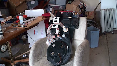
PPD II
It was at this time when finishing up the test mounting that I looked at my PVC PPD and thought it was too big. Darn! It was was close at 1 5/16" OD, but for some reason it just stood out to me among the rest of the parts and I knew it would bug me to death if I didn’t fix it.
So I ordered another polycarbonate tube of the correct outer diameter of 1 1/4", and made a better PPD.
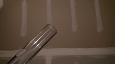
I decided to try some plumbers repair putty to fill in the top and bottom instead of the full dowel with Bondo spot putty. This stuff is much more rigid and easier to work with and can also be sanded to a nice smooth surface when it dries, so I filled that in the top.
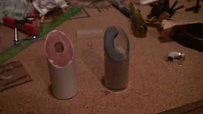
I had this finished in no time, and mounted it the same way I did the previous PPD. I also decided to mount it straight instead of rotated, as I didn’t like the way it was bumping up against the booster frame.
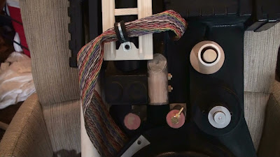
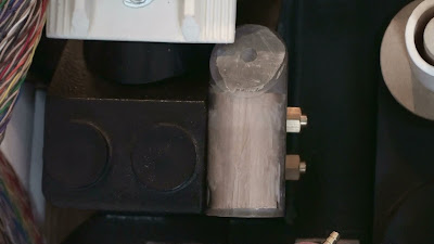
If you notice in the photo, the epoxy I used to secure the wood dowel inside expanded a little when it dried. This created a bunch of little hairline cracks in the tube, but these are only on the inside (thank goodness). The outside is still nice and smooth as it should be.
Bumper
The bumper I got from KCGhostbuster. It comes with nice little indents where to drill the mounting holes. It also comes with the seam which is screen accurate for some packs, but also can be sanded off.
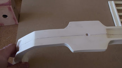
I originally thought the seam was cool and gave it some character, but there was one part that was just a little too uneven for my liking.

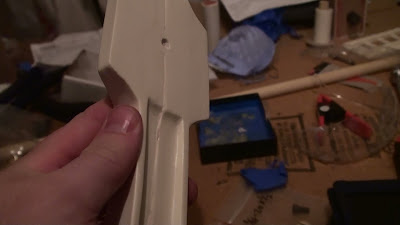
I tried to fix that, but ended up sanding it off too much so I opted for a seamless bumper instead. I used that lovely Bondo putty to smooth it out the best I could.
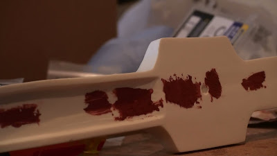
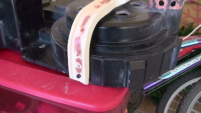
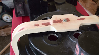
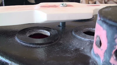
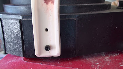
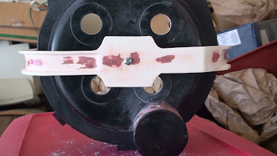
I drilled two holes between the side plates on each side for the screws, and drilled all the marked holes on the bumper. I drilled the center hole based on where the bumper lined up and used a 1/2" steel spacer in between the shell and the bumper. The holes in the bumper aren’t tapped, but drilled to the proper size so the screw just drops through loosely, then fastened with a nut on the inside. The center hole was initially off by about 1/4" due to an eyeball measurement failure, but I drilled it larger and later patched it up. Here I have the center bolt going through the top, but eventually it gets inserted through the bottom into the shock mount.
V-Hook
I pondered making my own v-hook, but I doubted my creativity would give me something good enough. While I think I could have made something look good, but I worried about it being secure enough to hold the wand/ So I ordered this V-hook from Freeky Geeky.
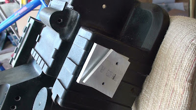
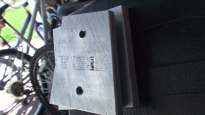
Mounted it with two screws from the inside. The screws are a little short, I think, so I’ll have to get some longer ones.
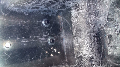
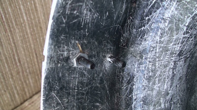
It’s interesting how the sun reveals thin spots in the shell here. It almost looks like there are holes in it, but it’s just thin enough there to let the sunlight blast through.
SMC Elbows
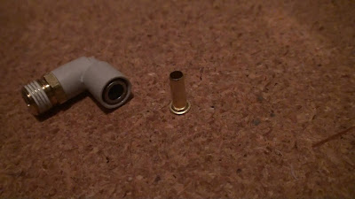
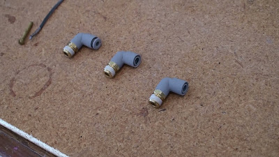
Here’s a little mod I did. I was trying to remove the button end from one of the SMC elbows to see how it was attached and accidentally broke the tube insert that is part of that. So I painted them and bought some little inserts for them and grinded down the little lip on the end and super glued them inside so they kind of look like the old style Legris elbows. I left one with the button end since I believe the Sony Lobby pack has it that way, and I like how that one will be different on the Ion Arm.

I had completed a huge stretch of work on parts and finally arrived at a point where I could focus on prepping the shell for painting.
The first thing I did was identify all the places where the gel coat chipped. I think a lot of these came about from me being just a little too careless while test mounting parts and drilling holes and such. It took a little beating. :oops:
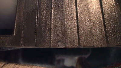
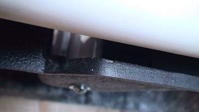
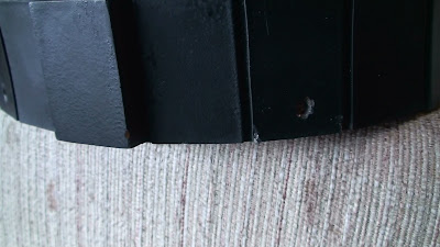
I used plumber’s epoxy putty to fix the chips. I was tired of that pink/orange/melon colored Bondo stuff, and the gray putty was easier to work with and was more rigid on the corners.
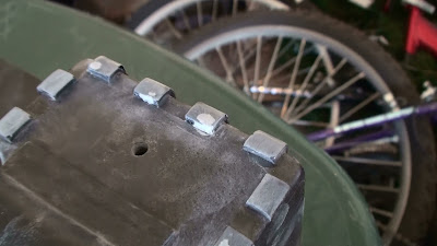
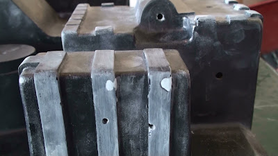
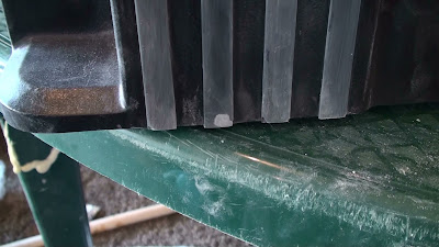
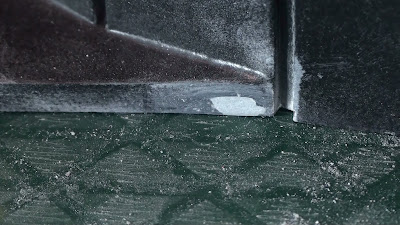
I also sanded the ribs and other parts of the shell that I wanted smooth.
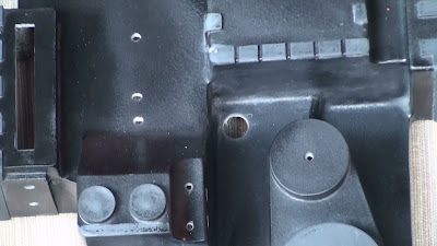
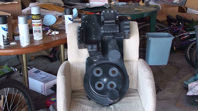
After that, I gave it a nice sponge bath and rinse to get all the dust and debris off and do a final inspection. It’s all ready for paintin’!
Things started getting particularly exciting when I started to prime and paint the parts I had labored so hard on.
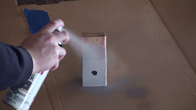
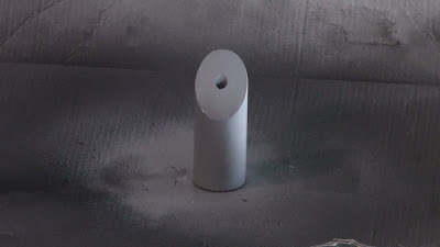
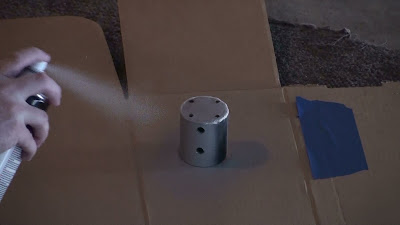
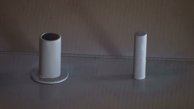
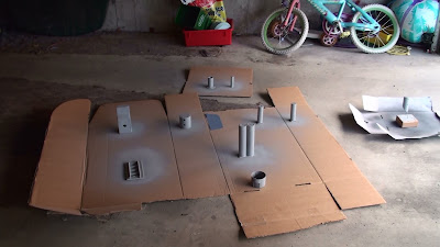
I was still uncertain about the N-Filter holes. I guess a part of me hoped it would just fix itself, but there simply was no ignoring it. Throughout the entire build process, I continued to putty and sand trying to get those holes to look right.
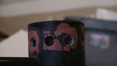
The problem was, as I mentioned before, that this spot putty just wasn’t the right stuff. It’s just too brittle around the edges. And that gave me the idea that the paint would probably hold that together better. I got it to this point and then primed the shell.
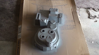
I love how this Rustoleum automotive primer coats so I did the first coat this way and inspected for any imperfections which may need sanding. Surprisingly, there wasn’t much to do. For the N-filter, I added some more putty to the holes on top of the primer, and used a dremel with a small sanding attachment to round out the holes. Then I added a second coat of primer to the shell, this time with black.
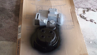
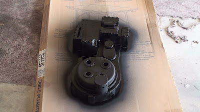
After that second coat of primer dried, I inspected the N-filter holes once again, and this time they looked much, much better.
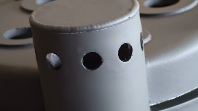
Most of the imperfections would be covered up by the final coat. The rest are small enough that unless you are getting down and putting your face right up next to it, you’re not even going to notice. It ain’t perfect, but a far cry better than it was originally. At least I can say I learned something, eh?
Parts getting painted black:
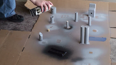
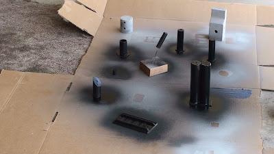
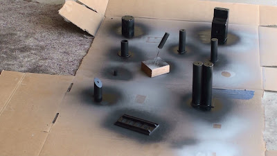
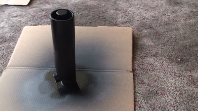
I gave these a couple of coats before calling 'em good.
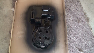
I also painted the motherboard with the last bit of flat black I had:
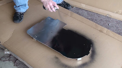
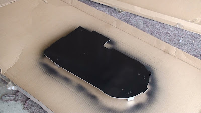
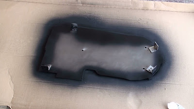
Oh, and I can’t forget about this part, the Ion Cap painted:
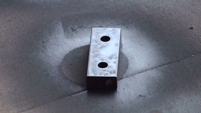
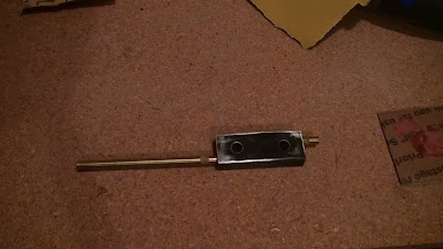
The paint did something weird on that, probably because I forgot to wash it first. But it’s not supposed to be a nice clean coat anyway. I later sanded it to look like this:
For the crank knob, I originally tried it gray, with just the primer color. I thought having it gray would help it stand out from the rest of the pack. But when I put it on, it just didn’t look right. So I decided to go black, which I believe is accurate for a GB2 pack anyway. My pack seems to have more GB2 style to it, so I think that decision was appropriate.
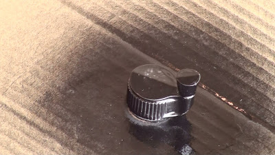
I thought I would test out the satin paint on this part to see what it would look like, and I had problems with it. The first problem is that despite having a coat of primer on it, it reacted kind of weird and didn’t coat quite right. And the second problem is that my area is so dusty, it started getting all yucked up. The satin paint takes a lot longer to dry, so I knew this would be an issue with dust particles. Then when fully dried, it was way too glossy for my liking. I ended up sanding it off and repainted it with flat black.
Primed and painted the bumper (one side at a time):
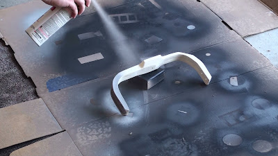
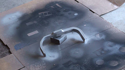
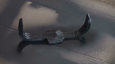
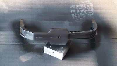
In that last shot, the paint didn’t cover the Bondo spot putty well with the first coat. It kind of looks like there is a couple of roughs spots, but it is actually very smooth. Thankfully, the second coat took care of it.
I had my shock mount replica on order from Nick-a-Tron, but it hadn’t arrived yet. So I made a temporary out of a dowel just so I could size things up. Kinda cute, eh?
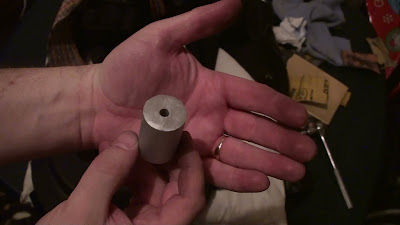
Certainly no substitute for the real thing. Literally, just as I was about to temp mount that, my order arrived from the UK.
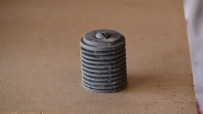
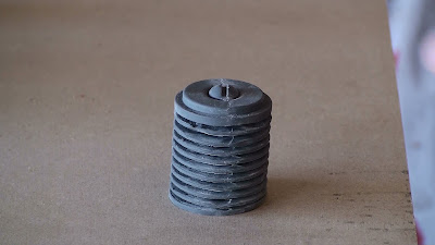
Now I’m no expert, but I was somewhat surprised that this wasn’t perfectly straight vertically. I know he cast this from a screen used one, but this just didn’t look right to me. Nevertheless, I assumed it was accurate and went ahead and cleaned it up and painted it.
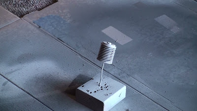
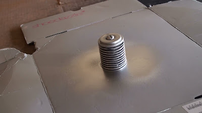
After that, the slight vertical angle to it didn’t bother me at all. I think it actually gives it some character.
Here’s an earlier picture of my parts after most of them were painted. They are just screaming at me to put them on the shell!
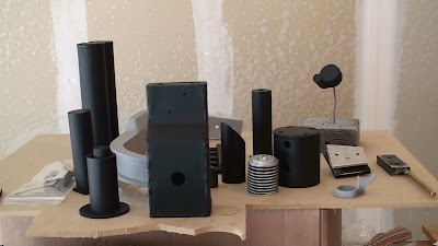
I don’t know if you guys feel this way, but after building most of these from scratch, I feel so attached to them! Like they are my family. I love all of you little guys!!! Give daddy a hug! 
Ahem…sorry. 
I’m getting a paranoid feeling like some short guy with a funny foreign accent is gonna jump in this thread any minute and say…“Everything you are doing is bad. I want you to know this.” 
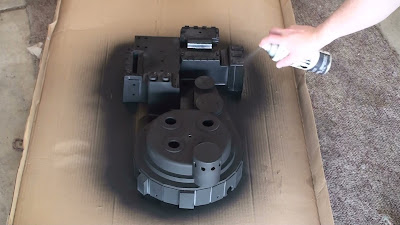
Anyway, here is the final coat of paint going on the shell. Flat black, dries fast, and looks good to me.
Everything you are doing is bad, I want you to know this… Lmfao
The packs looking awesome my friend… Very nice