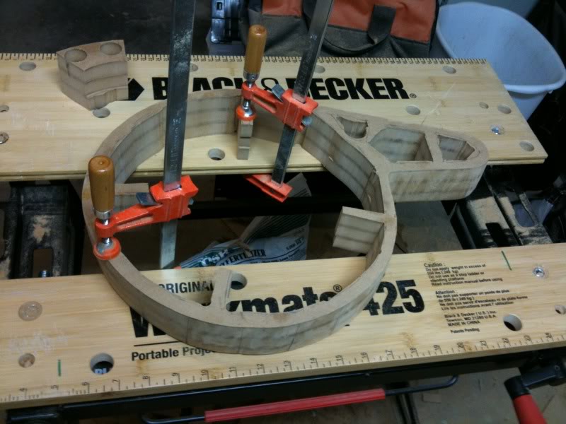
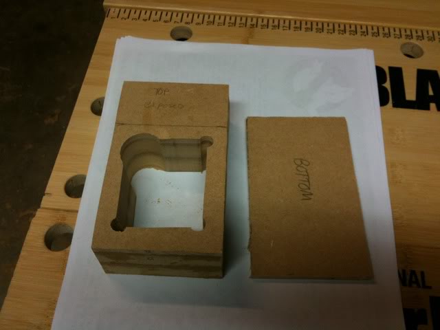
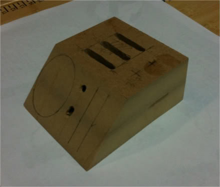
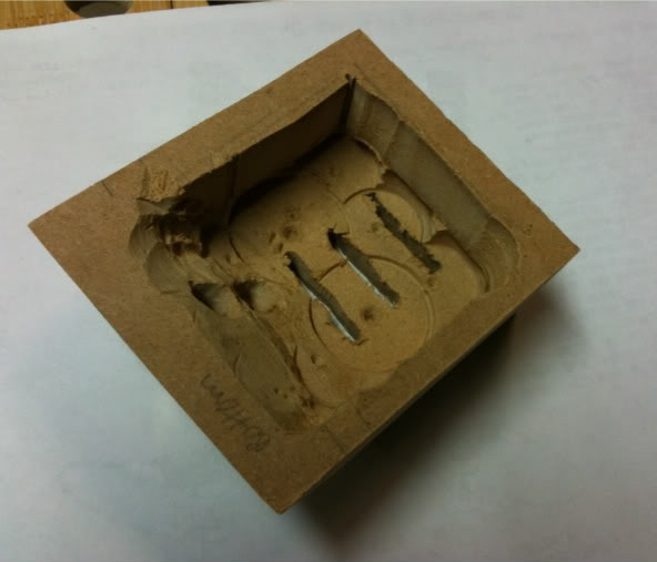
Here are some pics from my 1st pack build (a work in progress). It’s a scratch build, mostly from 1/4" MDF. The motherboard is 1/4" birch plywood for extra strength. I’ll be using 1/8" basswood strips for the fins. I made an aborted attempt last Halloween, and this year decided to go for it. I started out trying to build something simple and quick, and rapidly caught the bug and have gone overboard. It won’t be totally screen accurate, but I’m trying for as close as possible within the limits of my workshop, and without buying replicas / casts if possible.
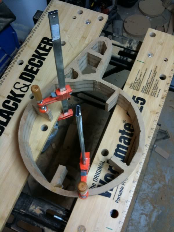
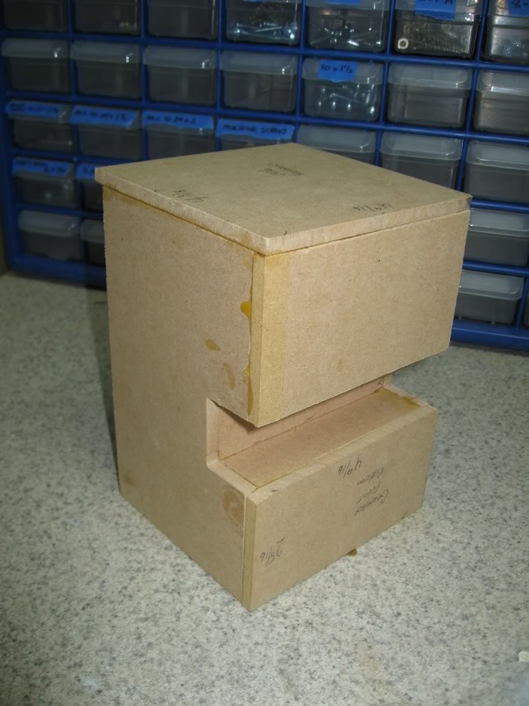
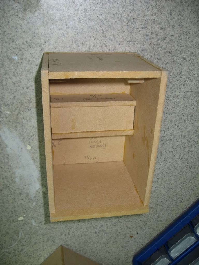
Here you can see how the pieces were glued together. I’m using TiteBond glue, and it seems to work very well so far. I made it with a back (not shown). And no, I’m not real sure why I did that. Seems kinda useless now. I think at the time I was thinking I would need it for structural integrity, but it seems pretty solid without it. If I were to do it again, I’d forget the back and maybe run a dowel across the middle of the back for support.
The outer box was constructed first, then the walls of the vacuum pump inset were glued in place later.
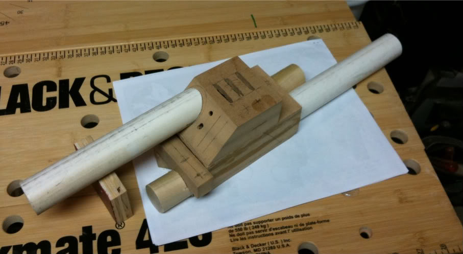
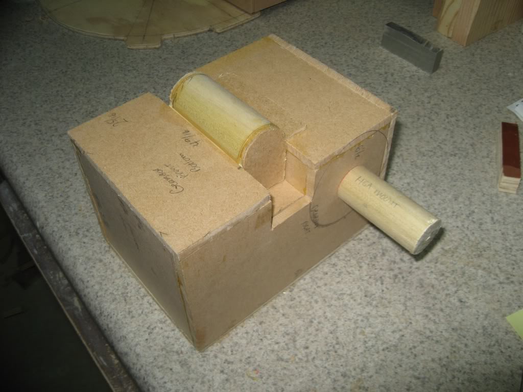
Here I’ve added the vacuum pump tube (a dowel, with 1/8" MDF arches on either side, and dowel to hold the HGA. The screw in the center of the HGA screws into this dowel to hold it in place. Screwing this dowel into the side of the gearbox was the biggest pain of the entire piece, since I didn’t do it until I had already built the box, and then there’s no room inside to get a screwdriver. I had to use a socket wrench with a Philips bit on it, and it was a bitch to hold in place and slowly ratchet in place. Note to self - put that screw in the side before gluing the box together next time.
This was constructed first. It’s probably a good first piece, as it’s simple (without the fins). I made mine solid, because I was worried about supporting the gun. In retrospect, the other glued together boxes have been very structurally sound, so I probably needn’t have worried, and could have built a box out of MDF.
This was made out of some cheap pine I had lying around, with a piece of 1/4" to bring it to the right width. I wouldn’t recommend the pine; it’s just not a fine grained enough wood to get a decent finish on.
You can see the spacer blocks to keep the gunmount separated from the gearbox. I probably should have saved myself some time and just made these out of foamcore.
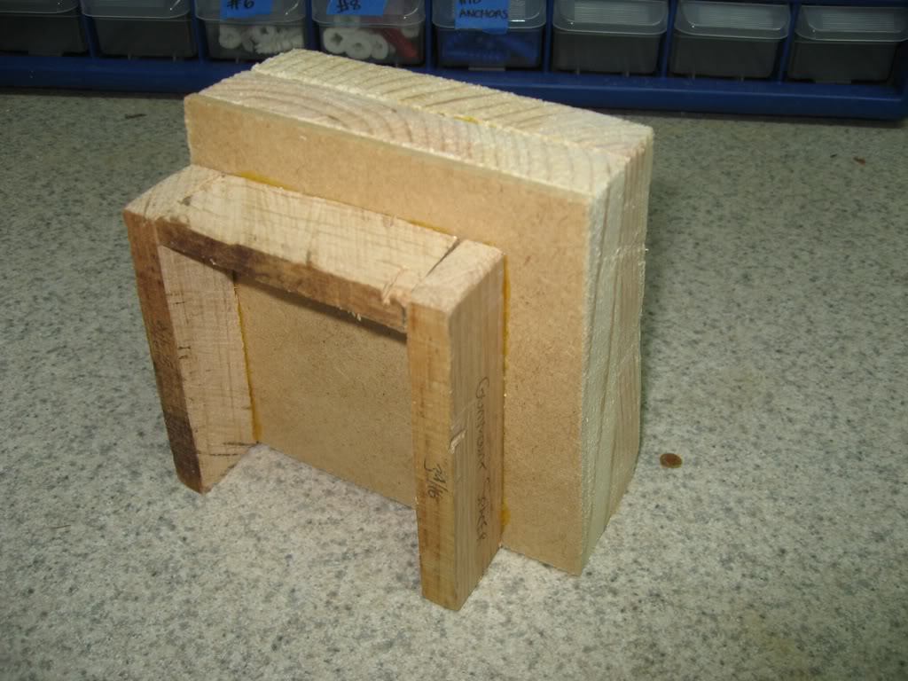
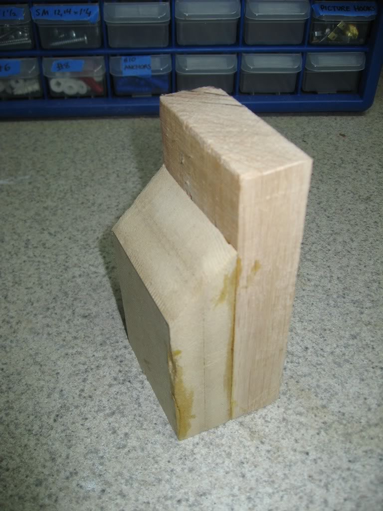
This is a block of solid 1" oak for the arm, and two 1/2" MDFs glued together for the angled part. It’s pretty darn solid. I suppose I probably could have just made it all out of MDF. I hope my back is strong enough to carry all this. Actually, I did drill out the inside faces of the MDF and oak a bit to lighten it up, and it’s not too bad. (Note to self – Gotta get a router)
Needless to say, this piece was pretty easy to fab. Note to noobs: glue the angled pieces together before cutting the angle.
Back of the EDA (upside down). This is a fairly easy piece to fab, but I still managed to make it hard on myself by building it in two pieces. Not sure what I was thinking there either. I should have cut the front face as all one piece, and the top as one piece (which is at the bottom of this picture).
PPD area. This wasn’t too tough, but took a while since I took it slow to make sure that I got all the measurements right and double-checked all the cuts. Sanded the cut lines a bit to ensure straightness and a fairly tight fit. To get the ~45 degree angles on the roof edges, and the face edges, I just clamped it a vise and used a rough rasp to put an angle on the edge.
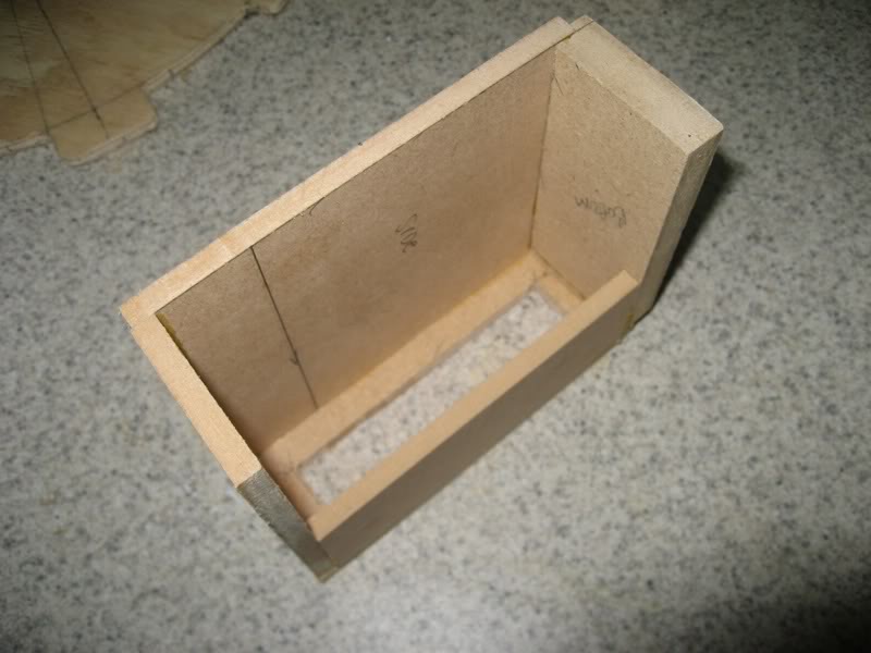
Inside of PPD. Note that the piece that goes in back of the PPD cylinder stretches across the entire width of the box. I cut a slot into the top of it for the piece that goes along the side of the cylinder to fit into (that piece has a corresponding slot in its bottom, and that piece goes all the way to the back.
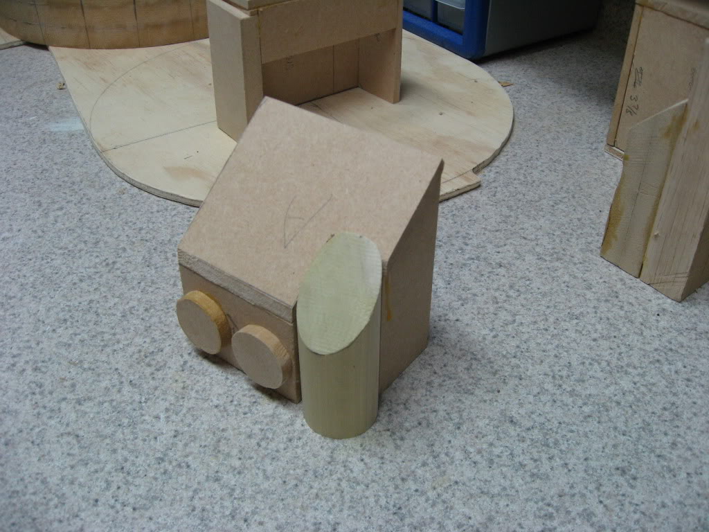
This was fairly straight-forward to fab. The bottom block was a bit tricky, as I did it in one piece, with a notch cut into it for the left side to fit into. Probably would have been easier to just use two pieces of 1/4" MDF glued together.
For the hole in the front face, just drill out a decent size hole (1/4"), and then insert jig saw and have fun. Use a rasp to finish out the corners where it might be hard to get the jigsaw into.
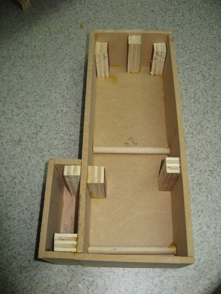
Inside view of the power cell. Left the right side open for easy access to the electronics that I hope will eventually live there (that day seems a long way away now). I’ll probably drill a few holes in the left side of the EDA box to run wires to the switch that will be up on the top left side of the EDA.
I’m hoping to attach this to the motherboard and/or EDA in a way that allows for easy removal so I can replace batteries and futz with the electronics. Haven’t quite thought that through yet.
Also need to buy some plexi or plastic for the blue window in the front. Somebody recommended those little plastic boxes at the Container Store. There’s a Bed, Bath, & Beyond right near work, so I might go over there and see if they have anything I can use.
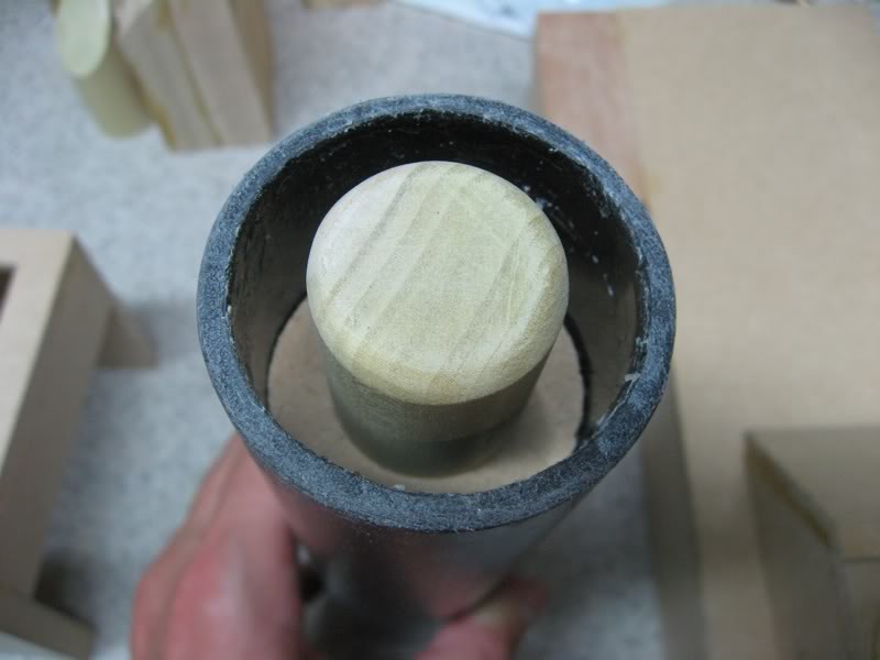
That’s a 1" or 1 1/4" dowel in the center (can’t remember which), screwed into a circular disc (custom cut), and pushed down and glued into the pipe. Actually had the forethought to sand the dowel before mounting in the pipe! The circular disc is 1/4" MDF, marked out with 1" radius using a drafting compass, and then cut to within about 1/16" of the line with a jigsaw. Then I used the rasp to take it closer down to the line, testing it out every now and then and stopping when I got a nice tight fit. You don’t want to overcut a plug disc like this.
Here’s a bunch of stuff lying together showing how they fit. The angle of the camera is a bit off, so it looks like the booster sticks up above the EDA much more than it does.
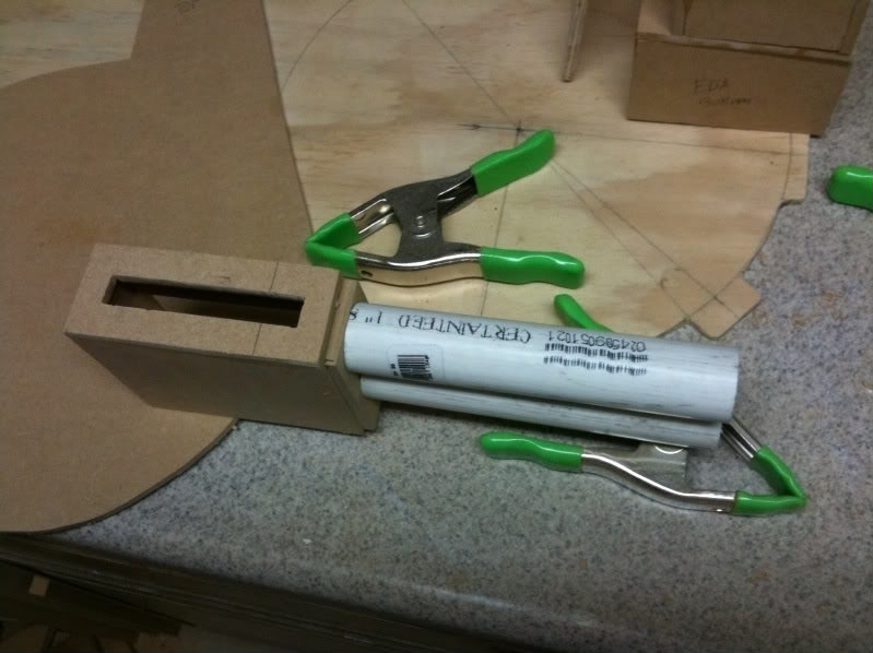
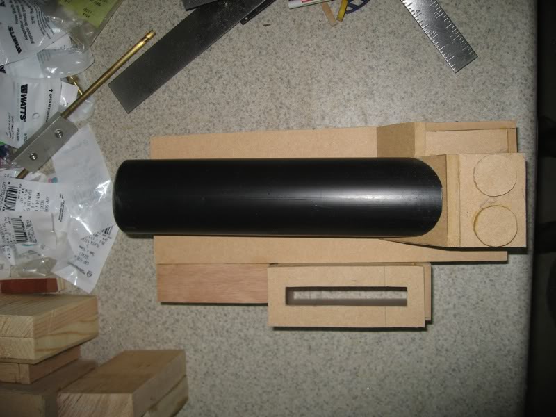
Cutting the bottom of the booster: It’s a 50 degree cut; I agonized over this one for a while. A chop-saw or a mitre box would have made it easy (heck then I’d be mitering my box joints!). The problem is how to draw the angled line onto a cylindrical surface. I’m sure someone out there knows the right way to do this, but I don’t. In the end I used my daughter’s school protractor to draw the angle on a scrap piece of 1/2" MDF and cut it. I then clamped the pipe alongside a board, then laid the angled MDF across the top of the pipe, clamped it to the board along the side and to the pipe, and used the angled MDF as a guide for my hacksaw. Worked fine. No adjustments necessary at all!
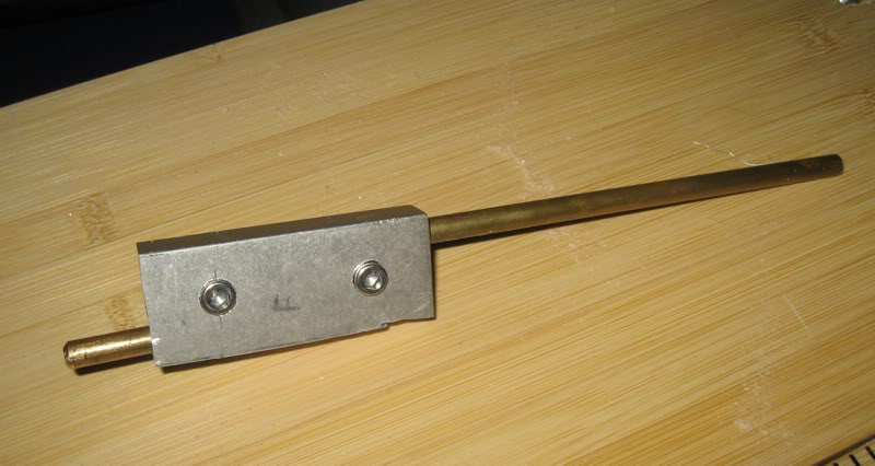
Found some scrap aluminum at HSC Electronics in Sunnyvale for about $2. Cut it with a hacksaw (sloppily, it’s a pain). Then spent forever with a metal file filing down the rough cut edge. Suprisingly my hand drill was able to make very nice holes for the brass rods (1/4"), and for the countersunk socket cap screws.
You can see a bit of a hacksaw goof at the lower right of this photo. I’ve got to file it down a bit more, but I’m going to leave that part a bit rough. Hopefully it will make the pack look a bit more weathered.
Good saws. I don’t have a mitre saw or table saw, which would be very nice for their very straight cuts. Circular saw is way too big. Hand saws are fine, especially with MDF, but it’s hard for me to cut a really straight edge with them. My Hitachi jigsaw is pretty good at making good, straight cuts. And it’s fast.
Good quality combination square for measurements and true right angles.
Lots of good clamps. I’ve got several Irwin 4" Quick Grips, about 4 12" clamps, and a whole bunch of little tong shaped thingys. I could probably use a bunch of 6" clamps too. These are essential for clamping the boxes together while gluing.
Wood rasp, for filing down edges and cuts quickly. Get one with at least two different size rasping surfaces.
Decent drill, with a wide variety of bits. A drill press would be nice, but is not necessary (so far).
Metal files, for filing down your copper rods, aluminum blocks, etc, if you use them.
Hacksaw for metal work, as well as cutting PVC pipe.
Drafting compass and protractor for drawing circles and angles.
Good wood glue. I’m using TiteBond.
Sander. I’ve got a new Porter-Cable 5" random orbital sander coming from Amazon in a day or two. Can’t wait to fire that baby up! I probably need to get something for detail work too, like a Dremel or something. Anyone recommend anything?
We all know that projects like this are just an excuse to load up on tools, right? That’s what my wife thinks anyway.
One thing I noticed: you will need to remove that vaccum pump dowel rod. The reason most peope use pvc pipes instead of dowel rods, is things like the hose needs to be inserted into them.
I used short dowel lengths to mount onto the mb (using pre drilled holes and wood screwes to mount them to the MB), and then slipped pvc pipes over them and glued them to that.
The advantages of pvc are:
Price (its dirt cheap!)
Texture (no wood grain to remove.. it looks more like metal painted up properly)
Re the motherboard, looks like you’re right about that. I had cut the MB last fall during my 1st aborted attempt, using Norm’s plans. Haven’t had a chance to go back and review how that fits with Stefan’s more accurate plans, but as you pointed out, it looks like it’s not quite the same. No problem, I’ve got enough plywood to cut another MB. I may even look into getting a thin piece of aluminum and trying that, although then I’d have to cut it by hand with a hacksaw or keyhole saw, and that sounds like real work.
Likewise my synchronous generator is a left-over from last year, and it’s a big heavy disaster. I’ve got to figure out what to do about that. I think I’ve got a plan for it, and I’ll post about that later.
Re the vacuum pump dowel, I was just blindly following Sean’s plans when I did that part, not thinking about what needs to be attached to it. I don’t think I’ll need to remove it however. I can just mount a small (1/2" long) piece of dowel on the right side, and attach the tubing over that. I’ll try it and see how it looks.
In general I agree with you about PVC. I will be using PVC for the injector tubes, for instance, and probably for the filler plug. Wish they made square PVC in the exact sizes of the gearbox and EDA!
Gareee: I think if I was starting over I might use insulation foam for the sync gen. It certainly would save on weight, and probably save a lot of time too. But since I’ve got the leftover sync gen from last fall, I’m going to use that. I’m considering using foamboard for the cyclo though. I’ve got a cake pan leftover from last year with holes in it already, and painted. But since almost everything else is scratch built, it seems lame to use a cake pan.
Stratopwn3r: I used three layers of 3/4" MDF for the spacer / synchronous generator. I rough cut them, then glued them together, and then cut them closer to the line with the jigsaw, and then rasped and sanded them down. I did all that last year when I was following Norm’s plans, and wasn’t very concerned at all with accuracy.
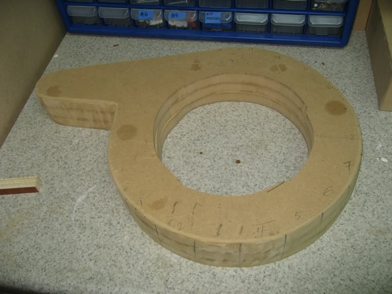
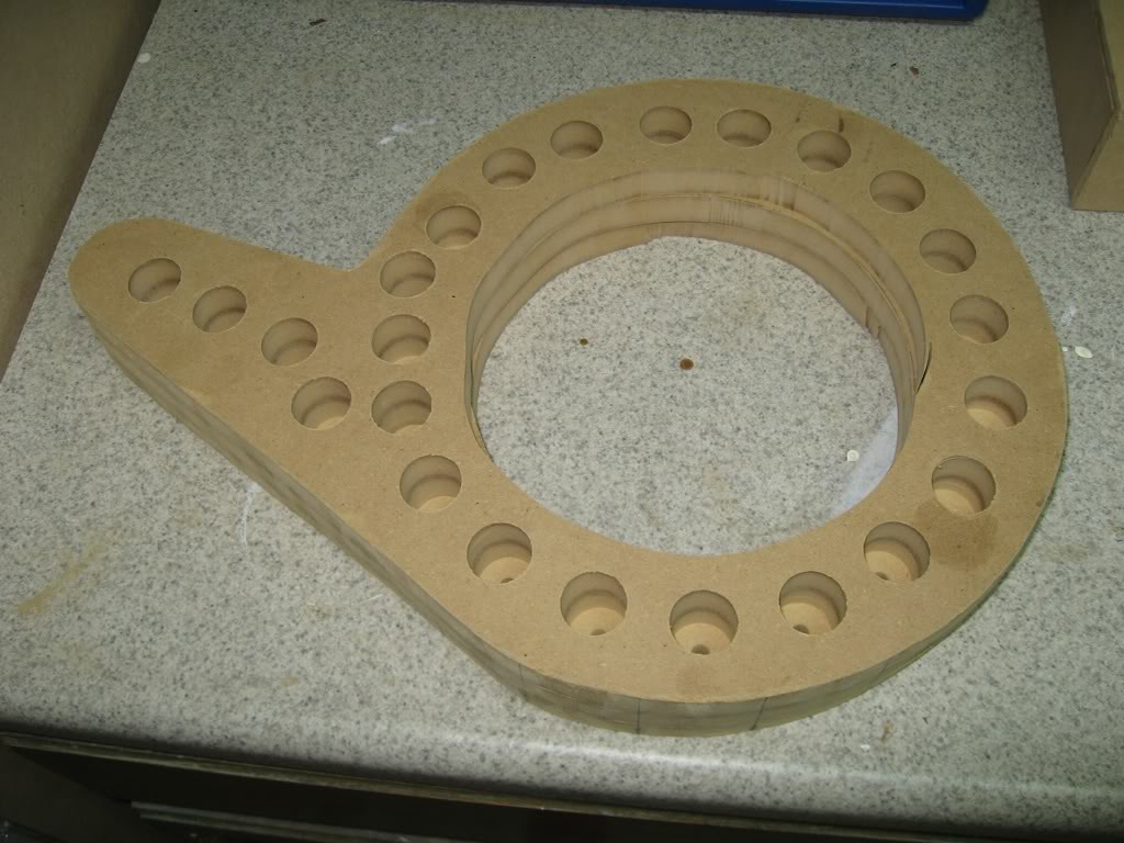
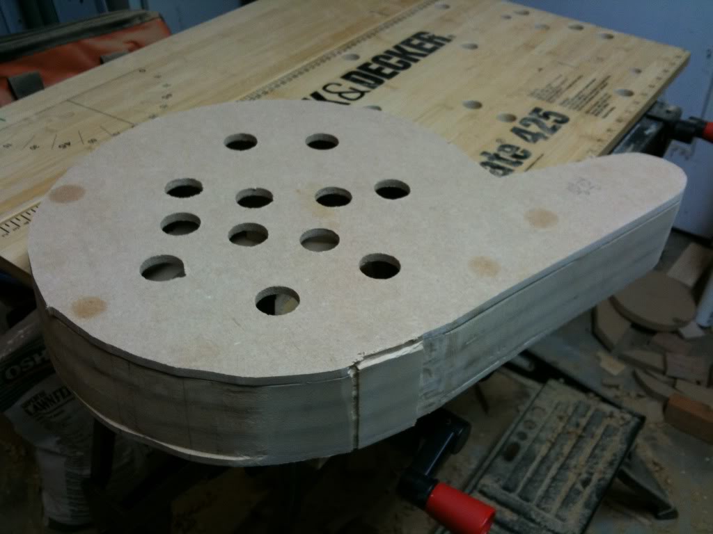
Bottom view, with holes cut into it to relieve the weight. I’ve really got to get a 1" Forstner bit for my drill so I can make large flat bottomed holes. Then I can go a bit deeper.
Now I’ve got to get it up to the correct height (it’s only 2.25" instead of regulation 2.75"), put the plates around the outside bottom, and take out some more of the weight. So here’s the current plan to transform what I’ve got into something workable:
Cut away major sections of the inside of my current sync-gen pieces, leaving about 3/8" around the outside, plus some supporting blocks on the inside.
Cut two layers of 1/4" MDF for new top and bottom of the sync-gen. That brings the height up to 2.75".
Glue the bottom 1/4" layer to the remaining sync-gen pieces
Sand away flat sections on the bottom half for the plates to fit against
Glue the top 1/4" layer on
Sand the top and the boundaries between layers; round the top edge over
Mount the bottom plates
Hopefully that will do it. If anyone can point out the flaws in my logic, that would be great.
Like I said above, if I was starting over on the sync-gen, I’d probably use foam insulation board, or I’d use 1/4" MDF for the top and bottom, and put foamcore blocks to hold the two apart, and then mount the 14 or 15 plates around the outside.
Question for you all: how do I get a smooth finish on insulation foamboard? I haven’t worked with it before, but it seems like it would produce a rippled/bumpy surface. I don’t imagine you can sand it. Can you putty it and then sand the putty? How do people get the right effect?
Last night I whipped off the injectors. Stefan’s plans call for 1.5" outside diameter, but I could only find 1.25" inner diameter PVC pipes, which are about 1.375" outside diameter. Close enough. They are mounted and glued onto 1/2" lengths of 1" diameter dowels, which are screwed into the base of the power cell. This didn’t really seem sturdy enough, so I put a countersunk 1/2" screw in the back of each one, screwing the pipe onto the dowel.
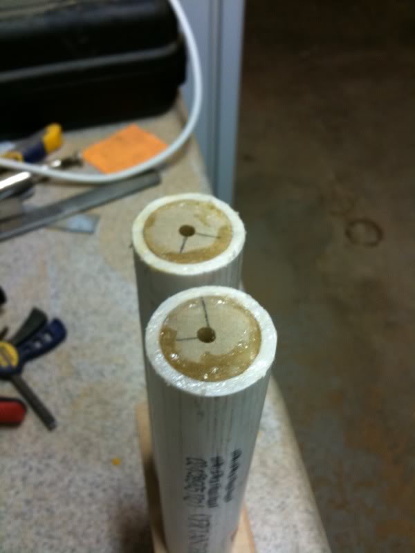
Here’s a shot of the ends. Those are 1" dowel plugs in the ends, glued in. There’s a 5/32" hole drilled in each end for the hoses to go into. In examining the reference photos of the injector ends, I think they’re pretty lame, especially compared to the rest of the pack. There’s no fitting really, the hose just goes into to injector. It looks a bit unrealistic. I might consider using some Clippard barbs or SMC straight fittings to upgrade the look a bit. I’d sacrifice some screen accuracy, but the gain in looks might be worth it.
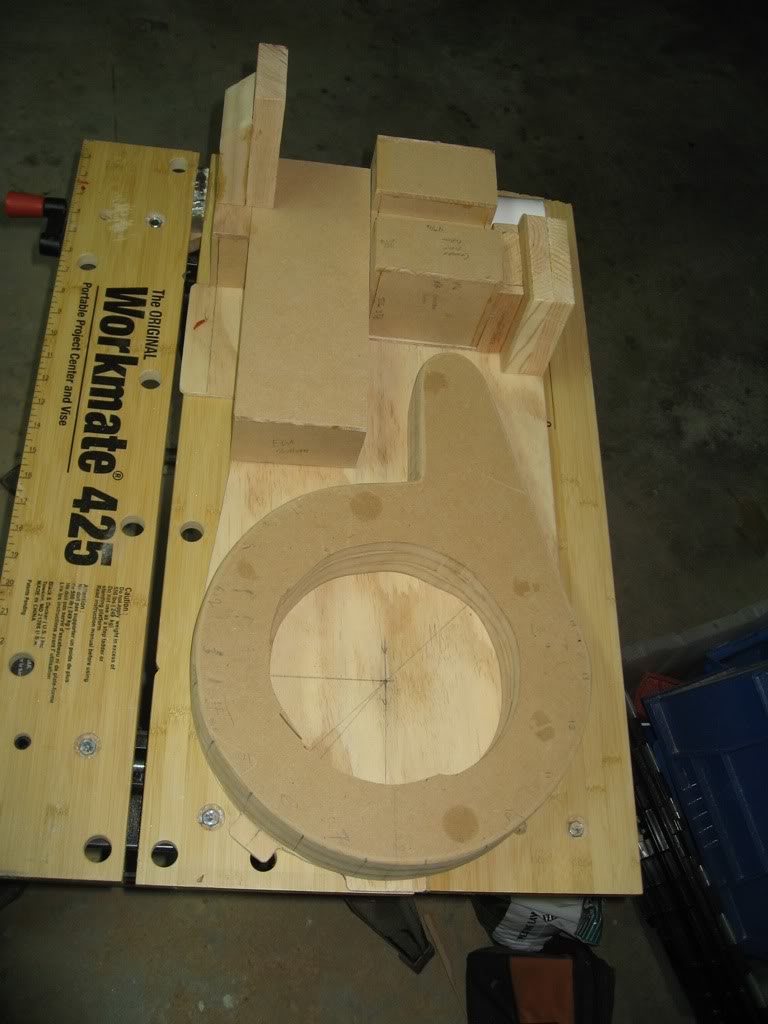
Last night I also cut down the behemoth old synchronous generator frame that I had built last year out of three pieces of 3/4" MDF. Must have cut down the weight by 85%. Also generated phenomenal amounts of sawdust, and put some wear and tear on the jigsaw. Bent one blade so I had to toss it. Afterwards, glued it to the bottom piece of 1/4" that I had cut out for it. Put a few of the small cut-out pieces towards the middle too, to add some support.
Of course, near the end, when I was moving it, I was a klutz and dropped the sync gen on the floor. It landed on the bottom of the circular part, and broke right through there. Luckily it was a thin, clean break, and the rest of it held. So I was able to glue it together and clamp it tight. This piece will be sandwiched in between two pieces of 1/4" MDF, so I don’t think that break will get much stress.
BTW, sometimes I use that big 25lb bag of fertilizer you see under the workbench to add extra weight holding down a board when I’m cutting it. Works great. No substitute for a clamp, though.
Next steps are to glue the new top on, then sand down the flat parts where the plates will attach. Then I can mount the plates, and that’s pretty much it for the sync-gen.
BTW, if you’re a noob go get yourself about four of those clamps I’m using. They are just totally awesome.
In other news, received my ALICE pack frame today (eBay), and the Nomex flight suit ($19.99 off eBay) arrived yesterday! Still gotta get a no-ghost patch and name patch. Will have to revisit that huge thread on patches (GBFans.com) and sort through who has the best patches… ugh.
Clippard stuff, SMC elbows, Nycoil banjo fittings, hoses, etc., still on the way. Still gotta figure out who has the best resin knobs too.
I cut holes in the top and bottom to lighten the weight, and also for wiring access through the top.
Turns out my old sync gen was a bit too big (wide). I was planning on sanding the bottom sections flat where the plates go, and then gluing on the plates. But it was already a bit wider than it should have been with the plates attached. So instead I’ve decided to rout out the grooves between the plates and along the top of the plates, and then sand them flat. So the plates won’t be separate pieces, but will just be routed out of the original sync gen piece. Took a crack at it last night and here’s the result. It’s OK, still needs to be sanded. Didn’t take too long with my Dremel 300 and a router bit.
I made a jig to be able to quickly do these routings, and to make them straighter. Will see how that goes tonight.
Finally started work on the gun. Here are the pieces so far, just roughly laid out (nothing attached). I didn’t realize it before, but the body is quite big. I have an acrylic rod for the front barrel, just need to cut it to size.
The gun body is made up of a top and a bottom. Here’s the bottom – it’s two pieces of 3/4" MDF and one 1/4" MDF glued together, plus another 1/4" MDF base piece. I drilled a few large holes in the center and then used the jigsaw to cut out the entire center piece, reducing the weight, and giving access for wiring.
Here’s the top of the gunbody. This is two pieces of 3/4" MDF glued together, and then the angle was cut into it. I’ve started to make the holes for the switches and vents and so forth. The vent holes were made with the Dremel; the switch holes are drilled and countersunk from the interior. I haven’t done the bargraph hole yet because I’m still trying to track down accurate measurements on it – Sean’s plans indicate 5/8" high, which seems way too short.
I’ve got the dowels and instrument bar roughed out. Still need to cut the piece that goes on the left with the Activate and Intensify switches. Plus work on the front barrel (ugh!). I might need to buy some resin parts for that, those little pieces really look like a pain to fabricate.


 That’s what my wife thinks anyway.