Proton Pack Build

To make a long story short, I decided to redo the shell completely. I tried several upgrades but still wasn’t satisfied with the resin shell. It continued to bother me that it was from a blacklisted seller and I kept finding inaccuracies.

I wanted to mention a few learning experiences (before I started over). I cut out the original cast-in resin N-filter and replaced it with an aluminum one from GBFans. This was so I could add the awesome Fincher e-cig venting kit.
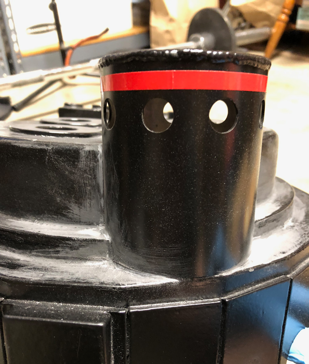
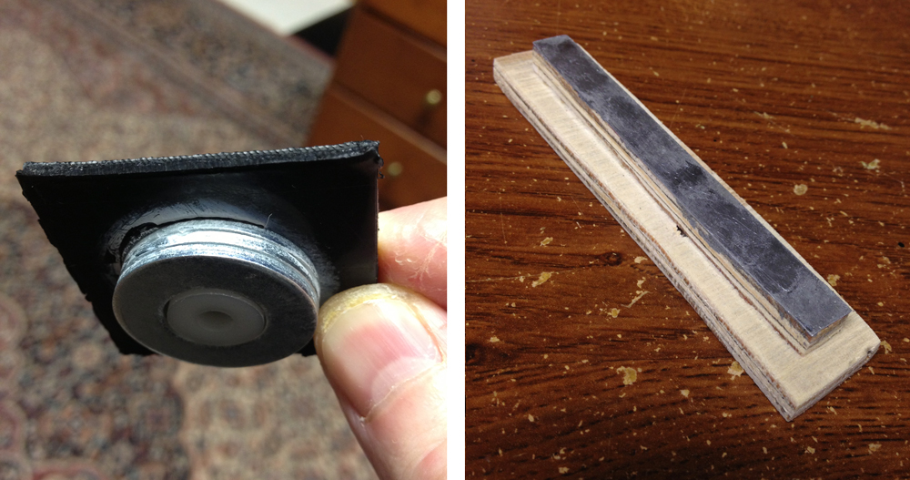
Instead of repainting the entire shell again, I only did specific areas. Before doing this, I worked on improving the power cell window and cyclotron ring holes. I made depth gauges to help.
Although my shell texture wasn’t that good to begin with (spray texture), I lost all texture on the cyclotron. I followed Chris Bosh’s tutorial to retexture and was amazed by how well it worked. Bosh’s tip about soaking the Homax in hot water made a huge difference for me. For my new shell, I will definitely use his tutorial again.
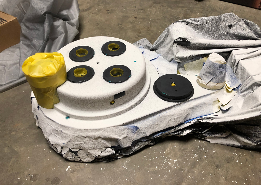
After repainting, I had a new problem. I had cut off my original N-filter and was, unfortunately, all out of dry transfers. GBFans didn’t have any for sale at this point and I couldn’t find anything that looked nearly as good.
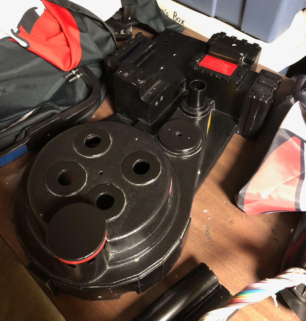
After doing some googling, I realized it wasn’t that difficult to get these made. I wanted it to look similar to the GBFans transfer on my thrower. In Adobe Illustrator, I made a few variations (stroke weight, detail, size) and had some sheets printed up in two shades of red. I also included my logo and a little warning label for the MB (so I’d remember not to leave my pack on while charging).
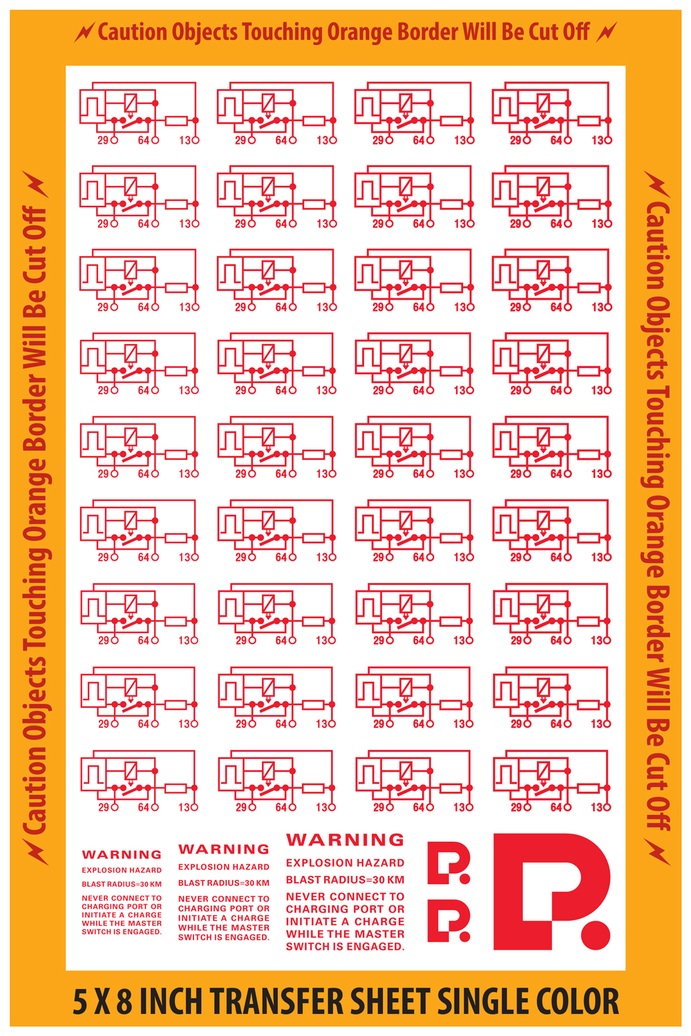
The top middle dry transfer is mine. The other two are GBFans.
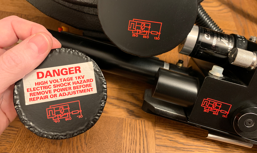
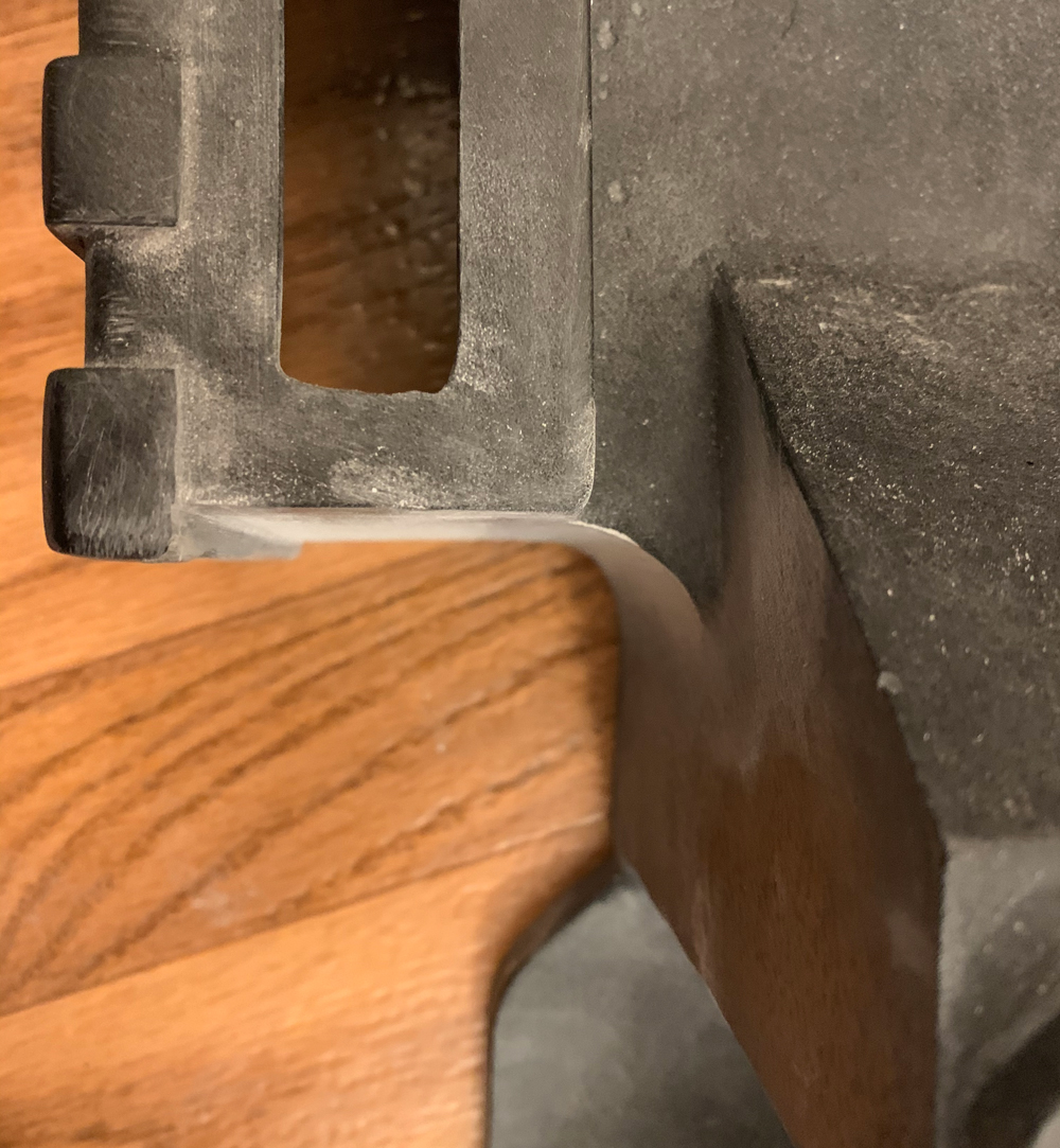
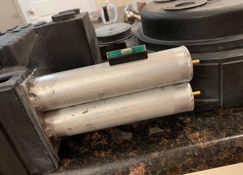
The last thing I did before giving up was make an L bracket for the injector tubes. Yet another cool detail I had no idea about. In trying to figure out placement, I found more shell inaccuracies that I hadn’t caught before.
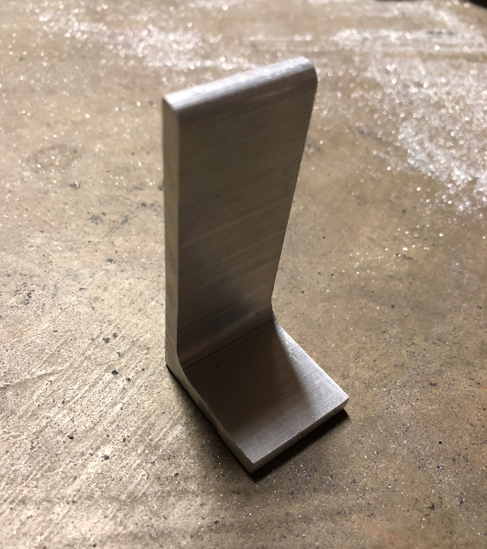
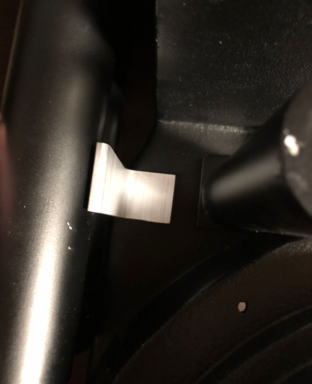
And here is the overhauled resin shell before I moved on. Considering how it looked before, it had come a long way. But at this point, I was hooked and had gotten too close to this project.
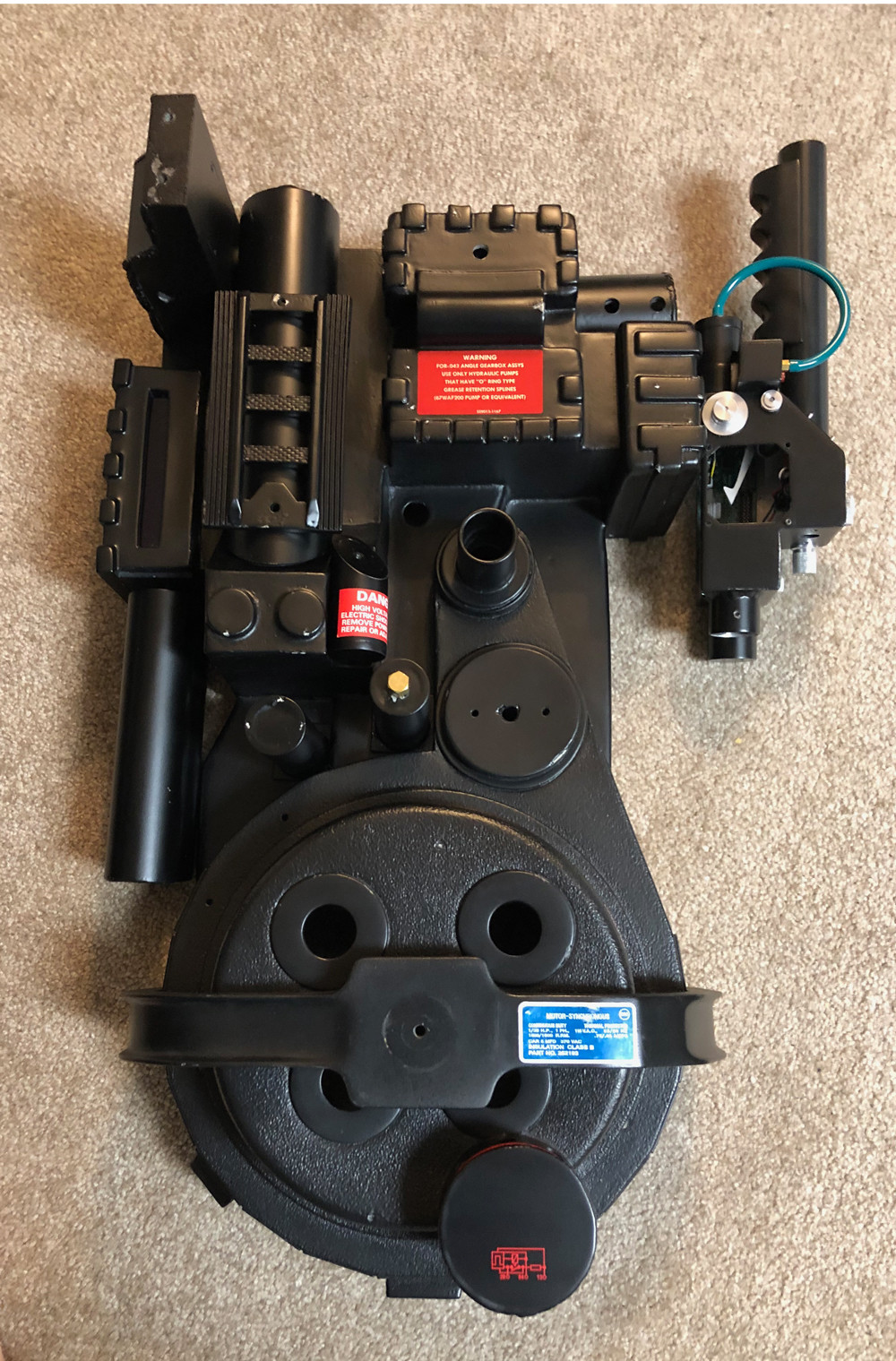
Don’t worry—the resin shell wasn’t abandoned.

I then considered several shells as a replacement. Some aspects of the idealized shells appealed to my own design sensibilities. However, I also loved the authenticity that comes from the odd quirks and imperfections of the real packs.

My first choice was too ambitious. I was going to get a GBFans shell but had the opportunity to get a variant of the notorious Venky shell. The connection to a real pack seemed very cool (Definitive History and Lineage of the Stunt Pack Shell, Bowelrock Shell Production Tied ?, etc.). There were also some big problems that I naively thought I could fix. More than anything else, I wanted to fix the valley and reduce the egg shape of the cyclotron. My plan included cutting the shell apart!
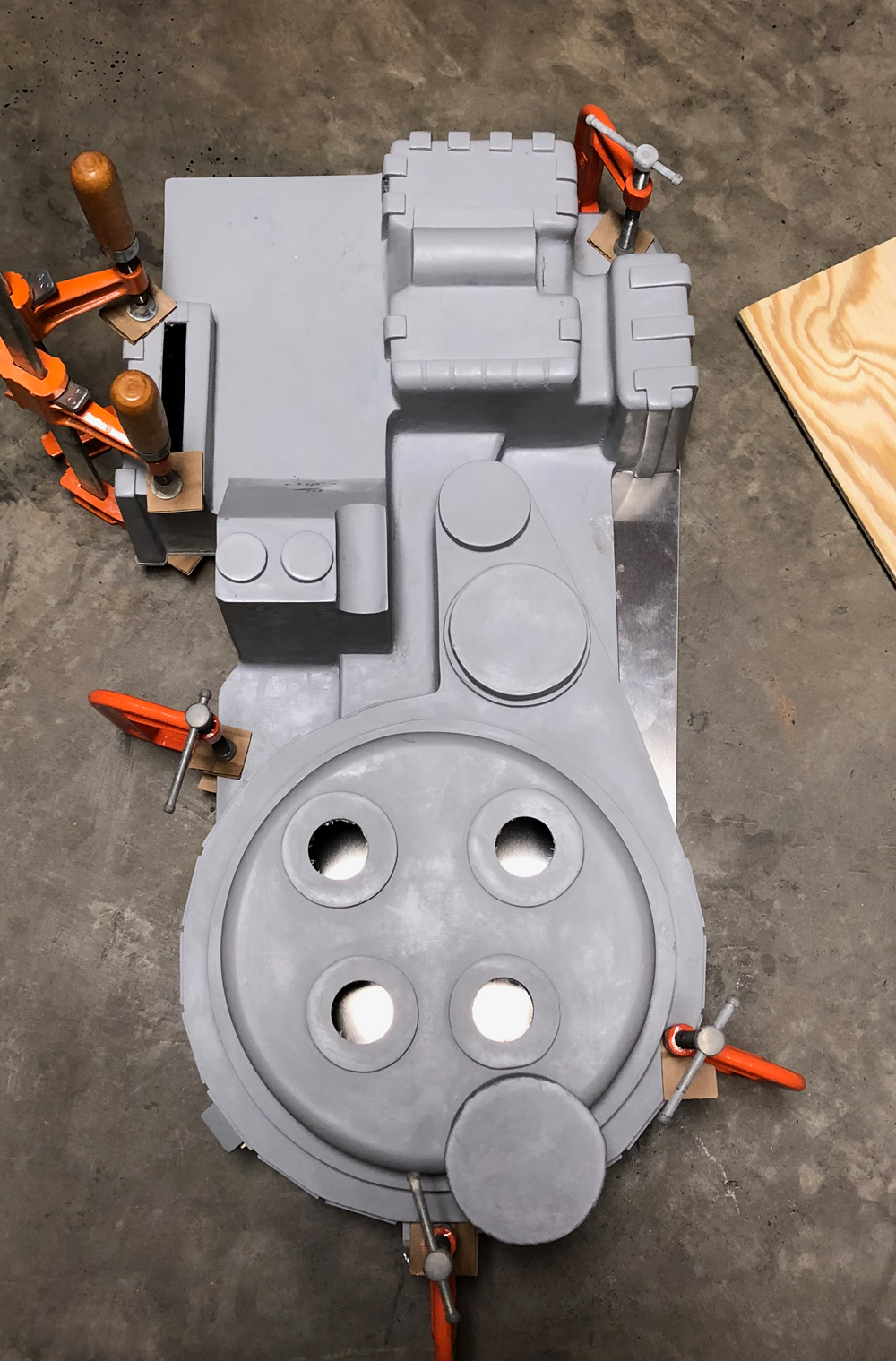
I needed accurate measurements. I spent a long time going over builds and staring at the reference pictures. I referred to these three builds the most: Updating Stefan’s Plans with New GBFans Plans, GBFans Pack Plans, and the Chris Bosh build. The information discovered by these prop builders and others has been invaluable. If anything on my pack turns out right, I owe it to this community.

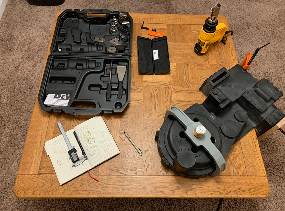
I compared the accurate measurements to the Venky variant shell using a digital caliper. As the list of fixes grew, I got overwhelmed. I also found measurements that didn’t match other Venky shells, which was baffling—some areas were smaller than the Venky—which was already smaller.
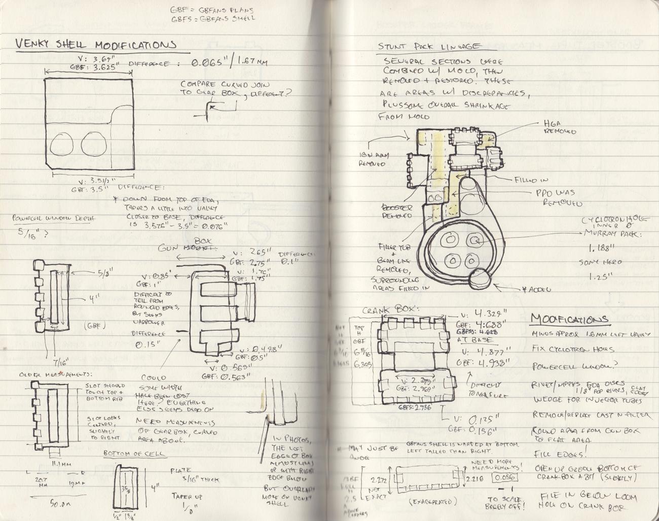
I might do something with this in the future, but decided this shell wouldn’t work for me. **Later on in my build, this shell has been helpful as another reference.*

So I switched to the GBFans shell. In addition to better accuracy, the quality and durability of the shell is excellent. Not that I would have tried doing something this reckless, but I bet I could sit on it and it would hold up just fine.
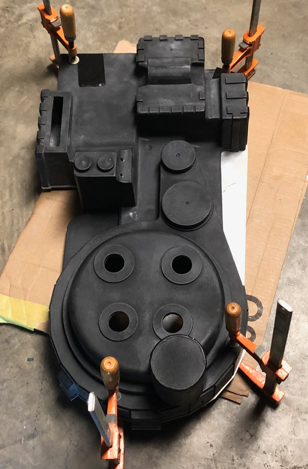
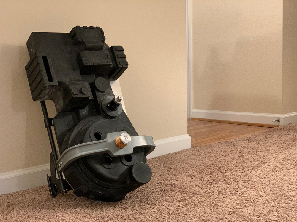
Although this was many steps backwards, it felt right. From junk to resin to fiberglass, I was now building a hero pack.

Interesting to follow your journey in this!

Point to note, I think the aluminium stock you’ve used for the injector tubes bracket is a bit thick, so you might want to revisit that still.

Thanks! It’s been chaotic to say the least.

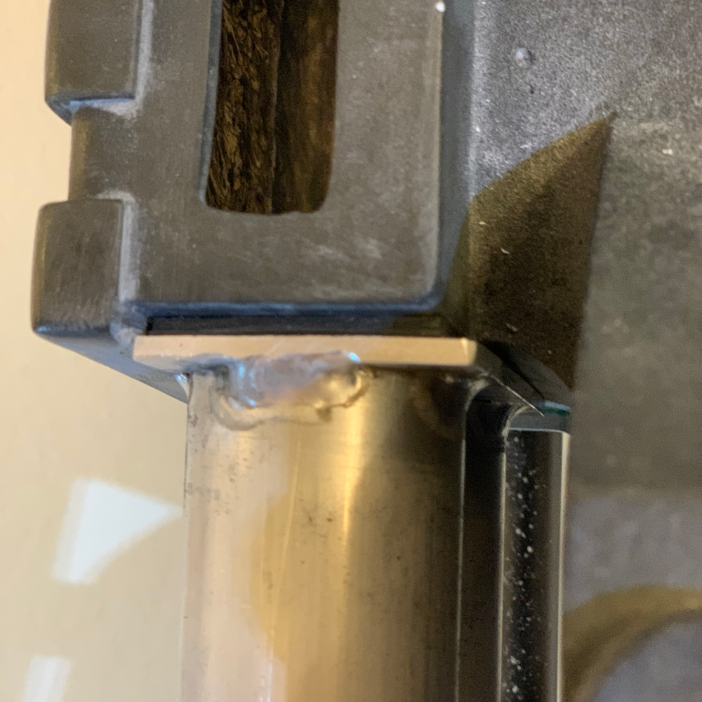
Good catch on the bracket. Later on, I ended up redoing the L bracket with 1/8". The original bracket also has an inner curve that’s thicker than the rest.

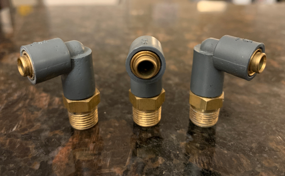
Before starting over on the shell, I had worked on replacements for a few components. I had already gone through several Legris elbow replicas, but wanted to get these looking more realistic. I was lucky enough to get some nice replicas from Mr_Stay_Puft. He cast these from real ones… and he better put those in a vault and look over his shoulder from now on! Joking. Mostly. :boogieman:

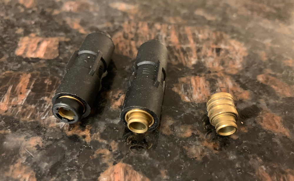
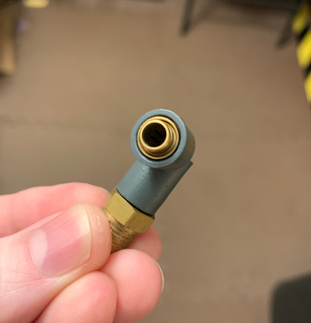
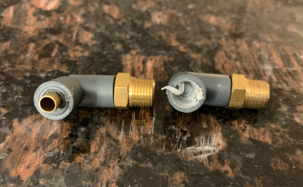
He had put real barbs in the bottom and a 5/32 brass tube in the top. I decided to replace the brass tube with a grab ring similar to the ones used in the real elbows. In the picture below, the elbow on the left still has the brass tube. I messed this one up a bit but it was originally in great condition. There are better pictures on Mr_Stay_Puft’s for sale post. The second elbow is one I started to drill out.

For the grab ring, I used “old new stock” Legris 4mm unions (3106-04-00). The push button and the grab ring are not difficult to remove.

Making room for the grab rings was not easy. I used a drill bit by hand to start opening up the hole. Then I used an X-acto blade to slowly whittle a new edge. I repainted with “Gunship Gray” and clear coated.

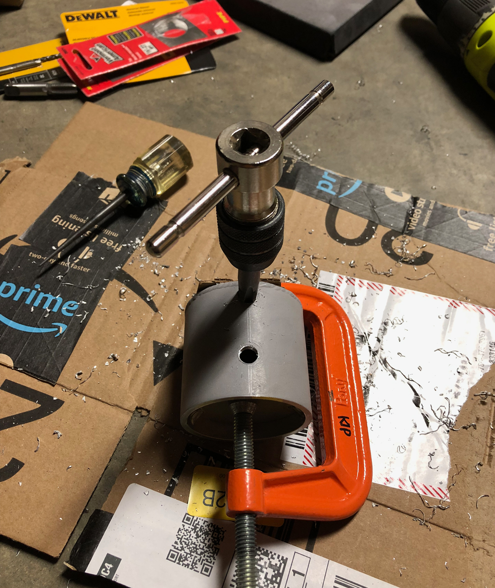
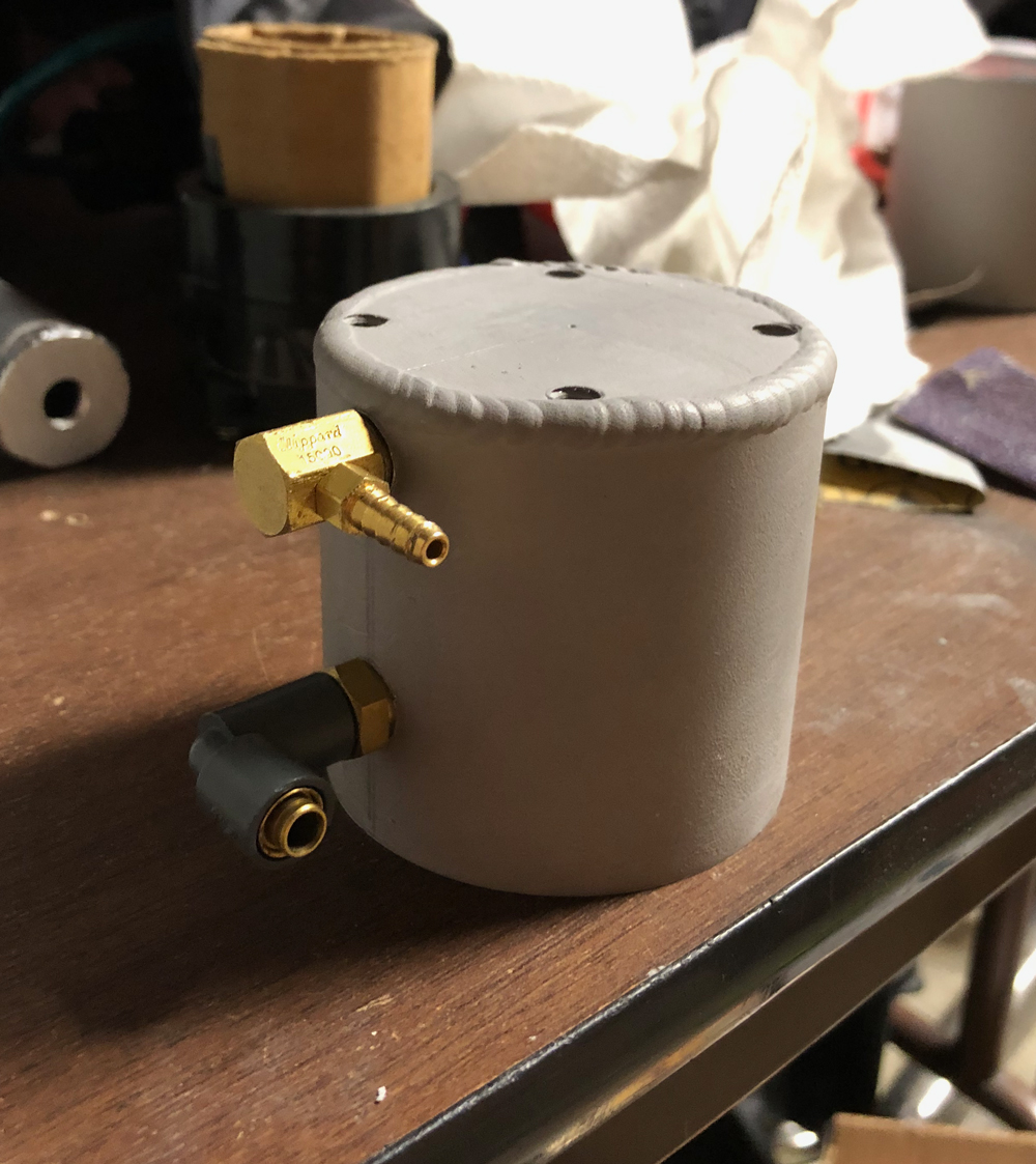
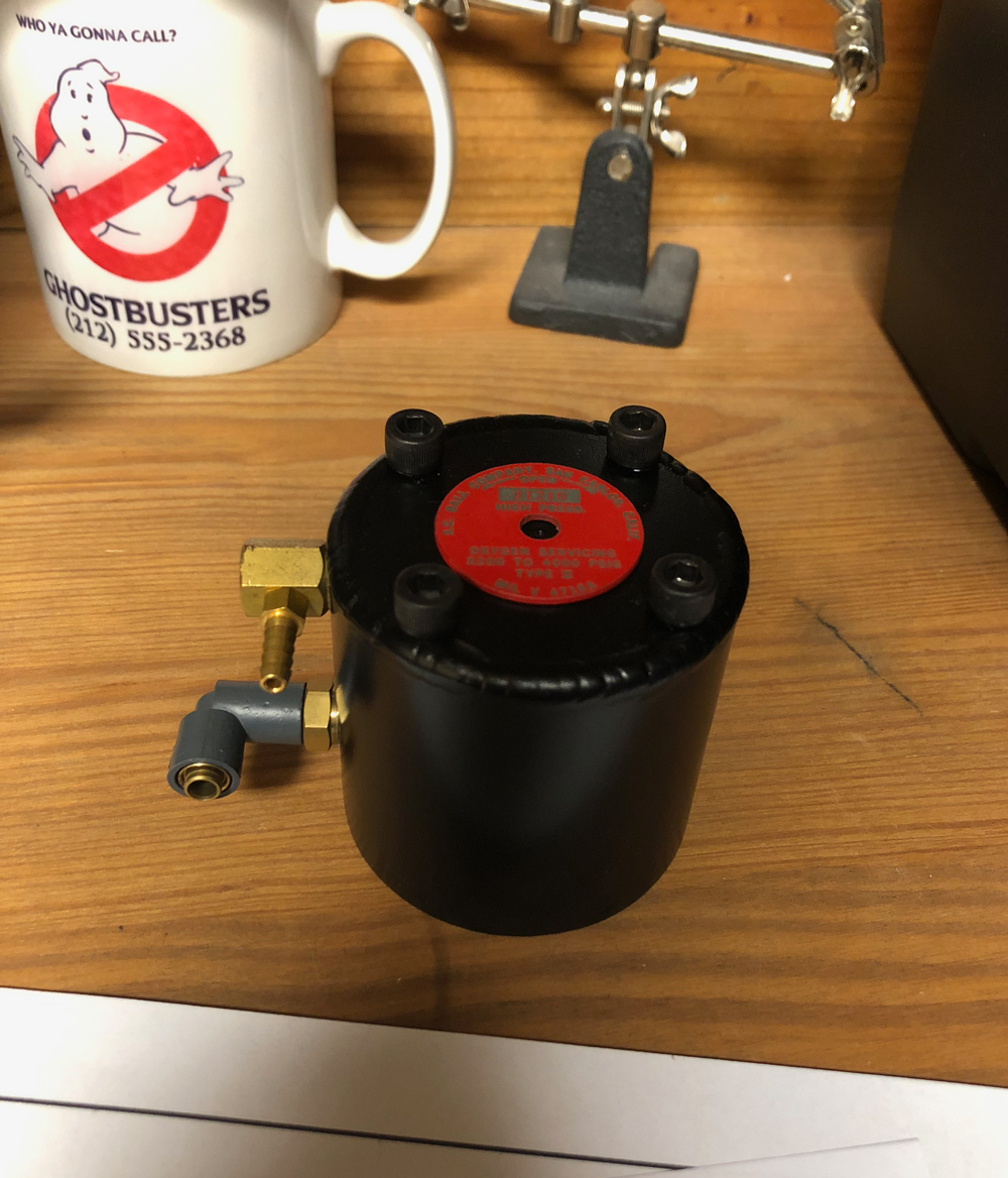
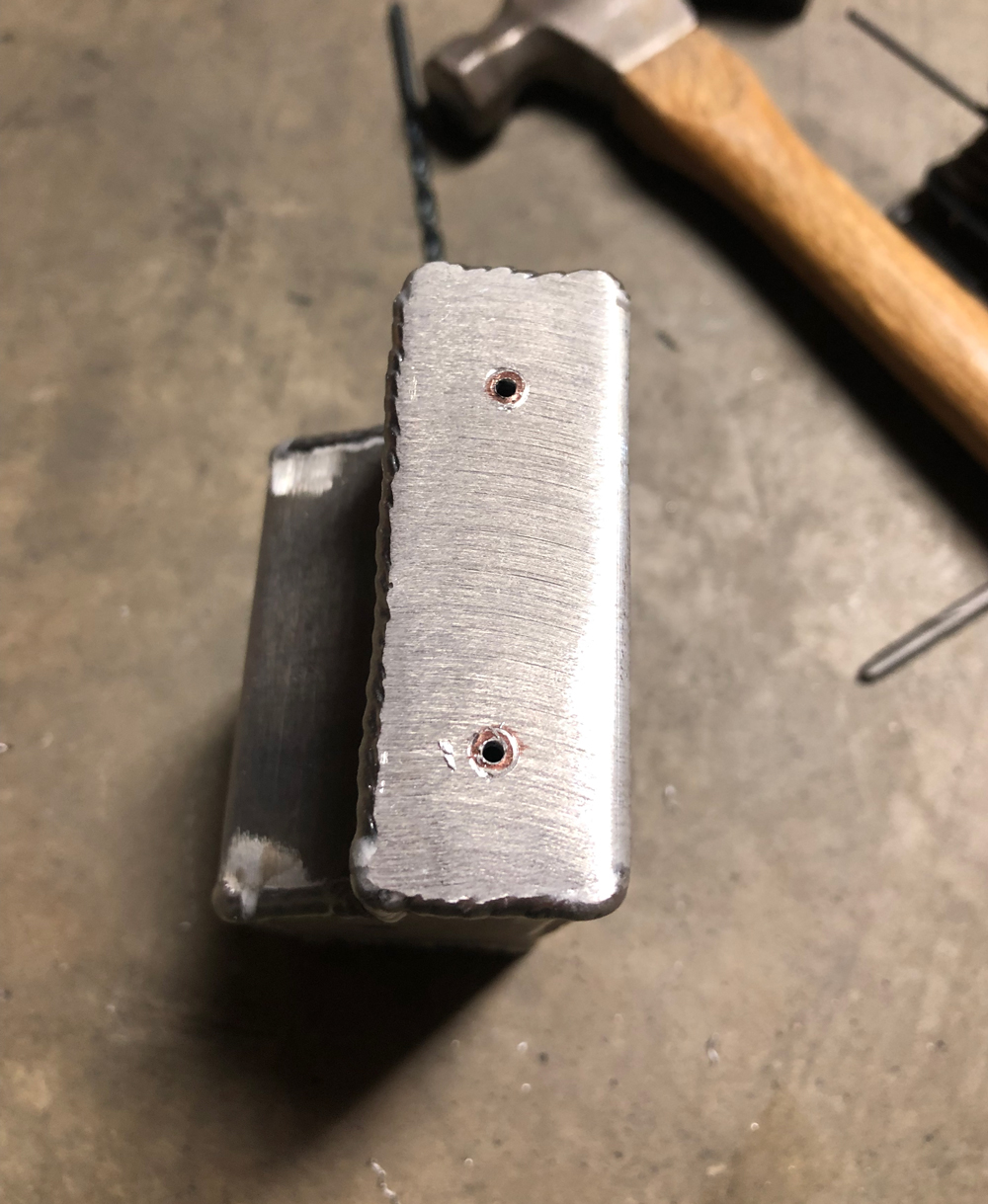
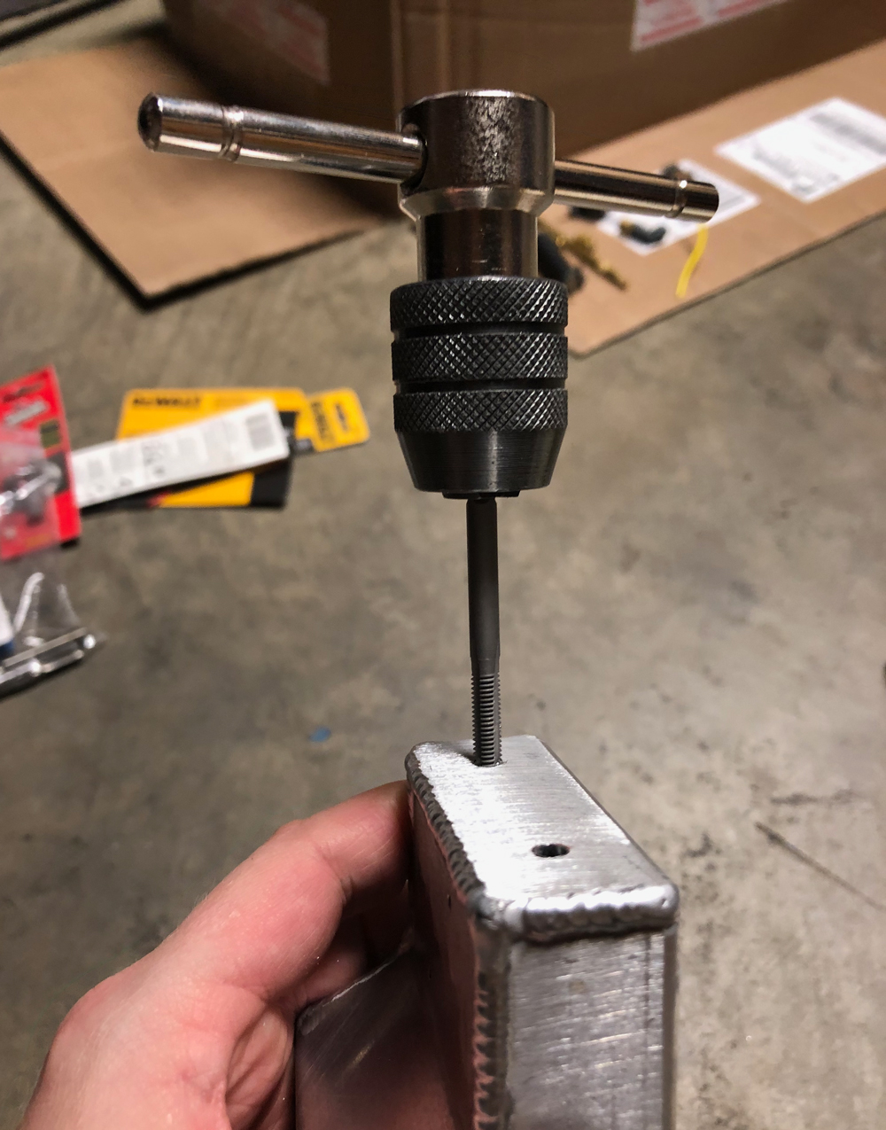
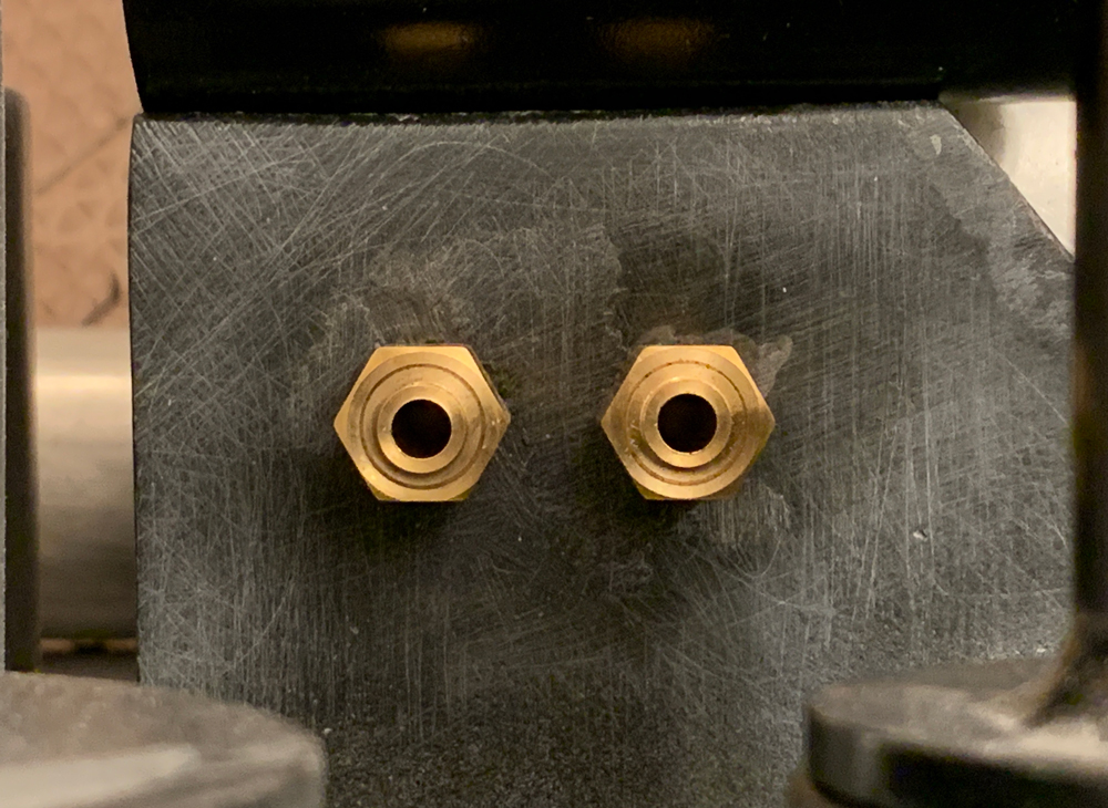
Next was the excellent GBFans aluminum HGA. Ever since working on the Freeky Geeky thrower, I had an itch to get more aluminum parts. The HGA originally had tapped holes in the Spengler configuration (I think). For mine, I wanted to line them up so I filled the holes with JB Weld SteelStik. I used primer to make sure I had these filled seamlessly. Then I flipped it over and tapped it again.

Clippard and replica Legris elbows screwed in

After painting, I used epoxy to attach a replica label from Freeky Geeky. I drilled a tiny hole in the center but there’s no screw.

My original ion arm was a sink discharge tube mounted on a cheese grater. I had replaced it with a resin arm, but it was time to upgrade again.

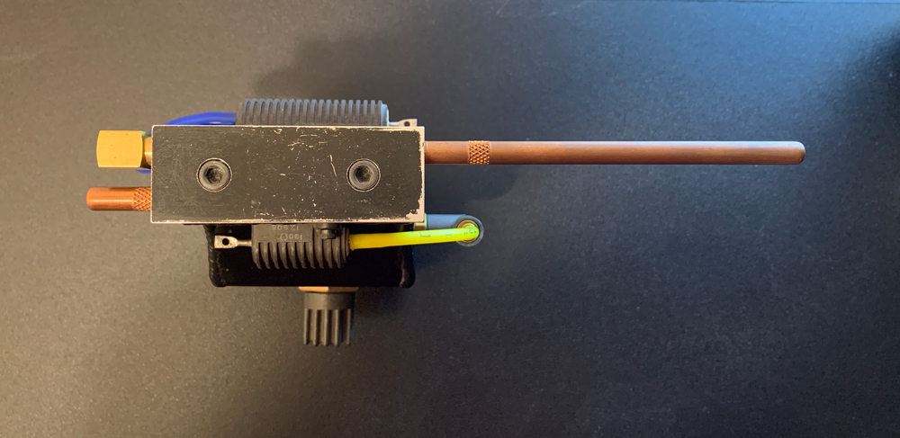
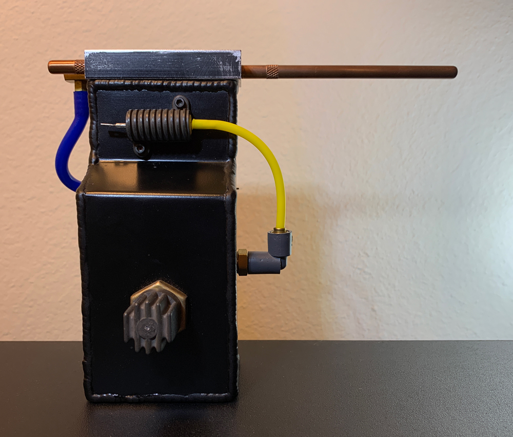
Concurrently with building the HGA, I worked on a new ion arm using an aluminum arm body and cap (with brass rods) from GBFans. I also purchased real resistors and used one of my Legris elbow replicas.

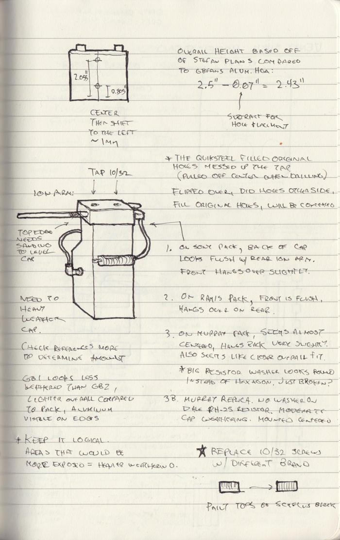
I painted the cap black (pre-weathering). I can’t remember if the arm was already tapped for the three resistors and elbow, or if I did that. For the larger Dale PH-25, I used a second brass ring as a nut inside the arm.

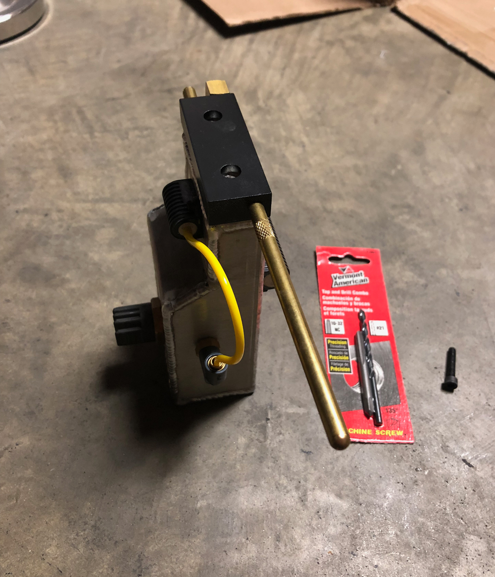
I tapped the arm for the cap. I sanded the top slightly, so that the cap would be level.

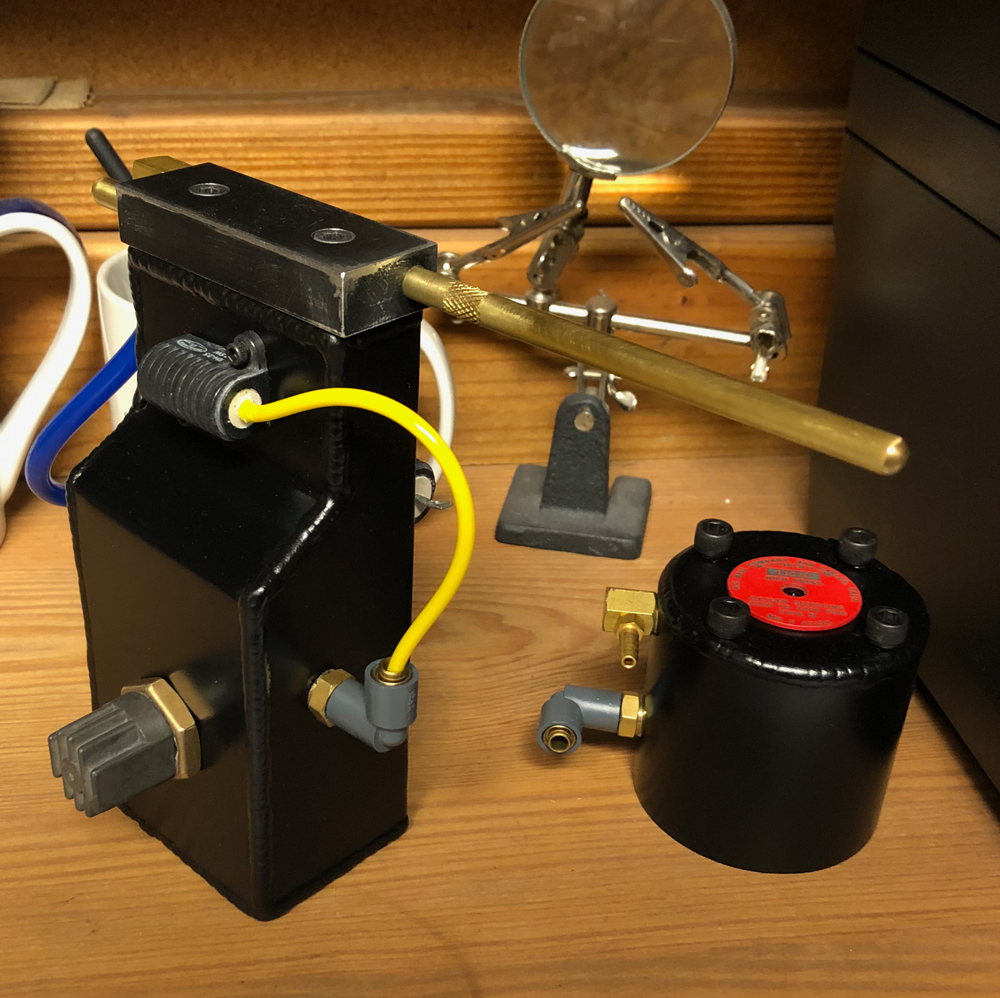
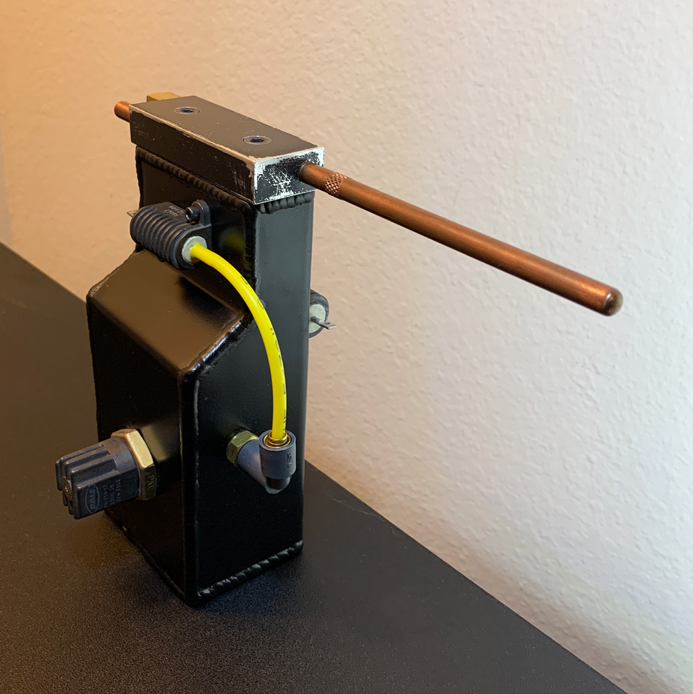
The yellow and blue tubing in the picture are temporary. I painted the arm and weathered the cap. Checking reference pictures again, I noticed (for the first time) that the real rods were not brass but copper. I looked for a replacement, but couldn’t find anything for sale that was as nice as the GBFans design.

I started to wonder if I could just make my own… Yet outside of this hobby, in my life on the real world, unsympathetic circumstances slowly manifested against me. Bad craziness and real wrath-of-God type stuff. And this was before 2020 started.

…

About a year later… I’m back (more or less). Now with very different circumstances, I had no idea how to start working on my build again. Eventually, I picked up right where I left off but got very obsessive about making my own rods with screen accurate knurling.

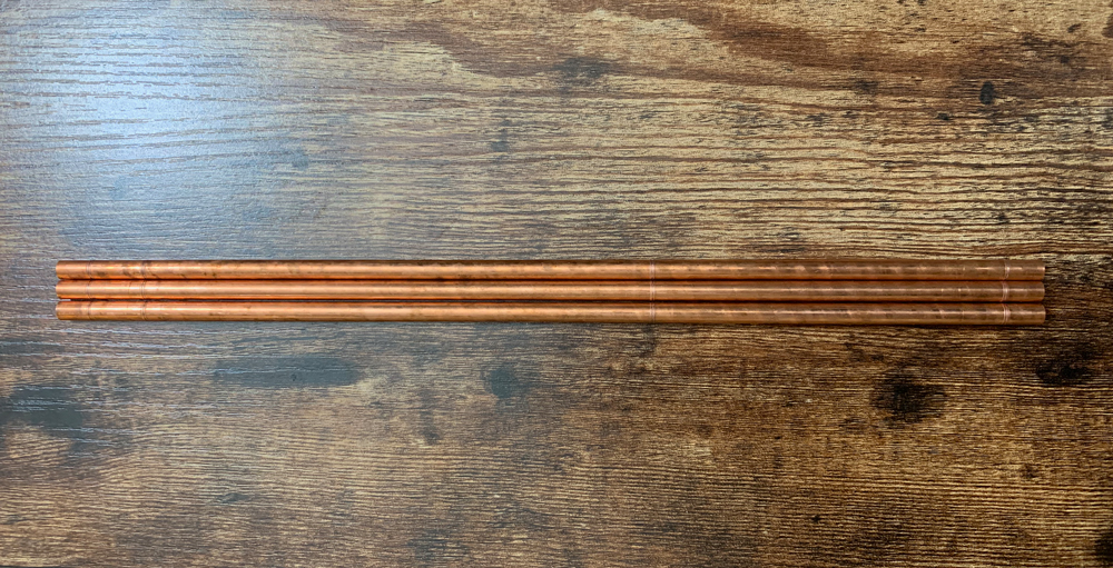
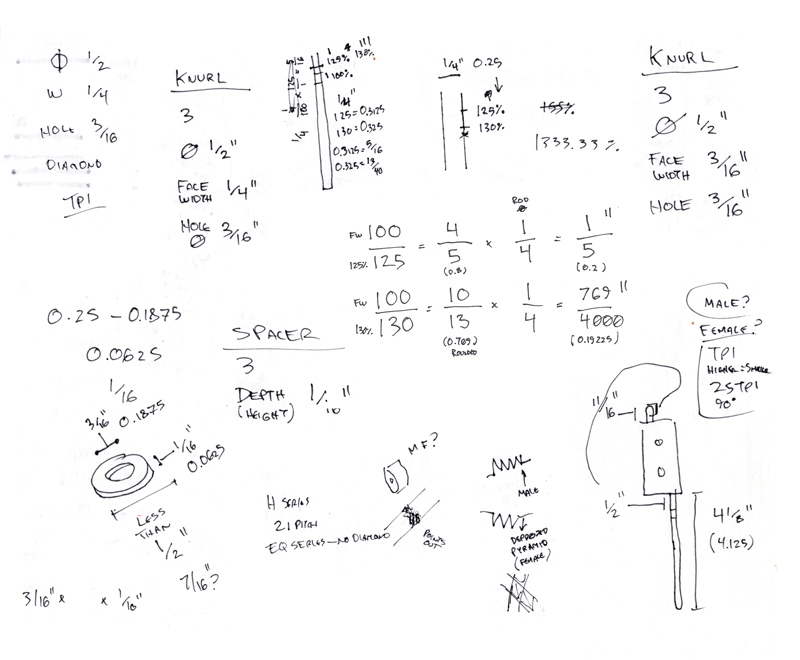
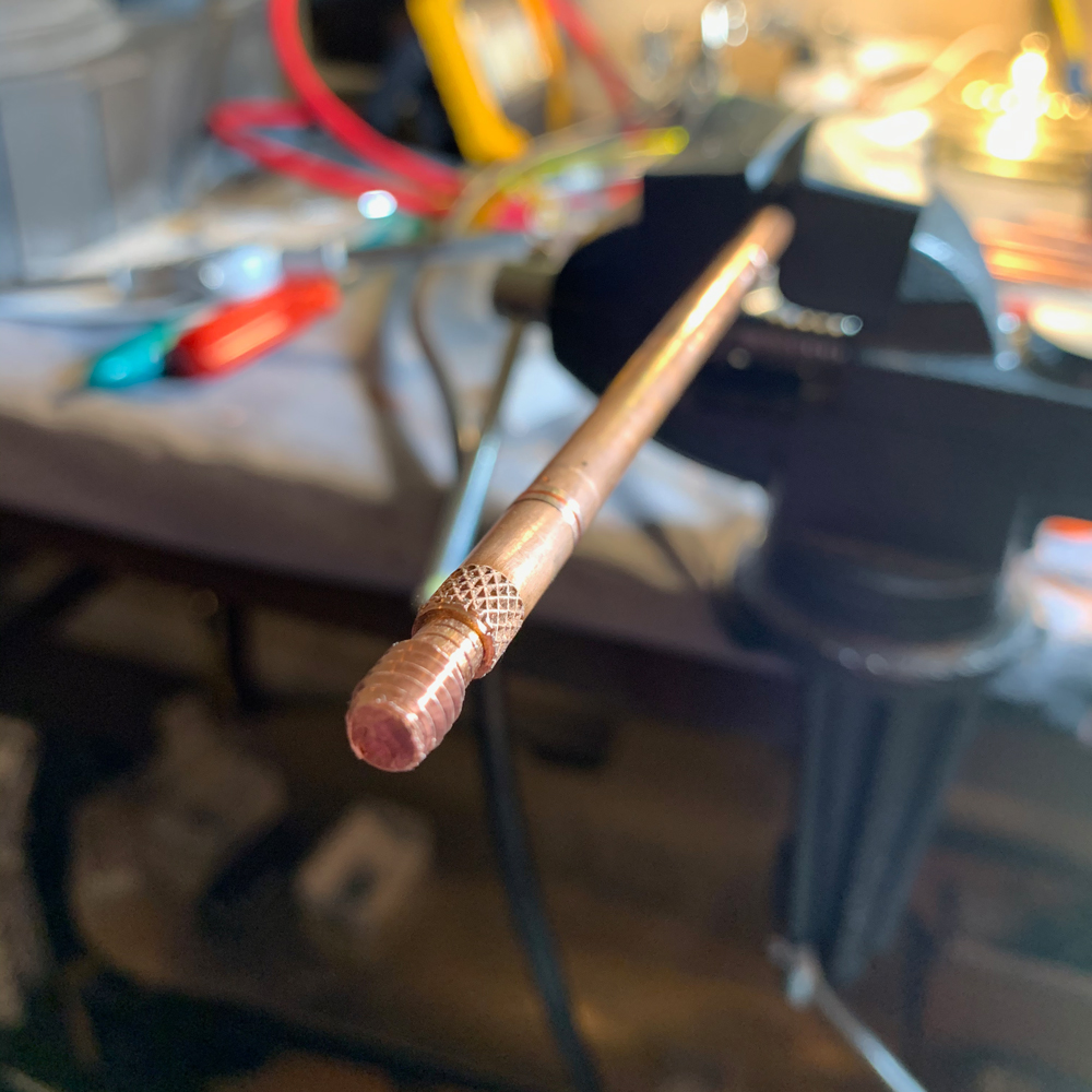
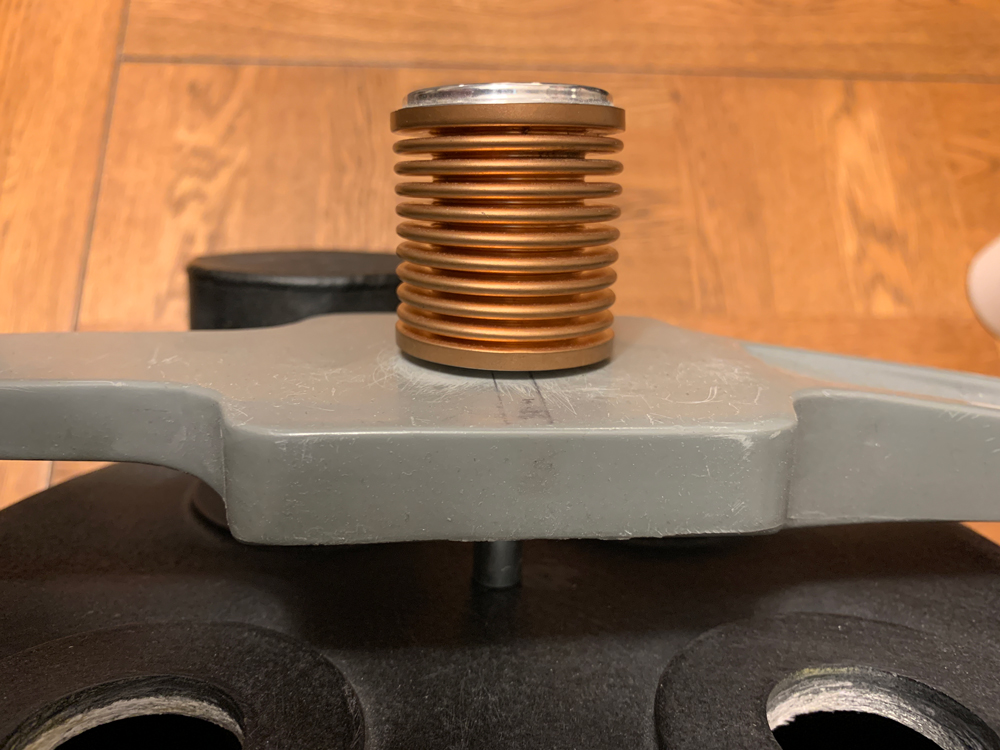
I wouldn’t be able to say if the values I used were correct unless I could get my hands on the real ones. Based on the reference pictures, I used 4 and 1/8” for the front rod length and 1/2” for the space before the knurling. On the rear nub, I used 11/16” for length and flush knurling. I used 1/4" as the rod’s diameter, which is consistent with other replicas I’ve seen and appears to match up with reference pictures. You can get copper rods of this size from numerous stores.

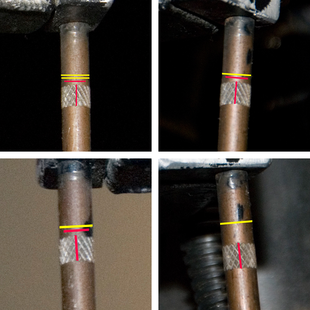
1/4" is also a common face width size for knurl wheels. At a glance, the knurling face width looked like it might match the rod’s diameter, but I thought it looked smaller. I decided to base my measurements on the Murray pack pictures taken by Demon Vice Commander. These have excellent resolution. I also thought that knurling on the other packs appeared similar.* On the pictures, I scaled lines to compare rod diameter (yellow) to face width (red).

**The Spengler pack clearly uses a different TPI (teeth per inch) on the rear nub and the front knurling looks like it’s either missing or obscured by black paint or oxidation. *

In three of the pictures, rod diameter was 130% compared to face width. In one picture, it was 125%. Keep in mind that these are fuzzy measurements, because of lens distortion, shadow, rod curve, picture quality, etc.

Apologies for the sloppy notes. Using 130% would make the face width ~769/4000", which is very close to 3/16", a common face width size (this would have made the difference 133.33%). 125% would have made the face width 1/5" which is not common.

Next, I compared pictures of 3/16" knurl wheels to the pack reference pictures to determine pattern and TPI (teeth per inch)—male diamond and 25 TPI. Of course, you can’t knurl without a knurler, and this is where it got tricky.

If you’re using proper machinery with a lathe, there are a lot of options. But there aren’t many hand knurlers to pick from, let alone affordable ones. Nearly all of the ones I saw were limited to a 1/4" face width, which may explain why this shows up on a lot of replicas.

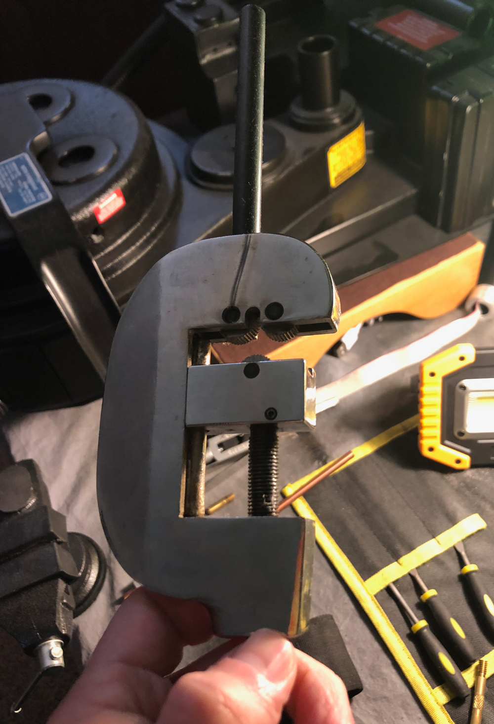
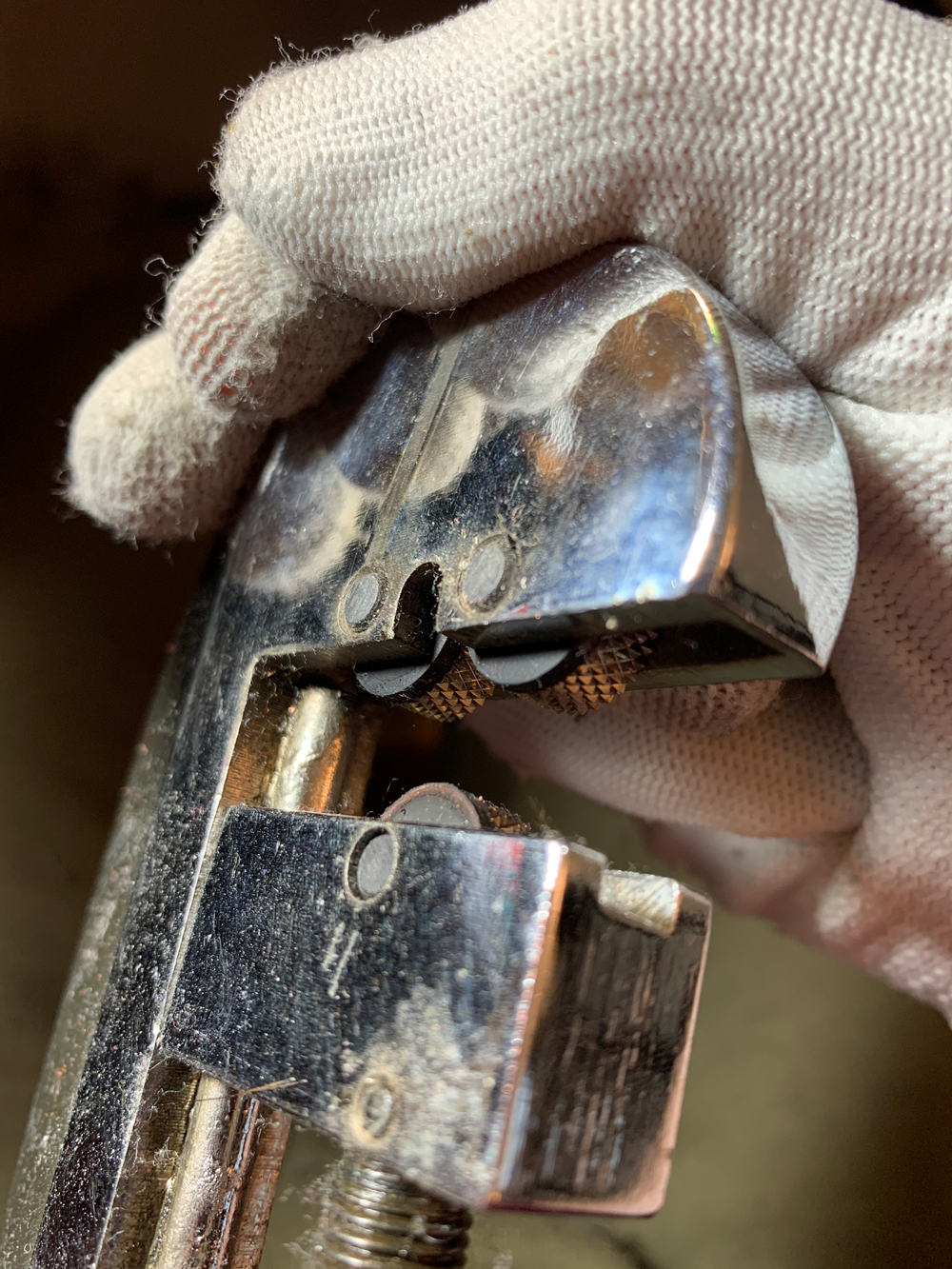
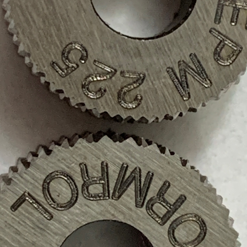
I had no idea if this would work, but I bought this hand knurler from MSC Direct, which came with 1/4" straight pattern knurl wheels (above picture). I hammered out the knurler pins and put in 1/16" rubber washers and the correct 3/16" knurl wheels.

I couldn’t get it to work.

I was about to give up when I noticed that one of my wheels was defective. The cut was just slightly off, but enough to mess up the pattern.

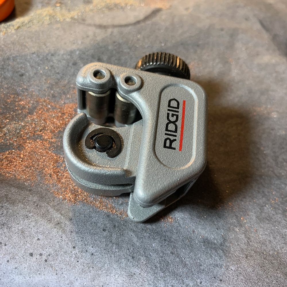
After getting a replacement, I was back on track. I purchased a tube cutter to cut up the rods, but also made small cuts to mark out my measurements. The small edge also helps with knurling and making grooves.

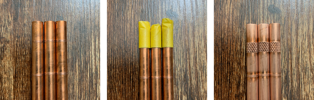
Not necessary, but I used tape to help with lining up the knurler, which tended to be difficult. I think I loosened up my hand knurler when I was messing with it, and had some additional wiggle. I always did knurling first, in case it didn’t turn out.

I knurled both the front rod and rear nub. However, on most of the packs, the rear nub doesn’t appear to be knurled. The nub on the Spengler pack does have knurling, but uses a different TPI than the front rods on the other packs. I knurled my nubs with the same pattern as the front. The knurling does serve a functional purpose, making installation easier (thumb grip). And it looks cool.

If the knurling turned out okay, I’d file out a groove so that the rod can be screwed in flush (based on the GBFans design). The groove can be cleaned up but it isn’t necessary. Next, I’d thread the rod end with a die. I found it to be a lot easier to chamfer the end first. If the threading isn’t lined up right, the rod will end up being crooked.

The rods are cut with the tube cutter.

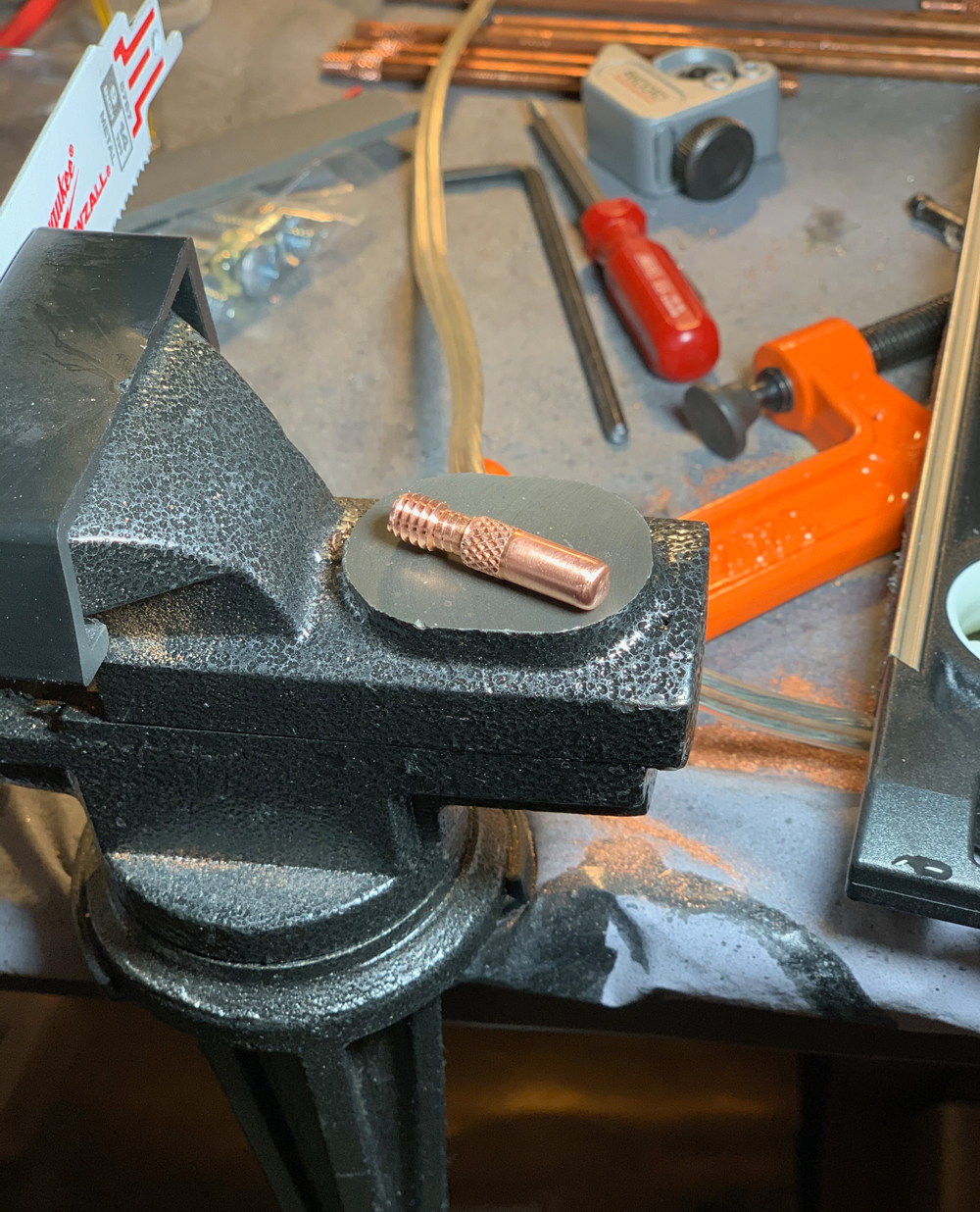
I then used a deburring drill bit to chamfer the rod ends. As mentioned above, this helps with threading the rod too. In the picture below, my aim was off a bit.

Most of the screen-used packs appear to have a filleted end, some cleaner than others. The chamfered edge is still visible on some. The DC Planet Hollywood and Spengler packs appear to have a more visible fillet. I prefer the clean, idealized look of the GBFans rod.

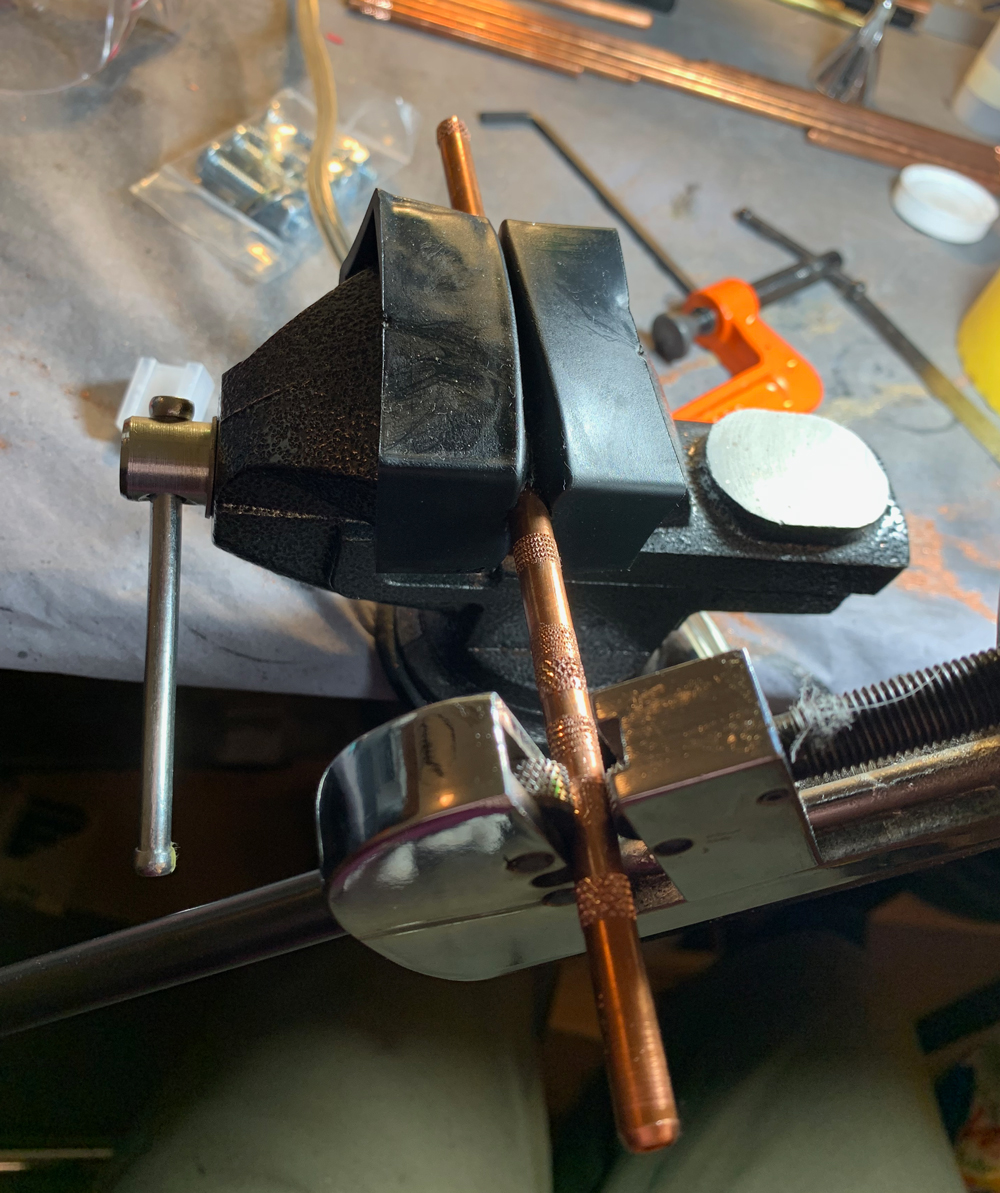
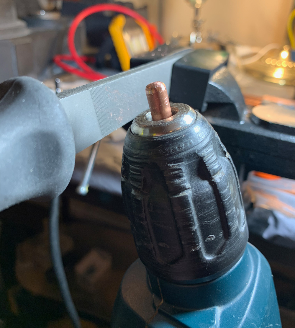
Making a fillet is a lot trickier than a chamfer. To do it right, you need an end mill specific to the fillet curve radius. And it’s not normally done by hand! This took me a moment, but my solution was to put a metal file in my table vise, put the rod in my drill, and just wing it.

**I bet you could find some rods that have already been professionally filleted and skip this part. Although, considering how rough the real ones look, it might be possible they did something similar to this.*

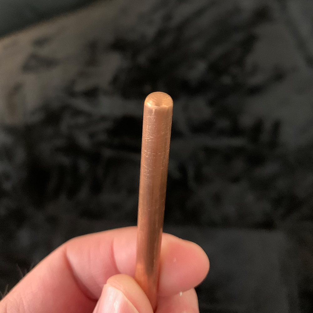
After getting the shape right, I used sand paper to clean the end up. I also worked on cleaning up other scratches and rough spots on the rest of the rod.

Once I had most of the scratches cleaned up, I did wet sanding with a very fine grit (2000 I think).

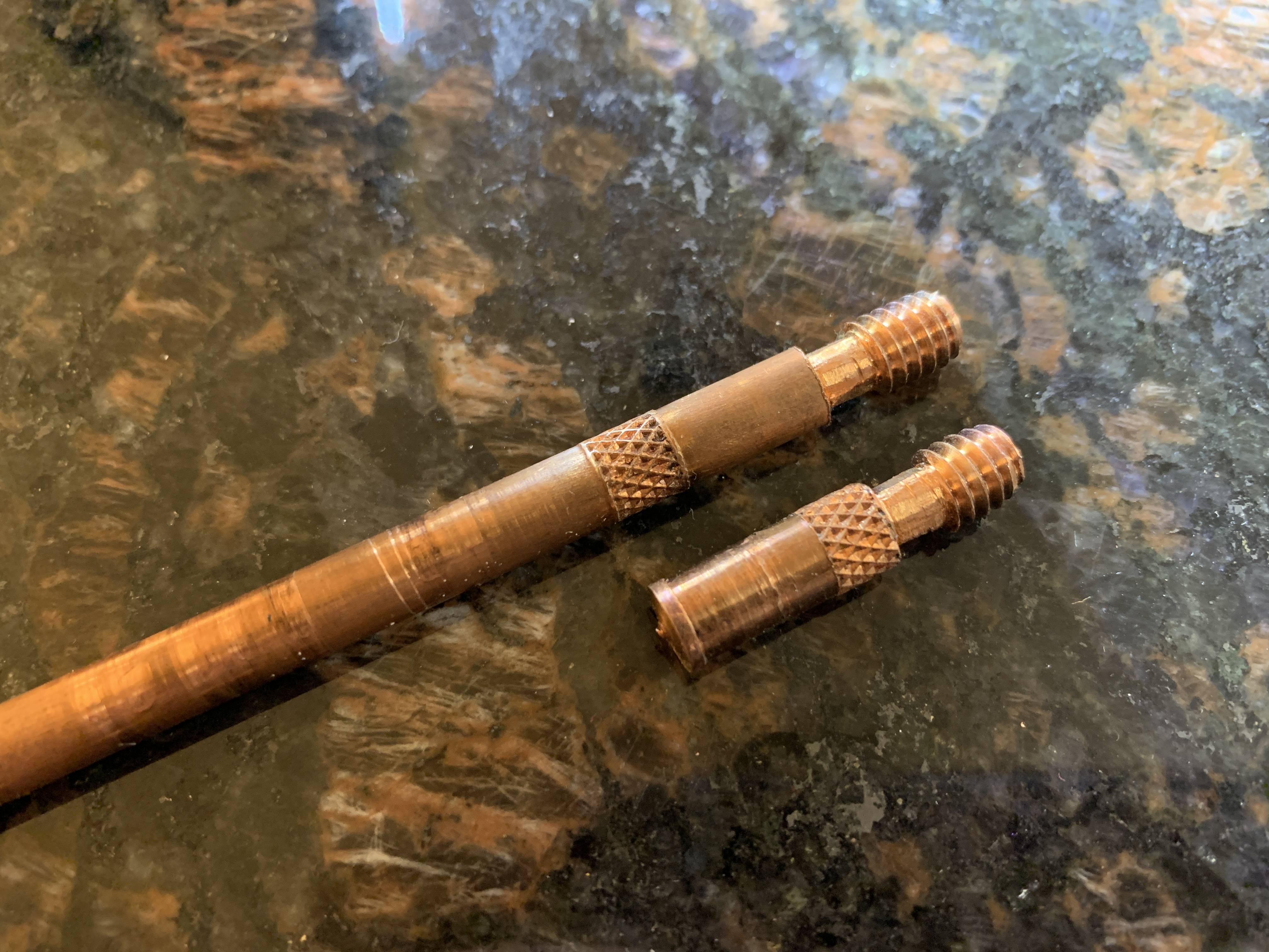
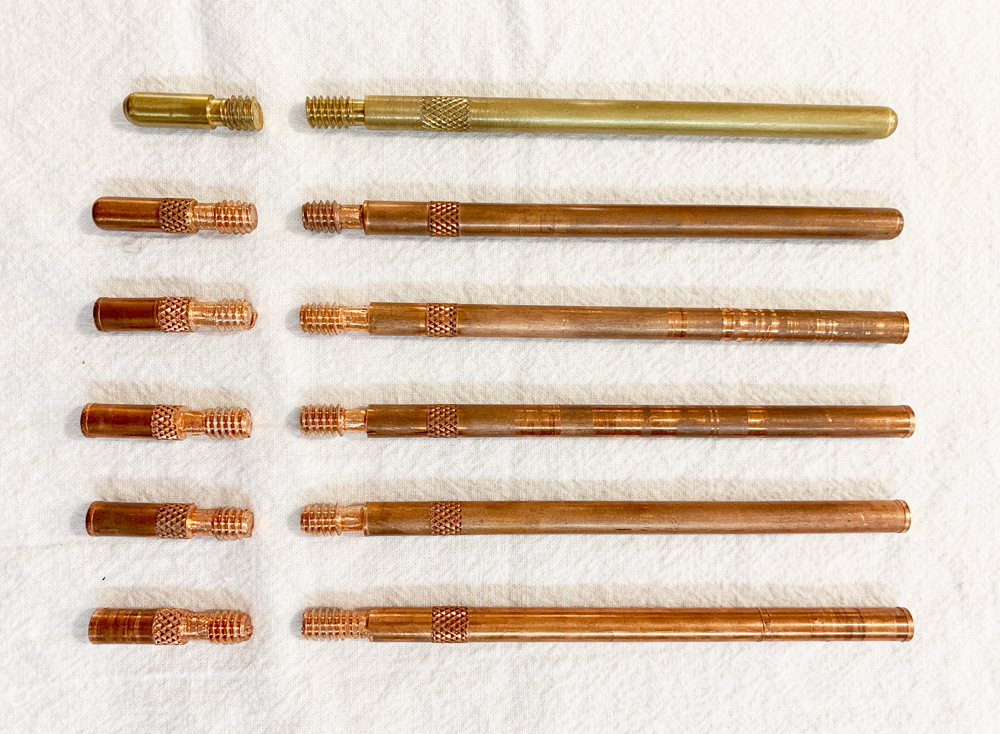
In the picture below, the first set is the GBFans brass rods. The second is my finished set. The others are mostly completed rods that still need to be chamfered, filleted, and cleaned up.

On the front rod in my finished set, the distance between the threads and knurling pattern ended up tighter than 1/2" so may I replace it later. However, the DC pack looks like it’s less than 1/2" so I don’t think it’s a big deal. I could also make the end messier like the real packs, but for now, I prefer the idealized look.

With the right equipment, the rods would have been much easier. But for me, improvisation was part of the challenge. I was successfully pulled back into the build.

After installing the rods, I added yellow 5/32" (4mm) Legris tubing. If I can get my hands on some, I’ll replace it with Nycoil. The 1/4" blue tubing is generic. I think it’s supposed to be Clippard, so I’ll be on the look out for that too. I kept the blue tubing a bit shorter like the Murray pack in GB1.

Essentially complete. Later on I will need to blacken the rods, do a little more weathering, and some more painting after the infamous ugly weld. This is a small detail, but I also want to paint and weather the tops of the 10/32" socket head cap screws.

Links in this post may be affiliate links. Purchases made through them help support this site at no additional cost to you.

I had modified my Exoray bumper to fit my older resin shell and needed a replacement. I looked at a few replicas, including a production lineage cast. Eventually, I chose the Crix bumper. The quality is excellent and it’s exactly what I wanted: idealized and clean but still looks accurate.

I measured out exactly where I wanted everything to line up. I drilled the side bumper/shell holes together, but I drilled the center holes separately. The holes probably wouldn’t line up perfectly, but I found that I usually got better results whenever I had to fix something.

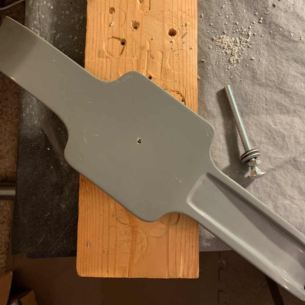
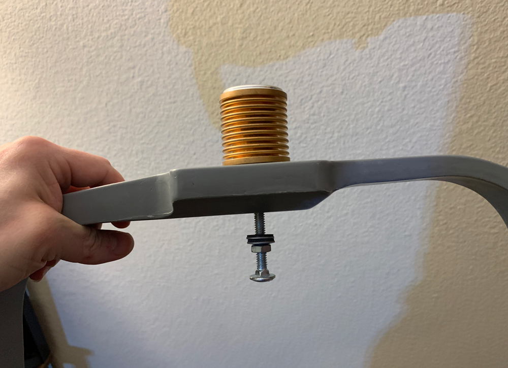
Here’s the bumper (with the beautiful shock mount from GBFans). It’s hard to tell in this picture, but the carriage bolt is slightly crooked.

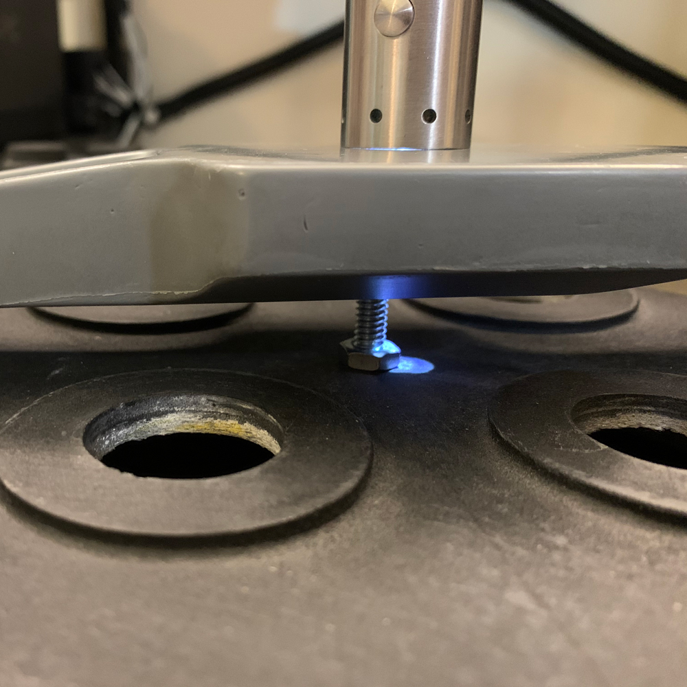
Easy to fix—JB Weld SteelStik and re-drill—but a little tricky to line up. I made the bottom bumper hole wider to get some wiggle room. I used a flash light to find the right angle. This also showed that the center hole positions wouldn’t match even after the angle was fixed.

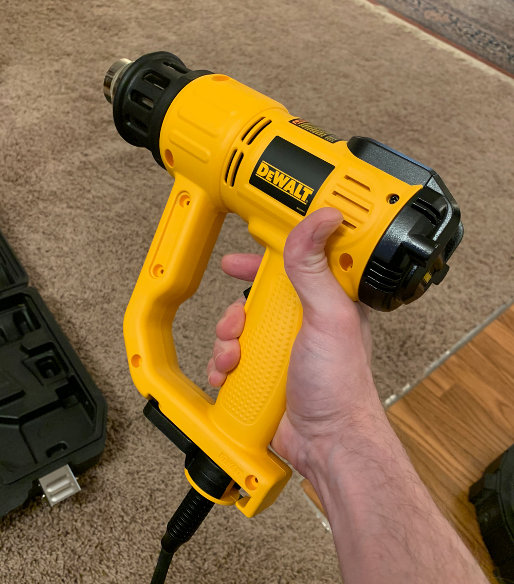
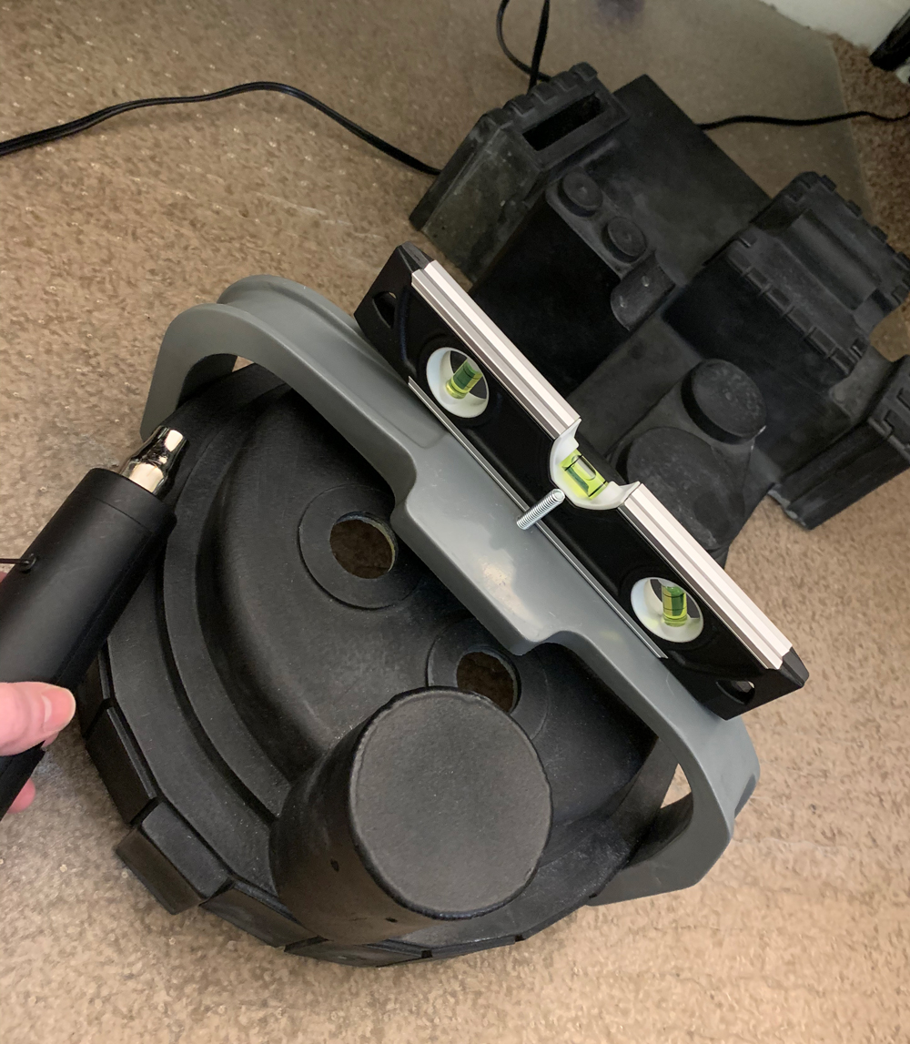
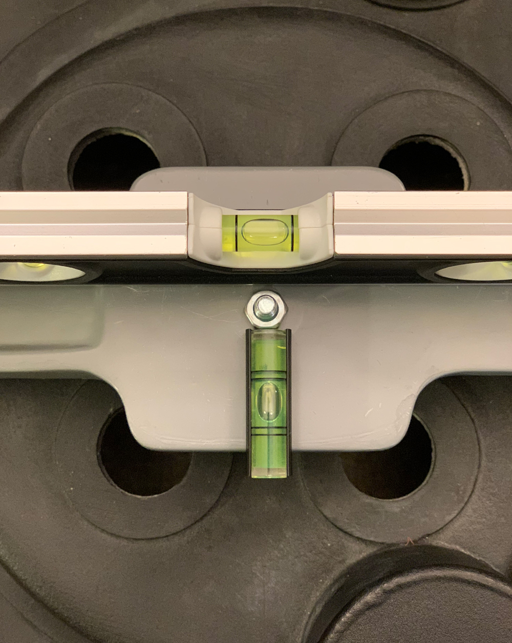
With a level, I could see that the bumper was sitting at a slight horizontal angle. I got out my heat gun to adjust the bumper shape.

The Crix bumper was way too tough for my cheap gun, so I got out my BFHG.

I heated up the bumper and held it in the position I wanted. I did this a couple times and it lined up just right. This also improved the overall fit of the bumper to the GBFans shell.

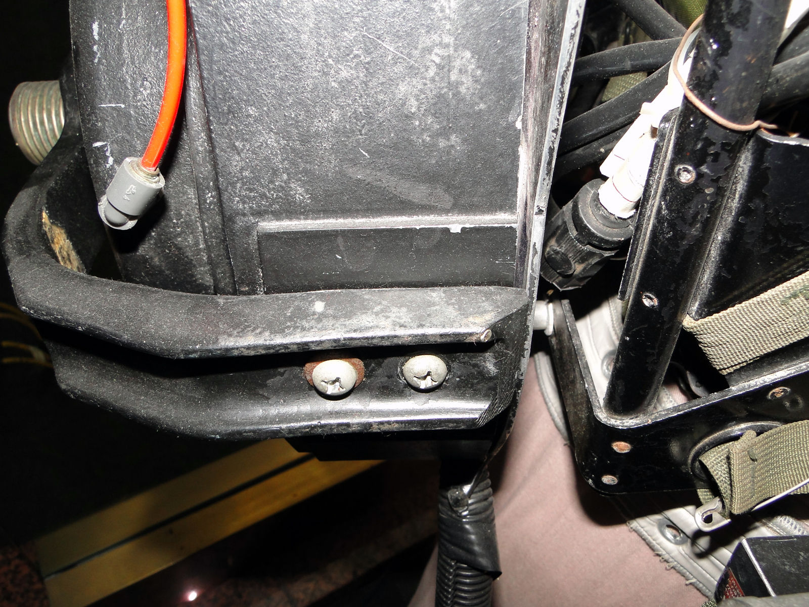
If you’re doing a GB1 pack then it doesn’t seem that the bellows had a screw all the way through the bumper and into the cyclotron.

Thanks! I should’ve shown this.

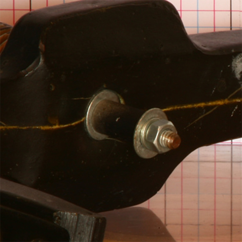
I’ve got the carriage bolt attached from the inside of the shell, through the bumper into the bellows. There’s also a steel spacer in-between. Is that right for GB1? I’ve seen that done in other GB1 builds but I’m not completely certain. It’s sort of the opposite for GB2 packs, but there are a lot more references of the actual packs that show that. I can still fix mine.

The thinking changed on that less than a year ago. It looks like the bolt was only through the bumper and didn’t bridge the gap to the cyclotron at all. Possibly changed to increase the bumper stability for GB2??

Wow, I completely missed that. Thank you!! Easy to fix. I just looked over a discussion on this in Mburkit’s incredible Omni Pack Build. It’s got the 4K screen cap where you can see the bolt head on the back of the bumper.

In the GBFans reference section for the screen used bumper, there’s an inset hole on the back of the bumper with a washer inside.

This is after it was modified for GB2, but I’m wondering if it’s possible that they had something similar for GB1—just the inset hole and washer for the bolt head to tighten against. What do you think? Of course, unless someone whips out a dental mirror, no one’s going to actually see this but I thought it might be cool to include.

Just a heads up on that check out 1984 Proton Packs Finished

if you check out his pack picture with his cyclotron removed he had built his bumper with no bolt all the way to the cyclotron,

Now I’m not saying that makes it true but I do believe he was vary methodical when he made his pack and I do believe the 84 packs did not have a spacer or bolt that went all the way. His reference pictures are panful to look at when it comes to this one spot. 1984 Proton Packs References

I will WARN you not having that long bolt supporting your bumper can lead to sagging of the bumper over time. It will also sag if it is over heated in sunlight on a vary hot day. I know taking a heat gun to your bumper is no fun once you have finished it and then you may have to repaint it.

The bolt from the bumper into the shell was a GB2 mod. Stuart provided some screen grabs in his build thread that show no bolt connecting the bumper to the cyclotron in GB 1.

It’s a matter of preference though. I kept the bolt running through the cyclotron on my build because I wanted a little bit of extra strength for the bumper. It’s really not noticeable and aside from the accuracy buffs like us the average person would either never notice or be none the wiser. So it just depends on what you’re looking for in your build.

Thank you both! I’m definitely convinced on there being no hole through the shell for GB1. I worded my last question awkwardly (middle of then night). I was thinking about how the bolt head should look on the bottom of the bumper.

I do like the added strength. I think I’ll try out the GB1 setup first to see how sturdy it feels. I’ve still got a little more to post to get this build caught up, but will circle back to this.

I’m going for a semi-idealized GB1 hero pack, with a mix of pack details. I’m not recreating a specific pack, but want it to look okay next to the others, like it were a fifth “Petzrick” pack. I want a lot of the imperfections from the screen-used packs, but I also want to finesse areas that bother my OCD.
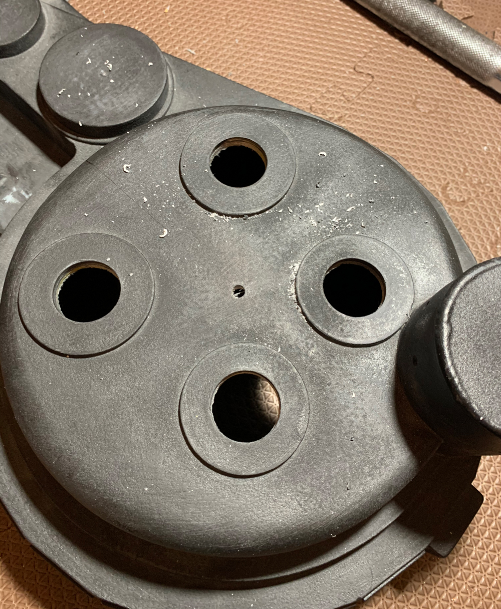
I went back and forth to working on the shell. The GBFans shell doesn’t really need much work. Mine had some clean-up areas, a small MB gap, and some minor warping. I also wanted to redo the power cell window and make some adjustments because of personal preference. And of course, I would need to fix my own mistakes.

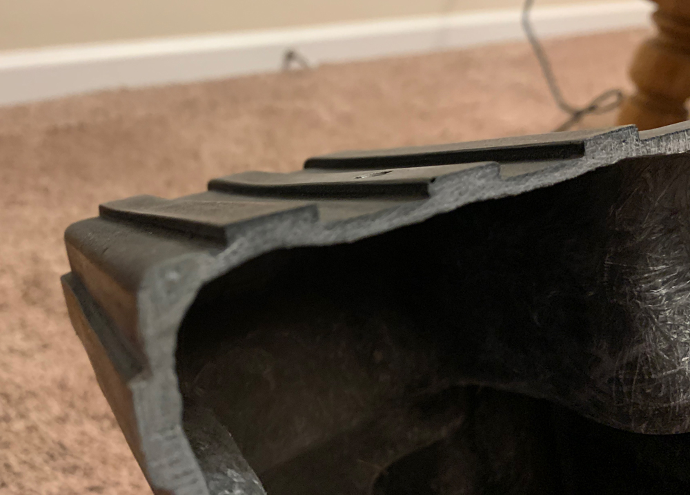
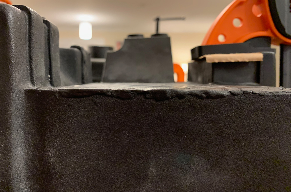
I had seen a recommendation and a warning against doing this, and should’ve paid more attention to the latter. To try and fix the MB gap, I did some sanding on the bottom edges of the shell. This helped, but took off a little too much in some areas. I was able to fix those later on, but it was tricky.

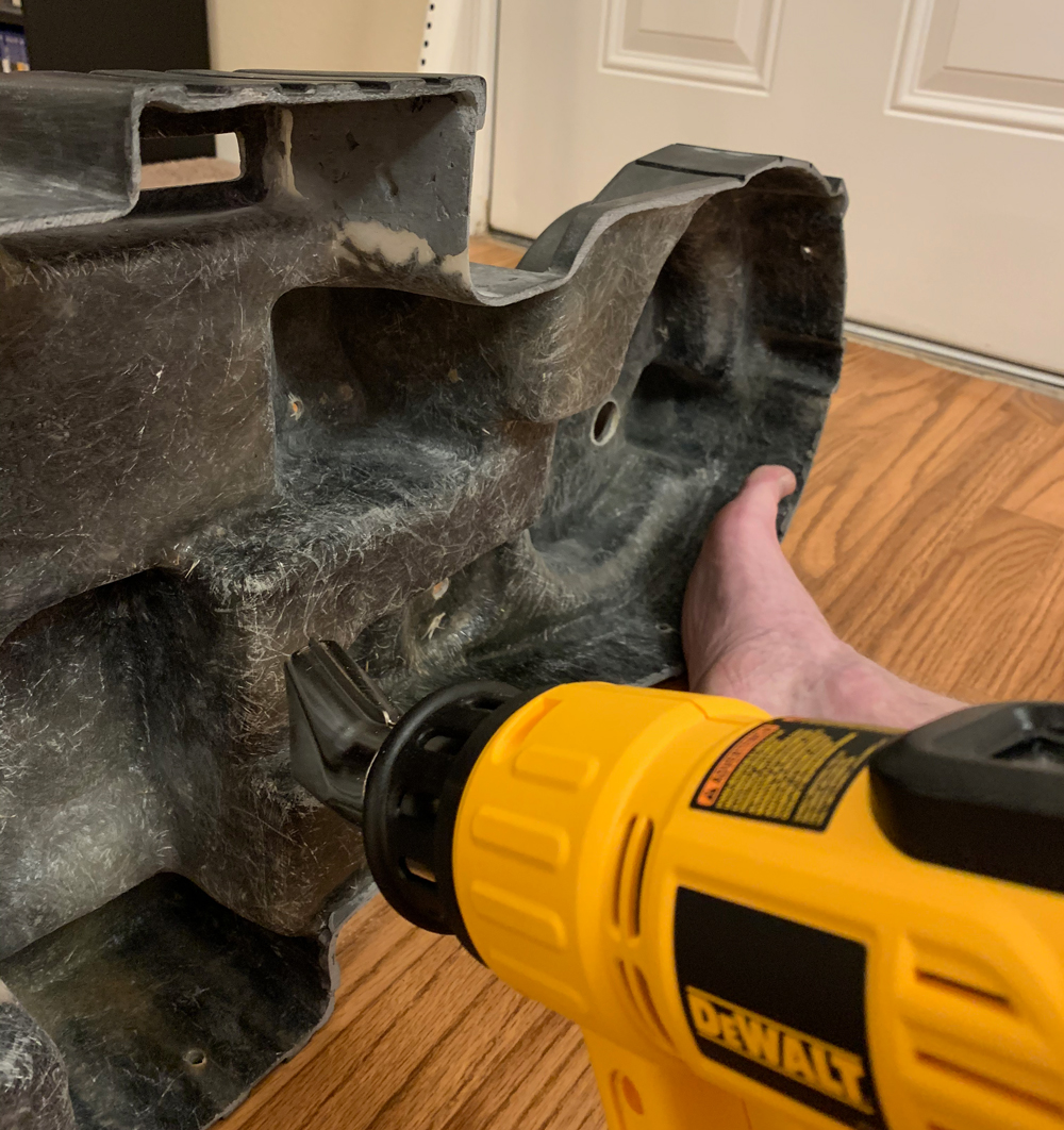
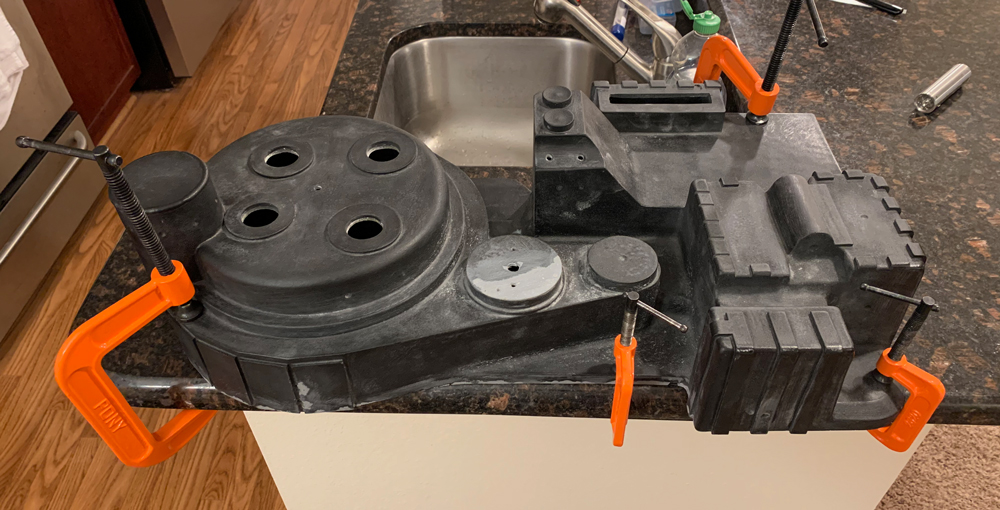
I had doubts about this, but I used my heat gun and got better results. I’d get the fiberglass really, really heated up, hold it in the desired position, and repeat a bunch of times. For the thinner areas this worked without problem, but thicker areas tend to go back overtime. I’ve read that fiberglass cells have a long memory.

Here’s fixing some slight warping on the gun mount. The heat took most of it out and I was able to fix what was left later on.

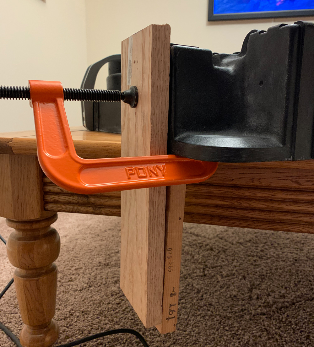
Getting the shell to lay flat was tricker. I got into a habit of re-heating the shell after I stopped working on it, and leaving it under clamps. This seems to have worked. It’s been unclamped for months at a time and has stayed flat.

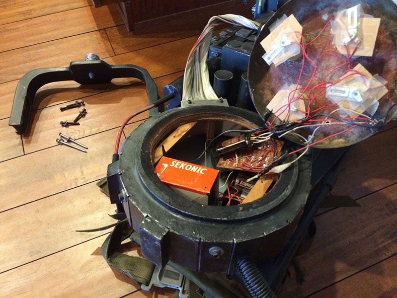
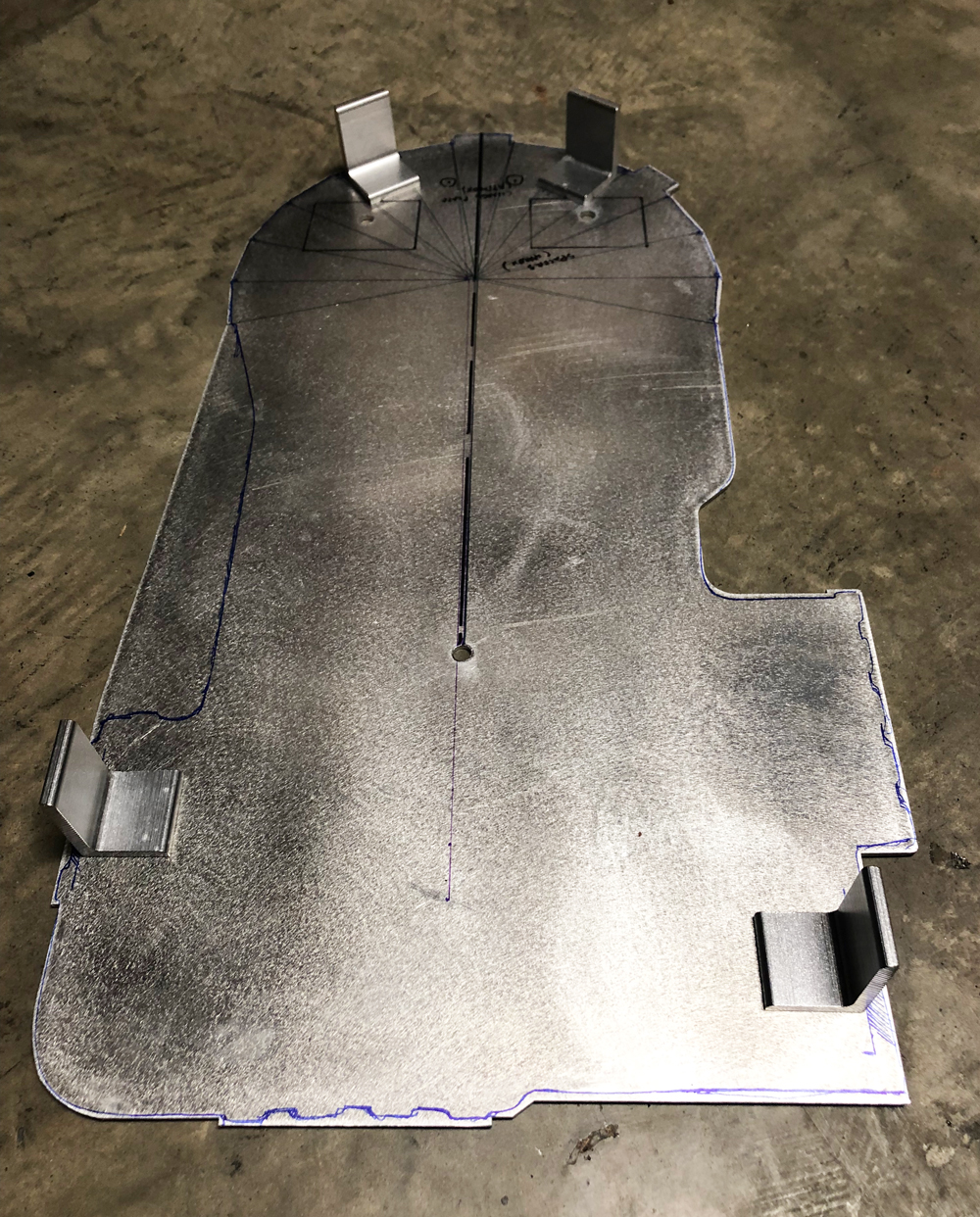
This was the second time I’ve mounted a shell to a MB, which helped. I did have an issue with my placement of the top left bracket, but fixed it later. I used steel rivets instead of aluminum, because some had gotten loose on my previous MB.

**The GB2 side screws on the bumper are just there temporarily.*

On the subject of the bumper I noticed in one of the Sony Lobby Pack pictures Number 285 That it has a wire or rod molded in to it and now I am convinced it was done to add support to the the part.

It is something I’m thinking of adding to my bumped to add support to it and that would help the bumper not need to have a bolt and spacer to the cyclotron.

What do You all think???

You can also see the wire really well in Demon Vice Commander’s pictures of the Murray pack. I’ve seen the wires recreated in a couple builds. Just saw a cool one recently and am looking for it.
For my bumper, I opted for idealized. If I were doing completely accurate, I’d try to add the wires.

EDIT: Here we go. RedSpecial added wire to the bumper in his build. Really nice build!

Some sanding was needed, but mounting the HGA was mostly painless.

For the injector tubes, I sanded out the sculpted-in plate on the shell first. I also needed to fix some damage I did to the bottom rib.

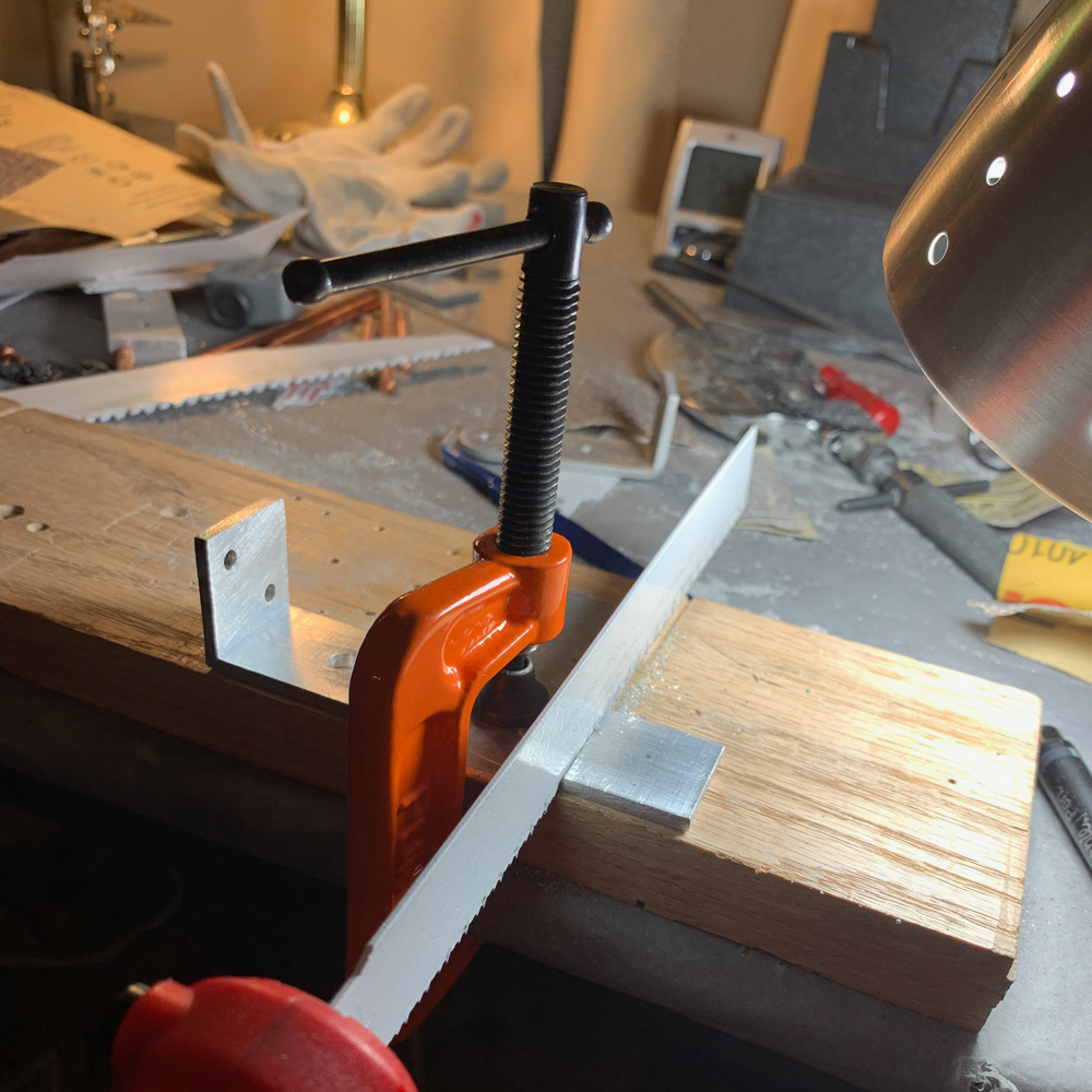
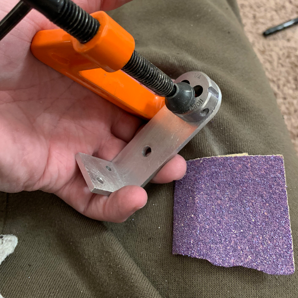
This time, I wanted to mount the L bracket at the same time as the tubes. After measuring, I made one out of a 1/4" aluminum corner.

This post helped with overall placement of the tubes. I have the front of the tube plate 1/8" back from the front of the power cell. I also wanted that odd angle and gap under the plate that some of the packs have. Having the bracket helped, but it was still tricky to get it lined up.

After figuring out where I wanted everything, I made a removable wedge, then drilled.

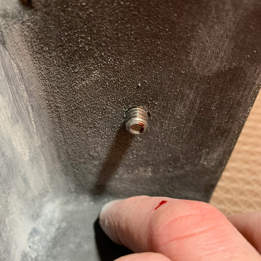
I used socket head cap screws temporarily on the bracket.

Compared to some other packs, I’ve got a little more space between the right edge of the tubes and the left EDA wall. A little of this might be shell variations but I also sanded the left edge of the plate slightly so that the right edge of the tubes didn’t go too far past the power cell. This area is mostly covered by the ribbon cable so I don’t think it will make that much of a difference.

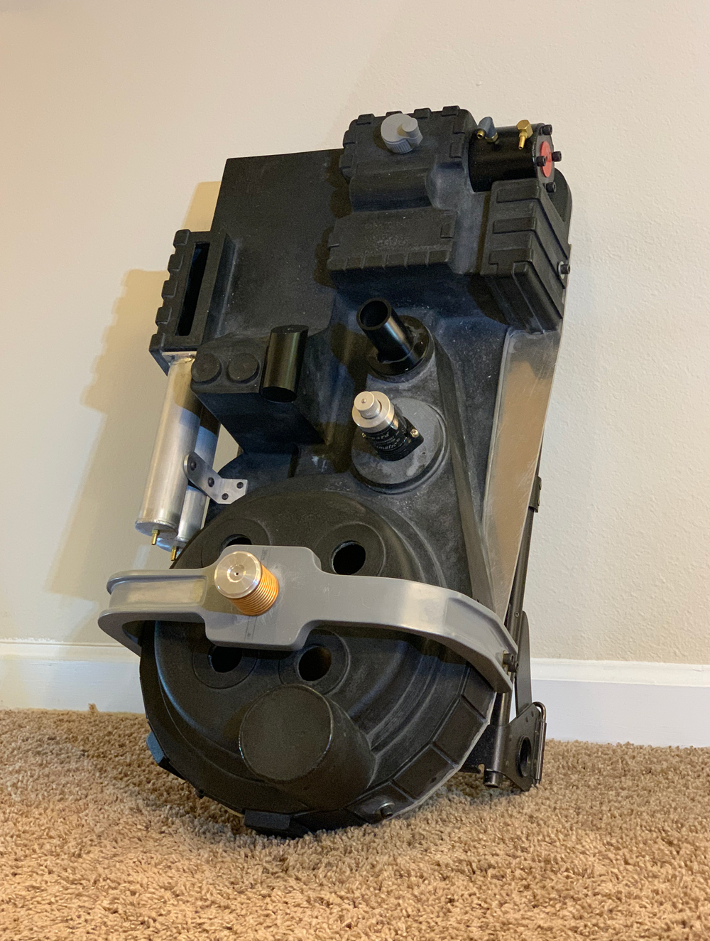
I also added the vacuum tube, PPD, and crank generator knob. I had already painted the PPD but I think it needs some detail work.

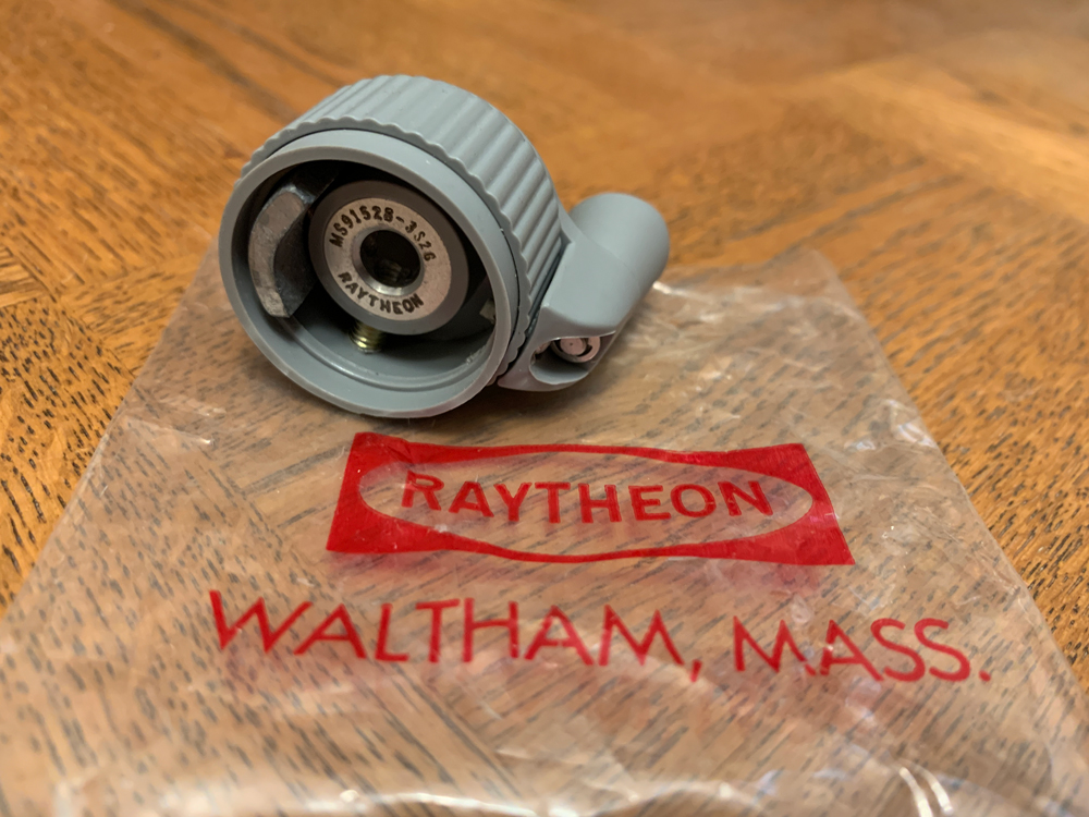
For the knob, I was able to score a genuine Raytheon.

This might cause some cringes and a skipped heart beat or two. For some of the shell adjustments, I built up thin layers of Apoxie Sculpt, sanded, built up more, sanded, etc. I hesitated to do this at first, but seeing Bishopdonmiguel’s All-Fired Plain-Vanilla Pack Build really helped show what could be done.

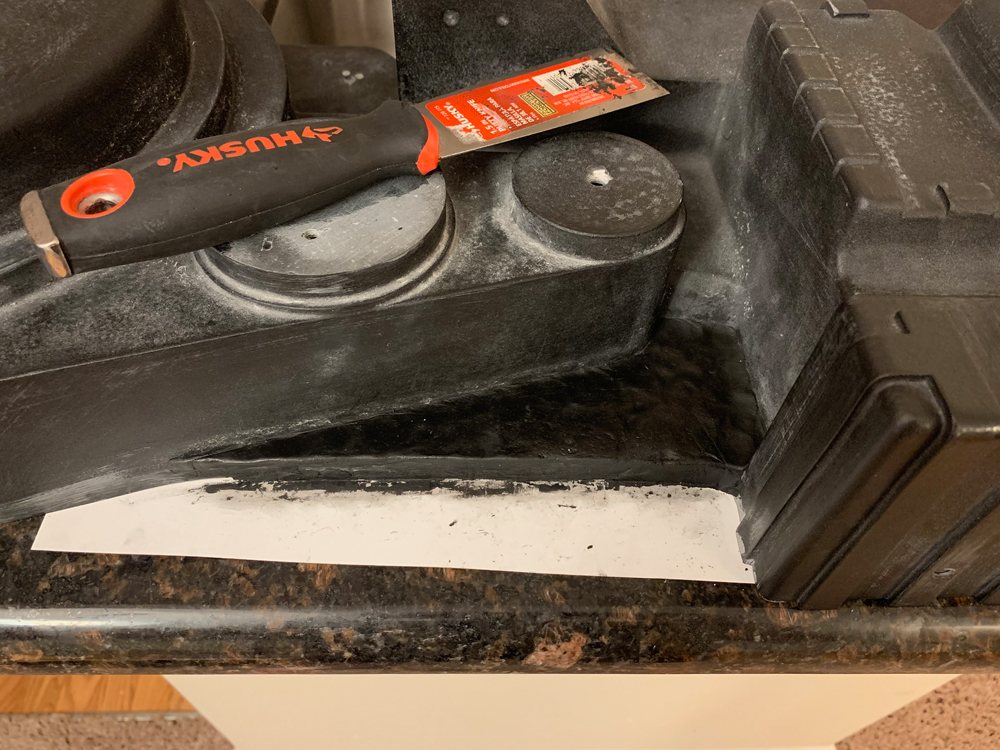
Both the left and right step-down spacers on my shell had a slight inward warp that I wanted to level out a bit. These are also the areas that got messed up when I sanded the whole shell earlier on.

I wanted to flatten the EDA surface to help with mounting the ion arm and booster tube. I also started to fill in the power cell window so that I could recut it.

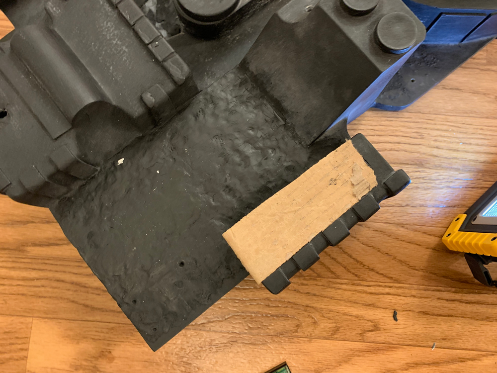
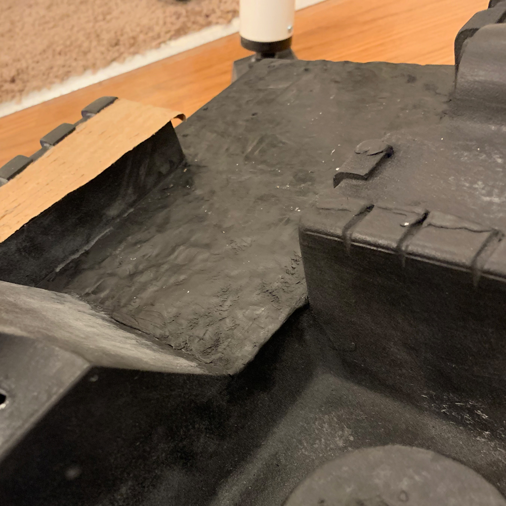
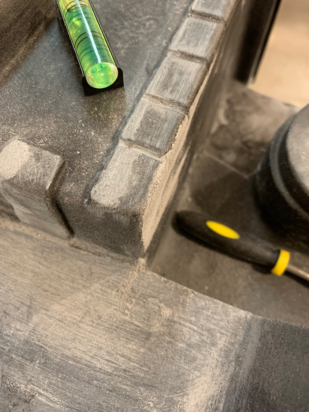
I wanted to reshape the bottom left corner of the gear box—sort of like an upward tuck. If you look at the corner in the picture below, I’ve added some Apoxie Sculpt to the tops of the ribs in that area. Basically, what I take off the bottom is going to be replaced with what’s on top.
Here’s after I’ve done initial sanding and “moved” the ribs. I’ve also reinforced this area on the inside of the shell. Later on, I will need to add the seam lines back that go across the bottom of the box.

Here’s after several rounds of adjustments. Very dirty and there are small surface defects all over the place now… I will be fixing each and every one of them.

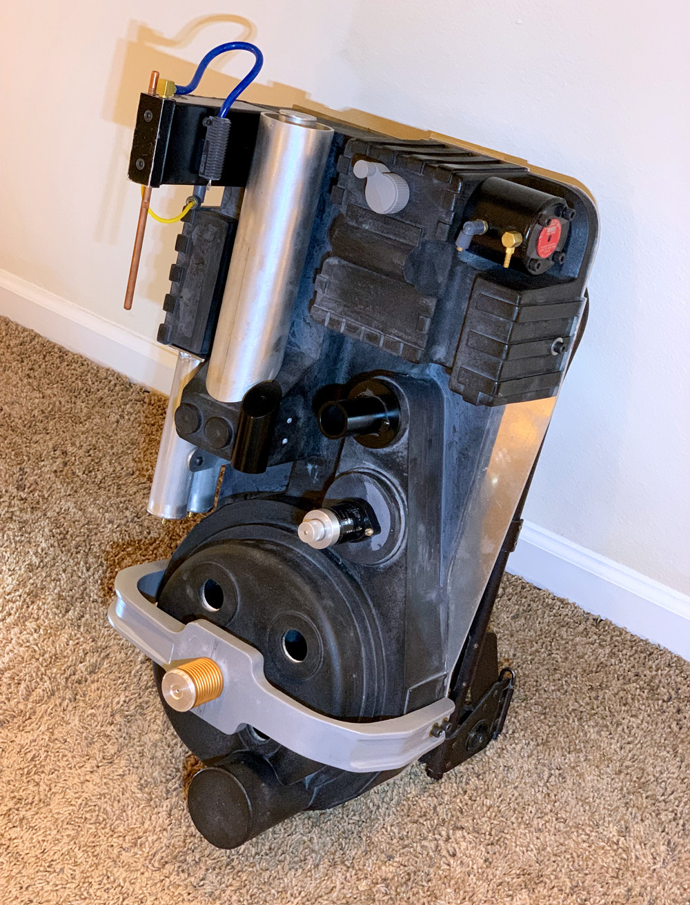
Still more to work on, but I had leveled the EDA to the point I wanted. Next I attached my Freaky Geeky booster tube and GBFans ion arm.

I did them on my build recently too. You can see striations along the angled face of the bumper arm that looks like it may have been sawn, and I added those as well.

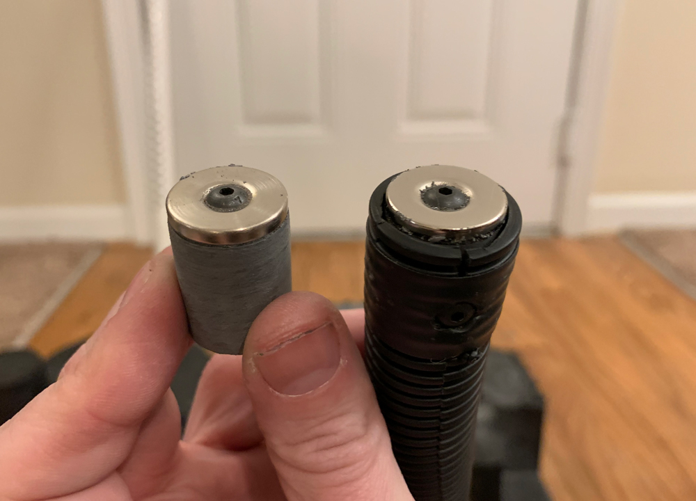
For the vaccuum hose, I wanted something similar to Bishopdonmiguel’s MagSafe Vacuum Line Gearbox Connector. I had a bunch of donut magnets from a past non-GB project, which I screwed into plastic dowels (instead of using epoxy).

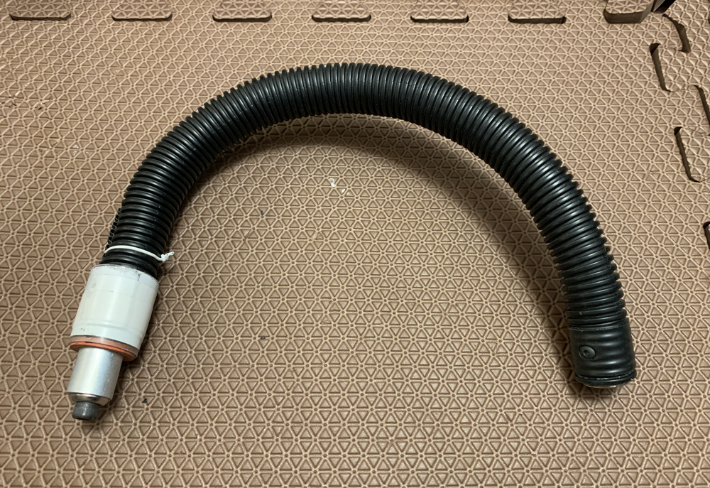
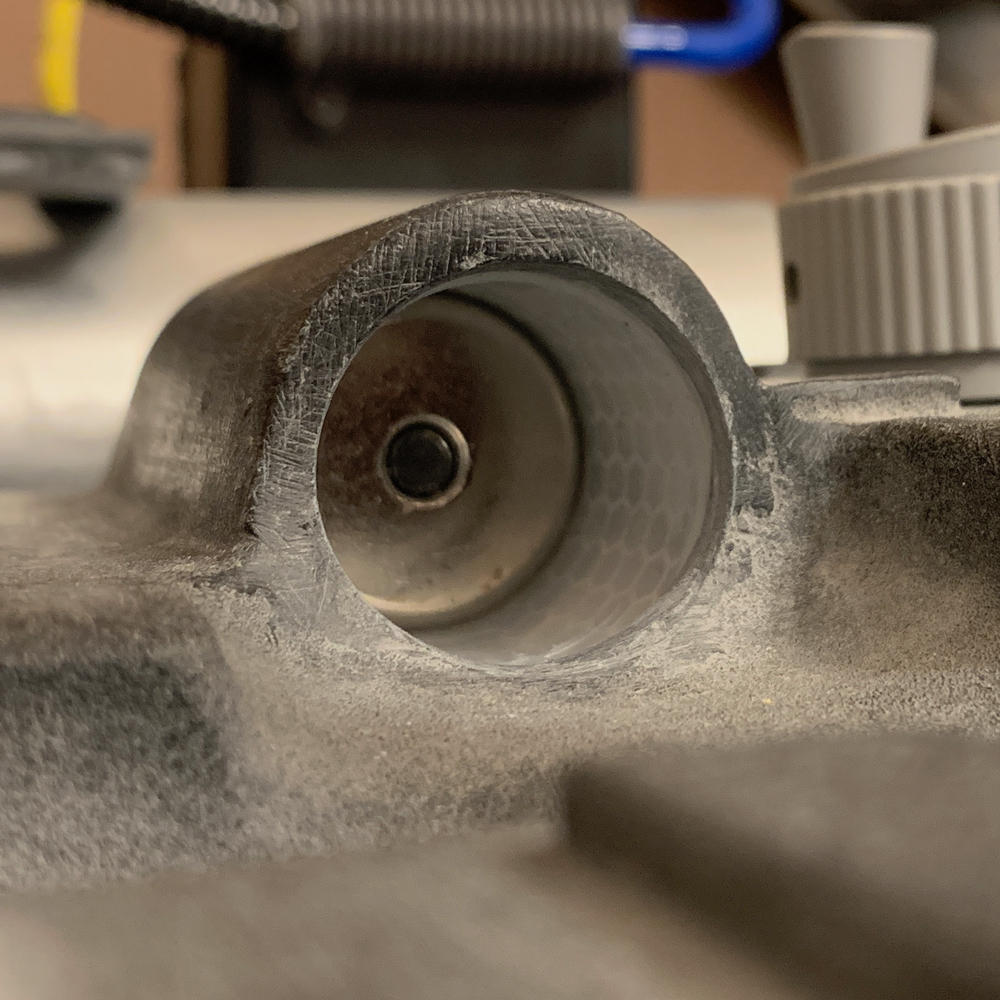
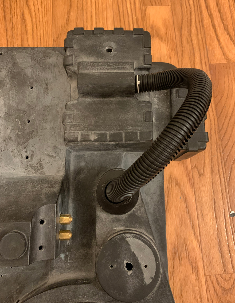
The white thing is a vacuum port that I made out of a SteelStik tube, and some washers and spacers. The white twisty is a reminder to add the steel wire twist later on.

Here’s a test fit. I haven’t attached the port to the inside of the shell yet (it’s just hanging loose) so the split-loom should lay flatter at the top when it’s done. However, I want to redo the split-loom because I got it bent up in a weird way while messing with it. I saw a tip recently that I want to try—straighten the loom out, hold it taut, and then apply a little heat.

I also installed the straight connectors.