Travis' Proton Pack Build Log - TC3.0 Thrower/GBFans Shell

Lots of thrower work - she’s coming down the finishing stretch! I got a little busy building and did not keep very good documentation, though… Oops >_>.

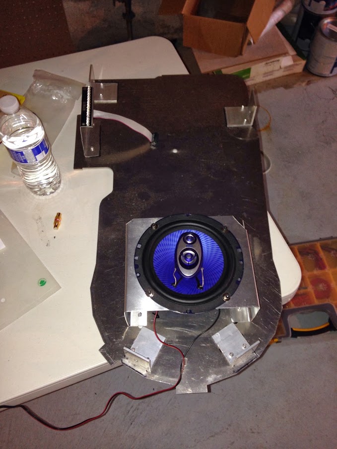
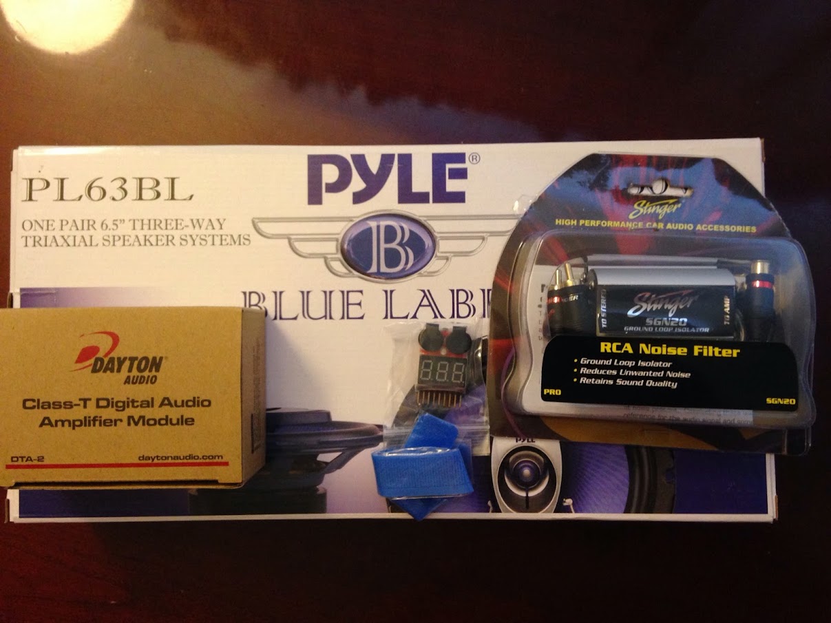
Got the majority of my sound stuff in. I’m going to use the Dayton Audio DTA-2 at the recommendation of Grand Wizard Julz, who’s build is a constant source of inspiration and research (AKA stealing ideas :P). I’ve got another, smaller Pyle speaker coming in to use as a front-facer as well - It’s just on backorder.
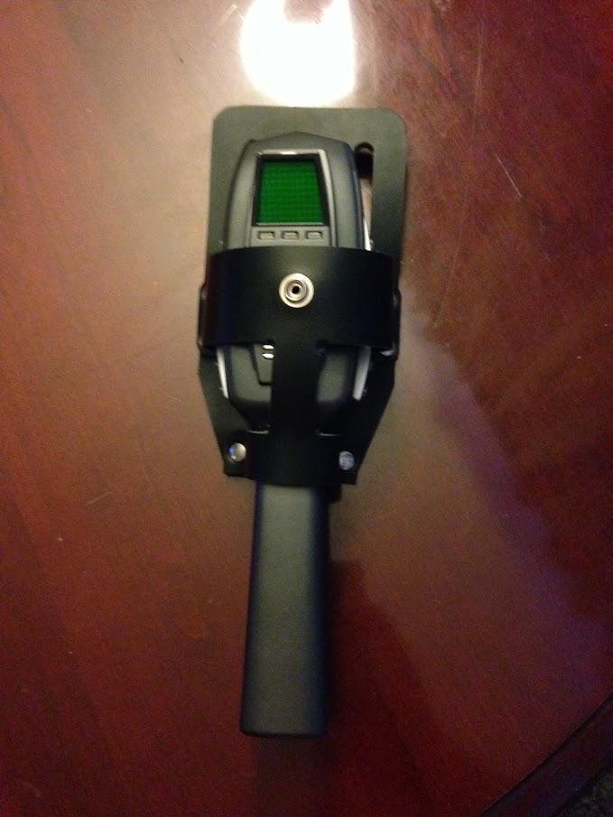
And on quick non-packbuilding tangent, I got my PKE Meter holster from Tyger Cheex. This thing is awesome!
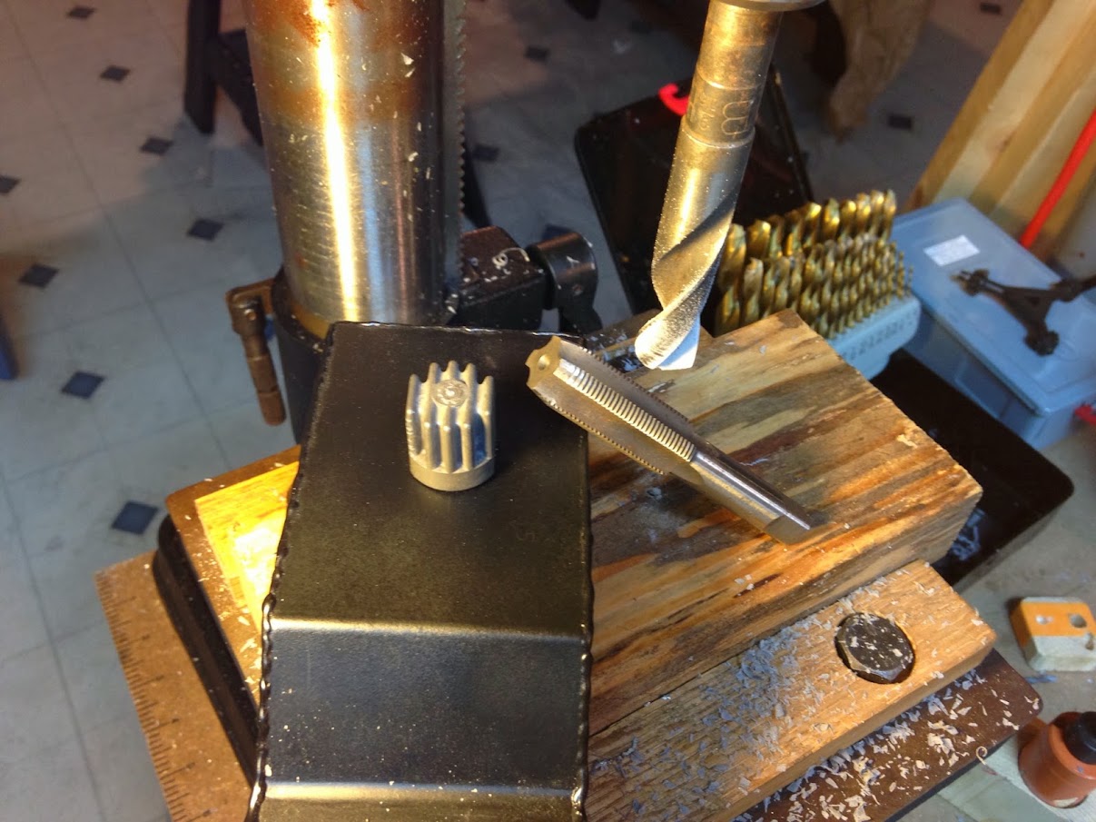
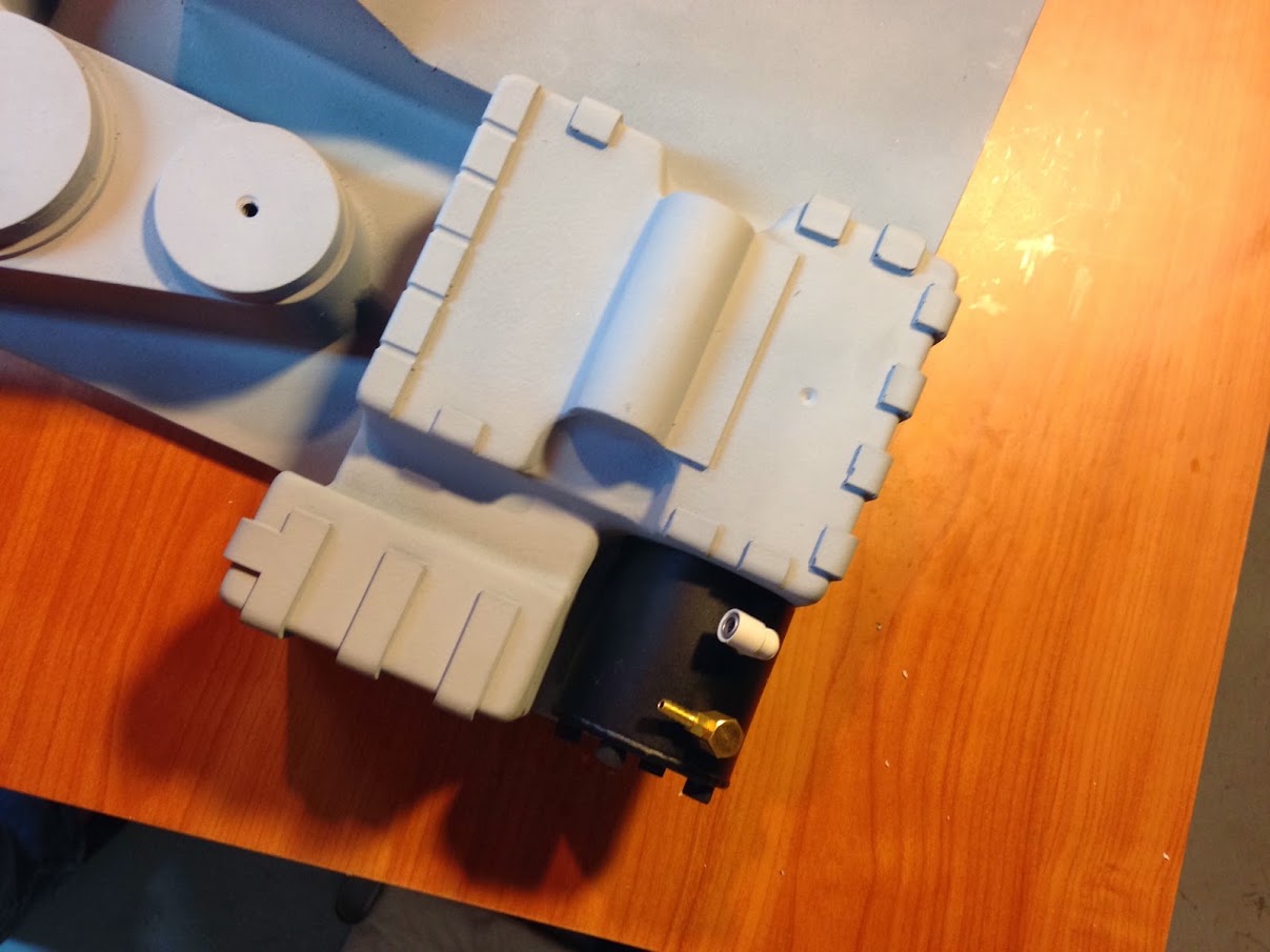
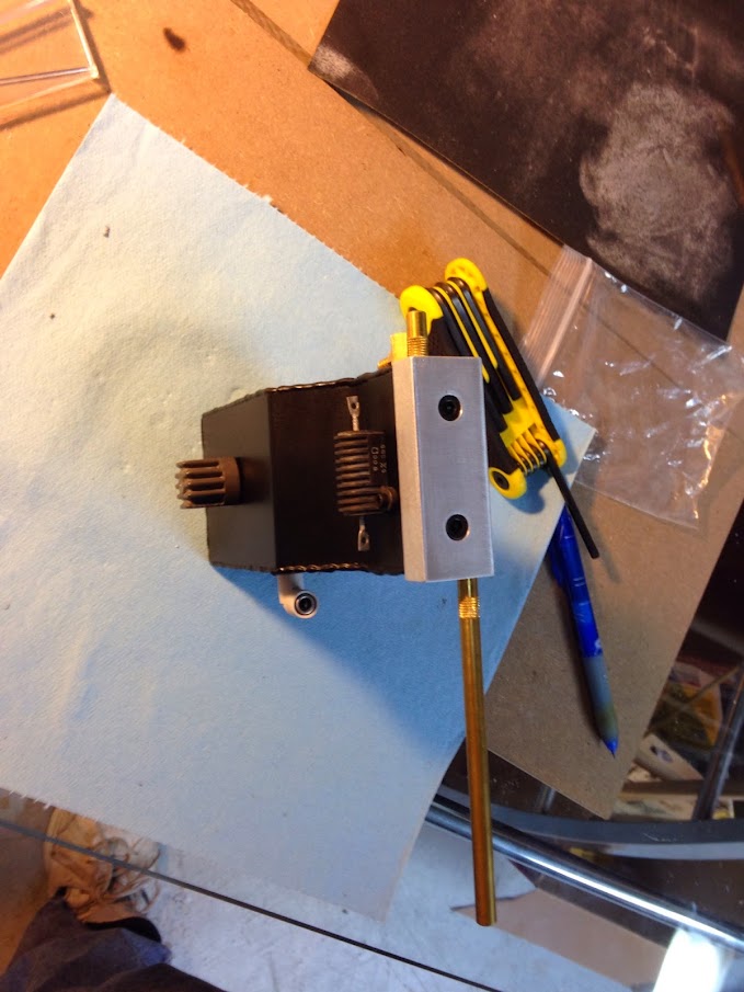
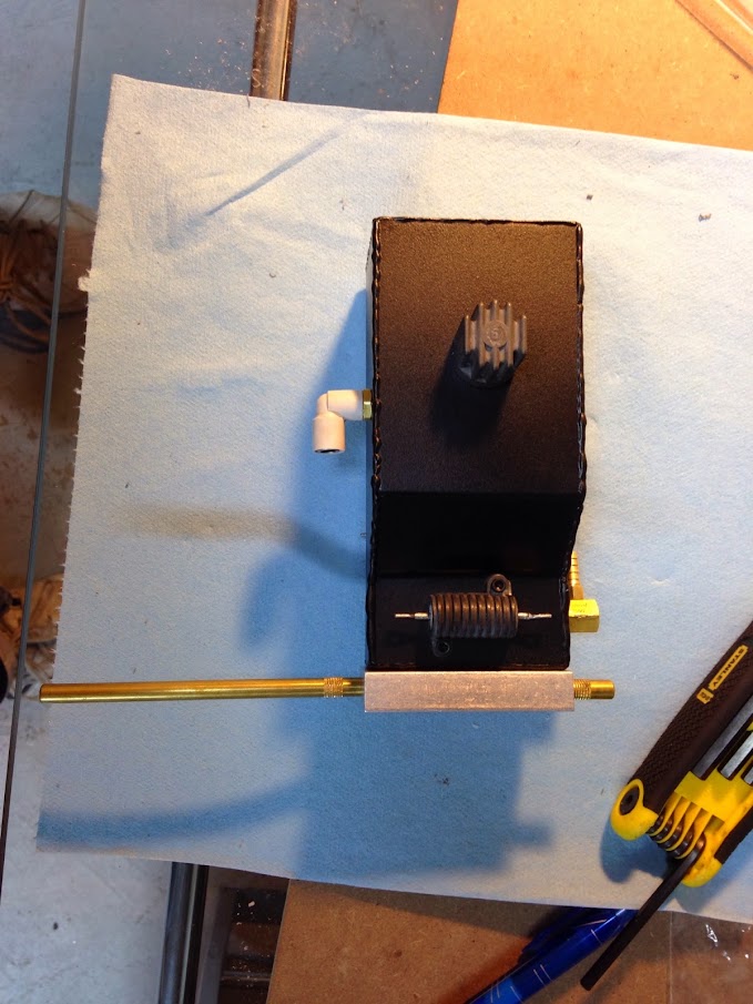
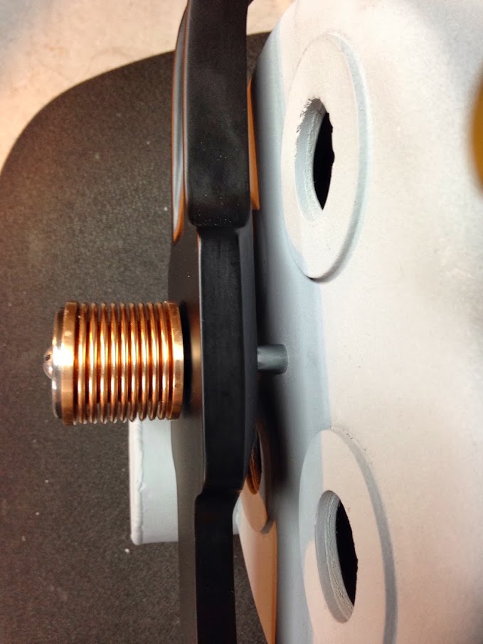
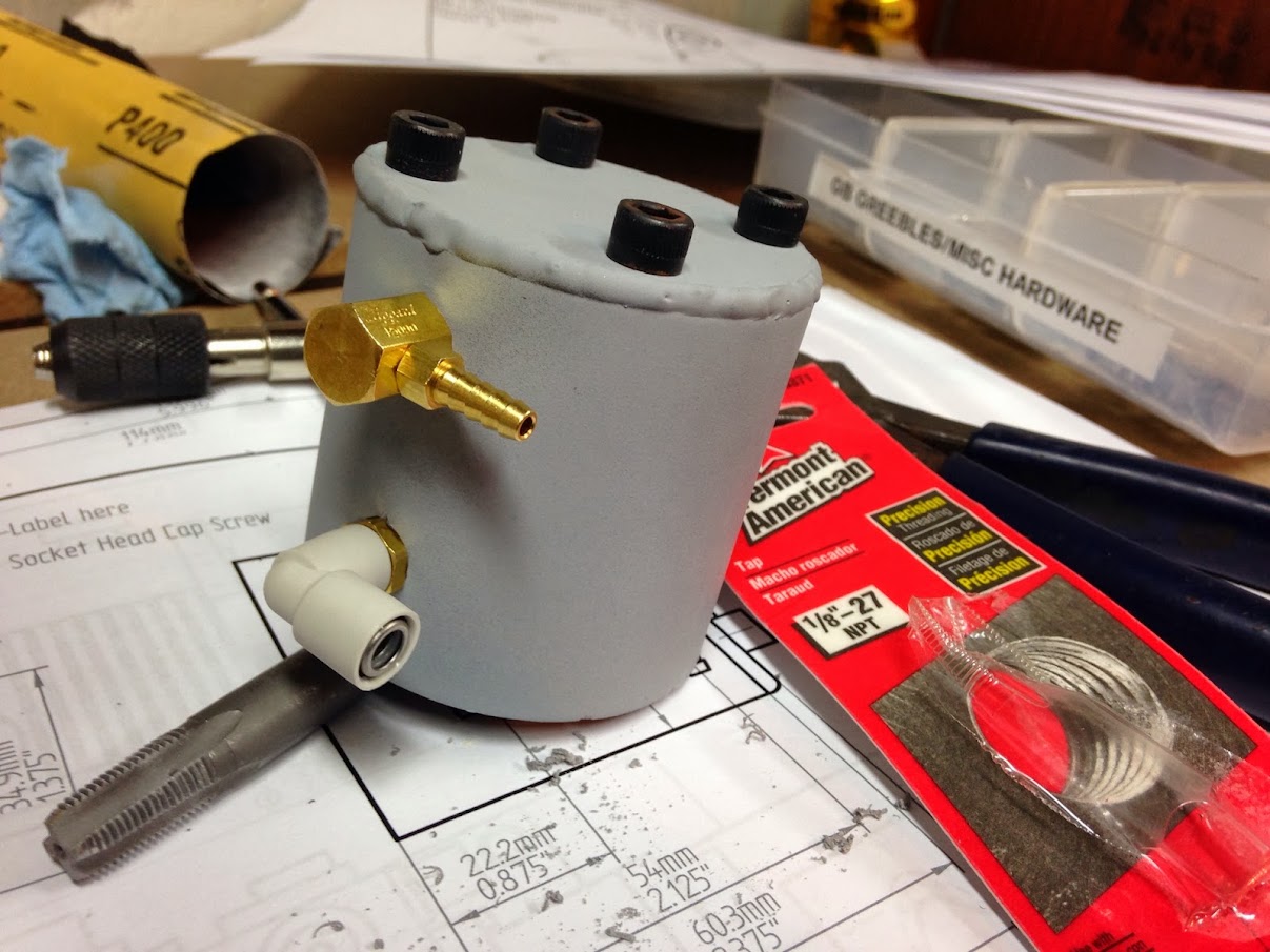
First off, the HGA! As discovered with a lot of forums searching (and a helpful post from Vincenzo), both of the fittings on the HGA require a 1/8-27 NPT tap. Here’s the HGA all tapped up:
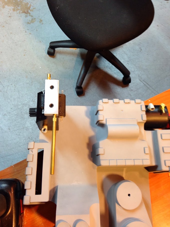
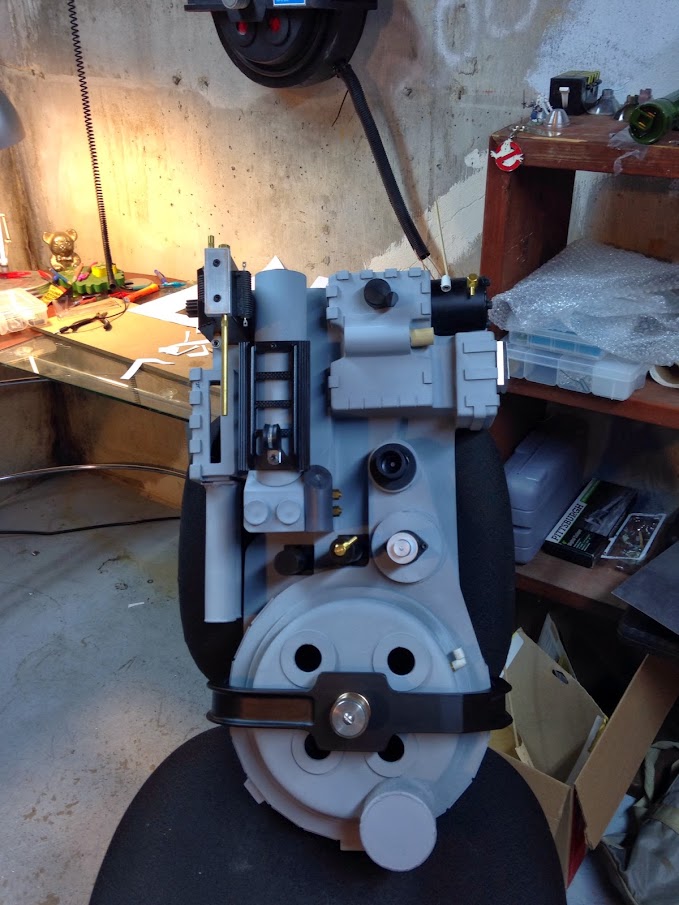
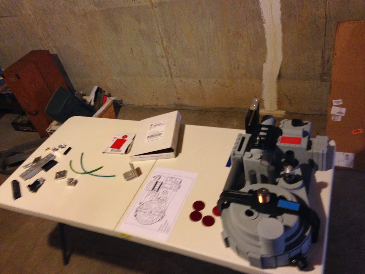
Here’s the general starting point of the ‘staging’ table - these are parts that are not over in the workshop area of my basement being worked on or painted. I keep the pack parts mocked up due to giddyness.
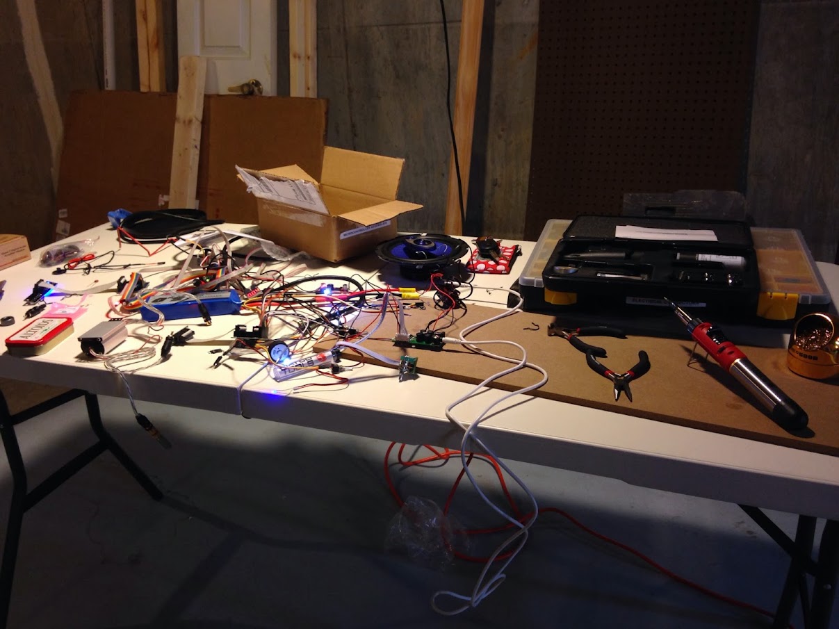
The second temporary workspace I have setup down there is my electronics bench. It’s very very messy, quite obviously, and will probably continue to be until I get my thrower over there to start putting wires inside stuff!
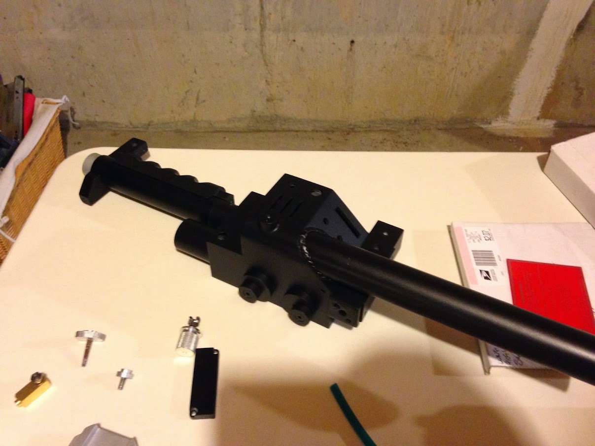
Speaking of the thrower, the paint scheme is complete. I used rustoleum automotive primer followed by rustoleum aluminum topped with Krylon BBQ Black. Any non-real-aluminum parts you come across (like the trigger tip and shaft collar) are done with the metalizer mentioned much earlier in the build thread. I’m happy with how the black looks all finished up. It comes across in pictures as a little too shiny, but I don’t get that feeling in person :).
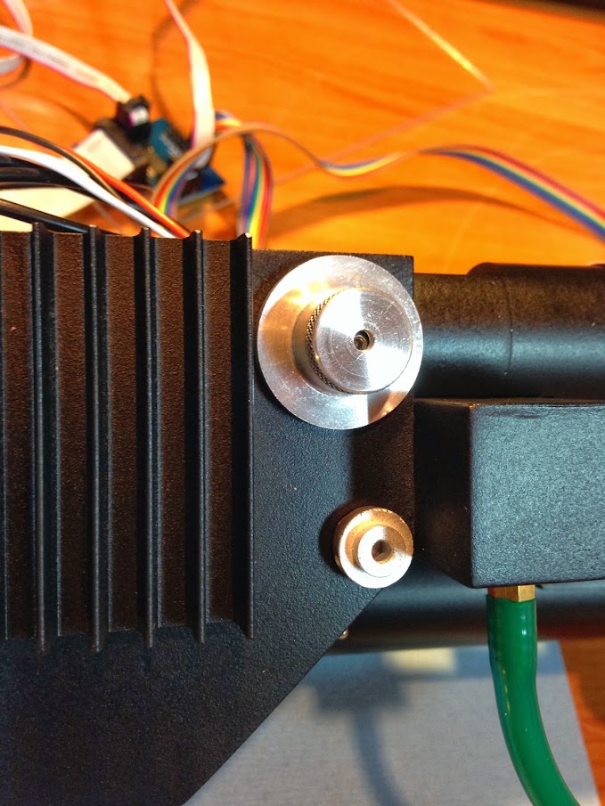
All the knobs are attached with screws, tapped into the resin. I may add washers behind if any start to slip.
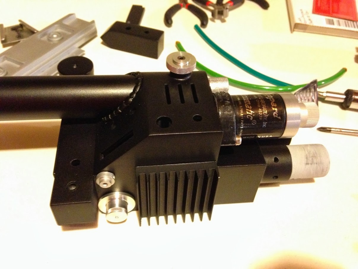
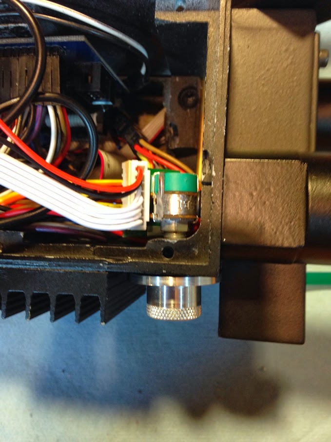
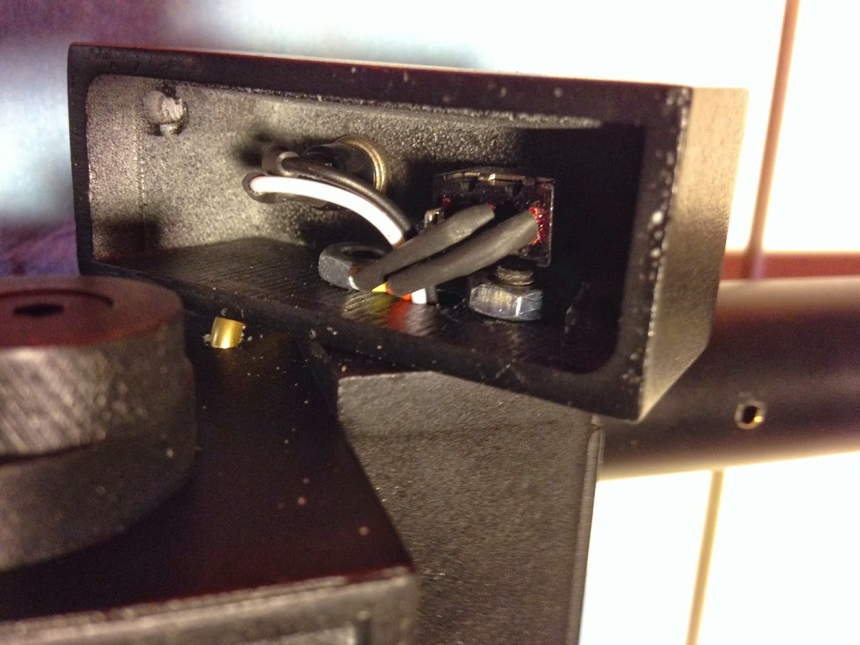
Interior trigger box view with the washer and set screw implementation
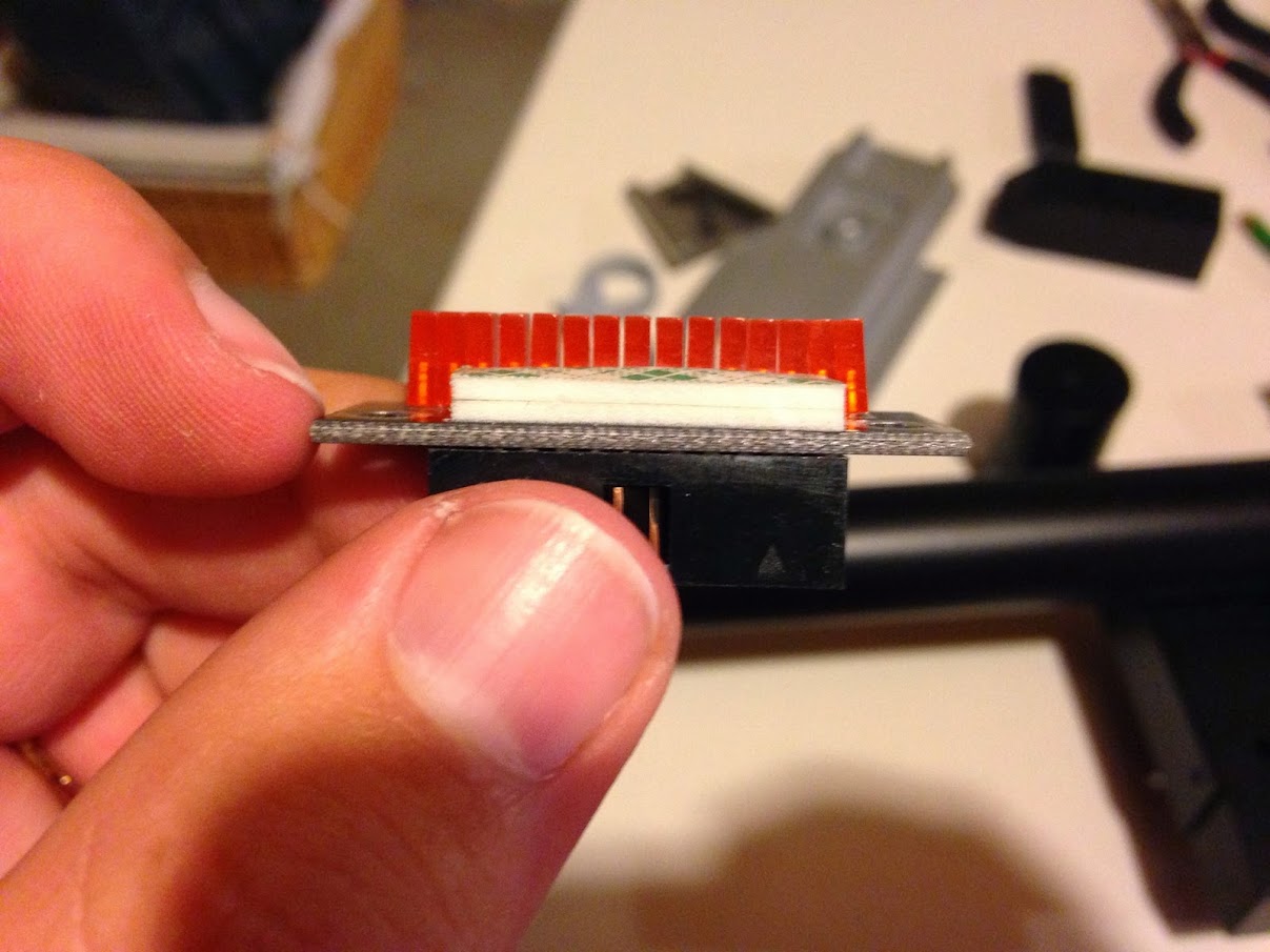
To attach the bargraph, I used stacked double-sided 3M squares cut to size. My bargraph extends just a little bit past the edge of the thrower for now - since i don’t have a frame in mind at the moment this looked best to me.
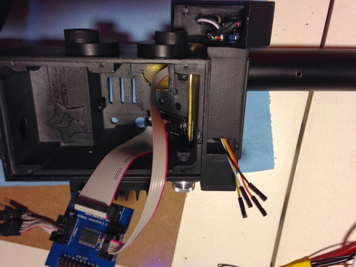
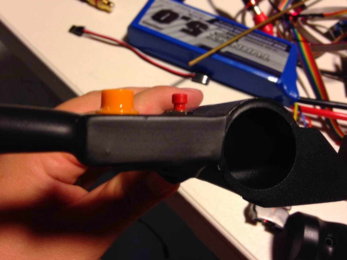
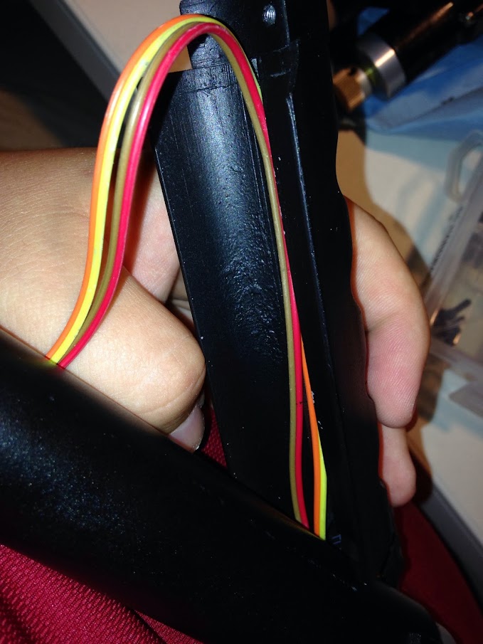
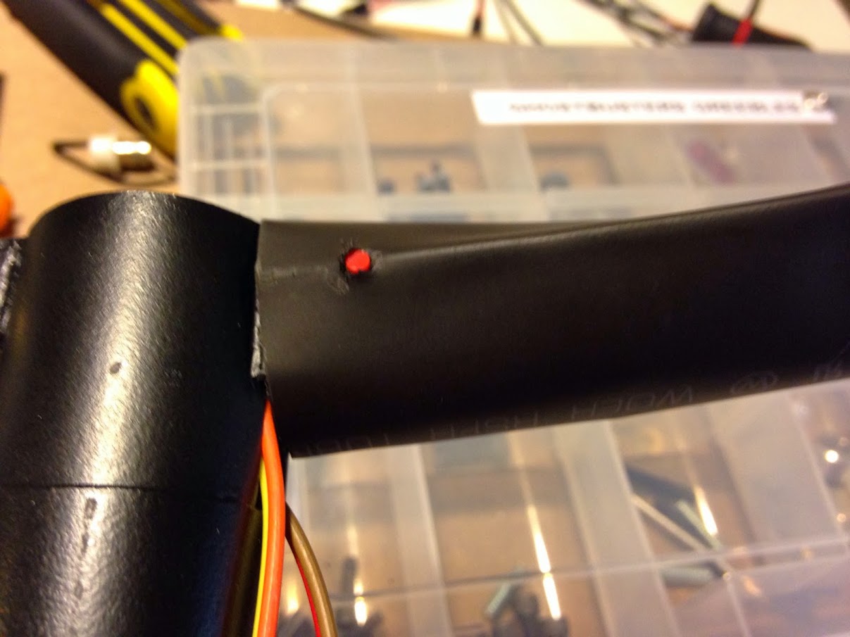
The wiring for the thrower ears was showcased a bit earlier. To cover it with heatshrink, I pushed the heatshrink over everything and made a hole just small enough for the tip of the red button to go through - when I started shrinking, it expanded enough to where it just needed a little bit of cutting to get the washer on. I didn’t even cut a hole for the orange hat light until all was done - the LED made a hump to tell me where to start cutting :).
The various hat lights/arcolectric lights are held in with super glue gel for now (I may add epoxy later). The clear clip light will be replaced with a ‘real’ arcoelectric as soon as the shop/someone has one for sale again :).
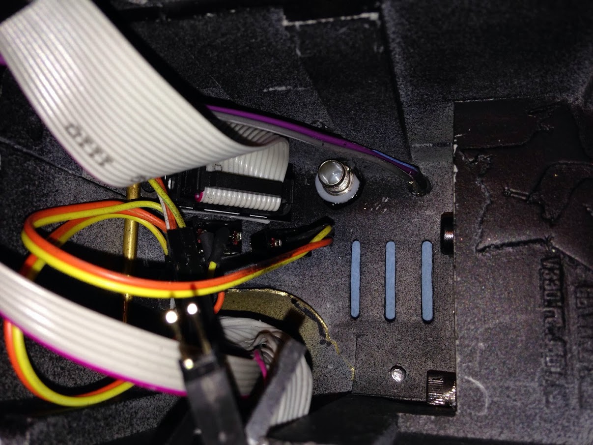
I cut down the reflector considerably to make it fit a little better with all of the electronics. I think it still looks fine from the vent! It’s secured with hot glue.
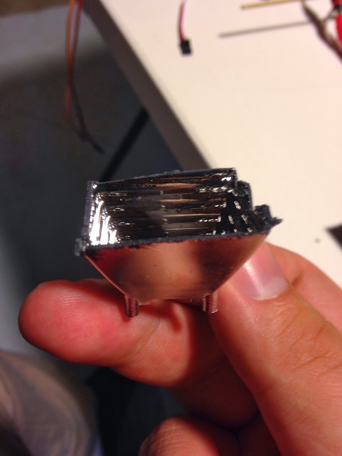
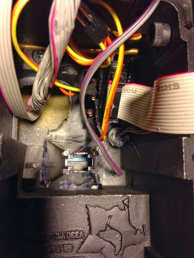
To attach the LED to the reflector, I used a combo of shiny HVAC tape and hot glue.
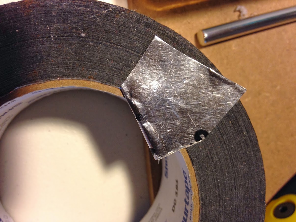
Unfortunately here I didn’t take pictures after this. I cut a little hole the size of the LED cable in the bit of tape above, glued the LED into place there, then taped/glued this into the hole atop the reflector. Finished product:
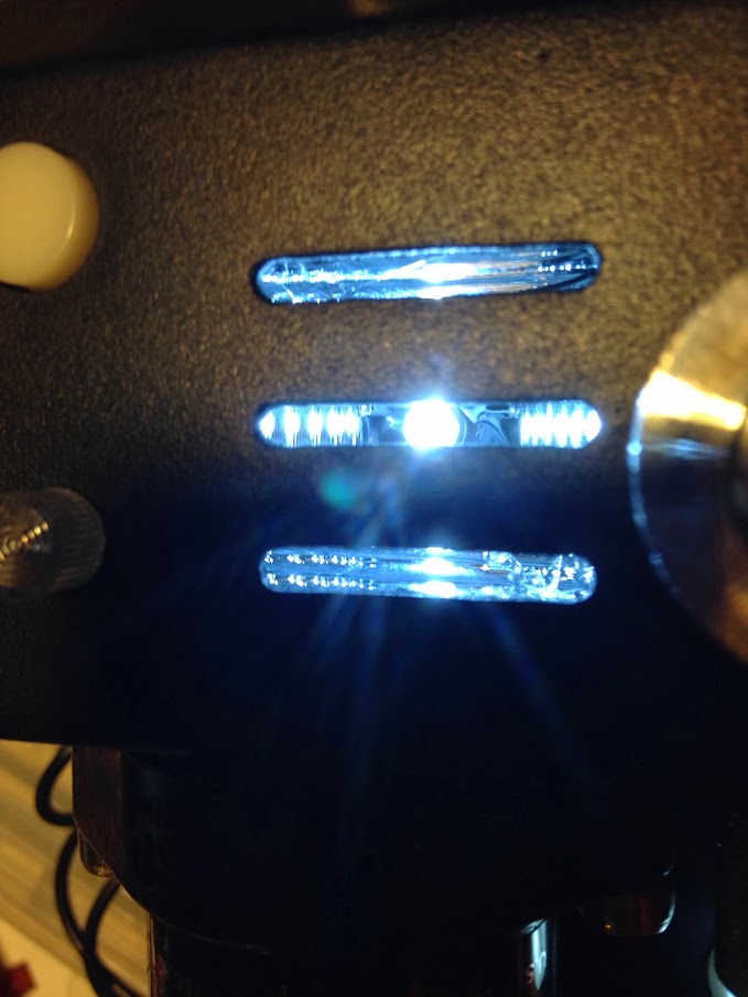
I may add a diffuser of some sort to it to make the LED less obvious, but I think it looks pretty okay!

I held all of my LED’s into place in the hat lights with hot glue. I basically covered the housing then plunged it into the hat light, taking care not to let hot glue get ‘ahead’ of the LED and cause lighting issues in the hat.
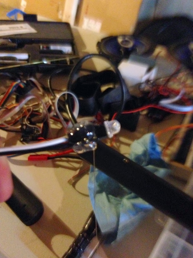
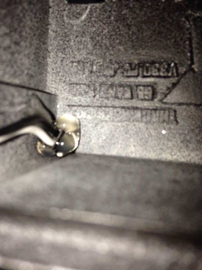
Here’s my LED setup going in the tube. The nice bright white flash, 2 orange LEDs and 1 blue LED. There isn’t enough room to put them next to eachother in the tube and when I put the color LED’s ahead of the white it took away a lot of the satisfying blinding white flash, so I put them behind. The orange still isn’t as noticeable as I’d like even with 2 LED’s, but it looks pretty nice! I’ll get videos at some point.

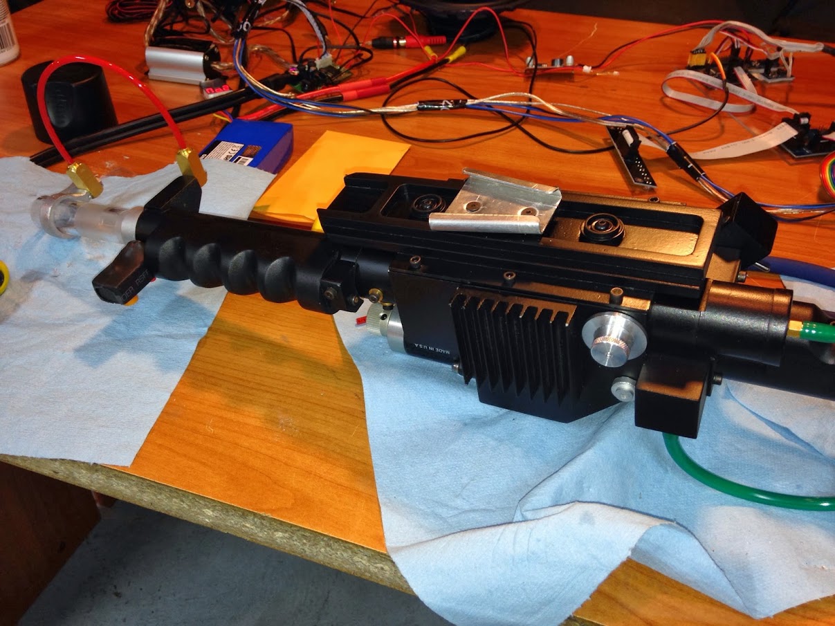
And here’s where we’ve left off in our adventure. Almost completely assembled. I need to trim the excess heatshrink off the gun ear and put the final rear greebles on, then tackle labels and dry rubs (I’m very nervous about those - my first time!).
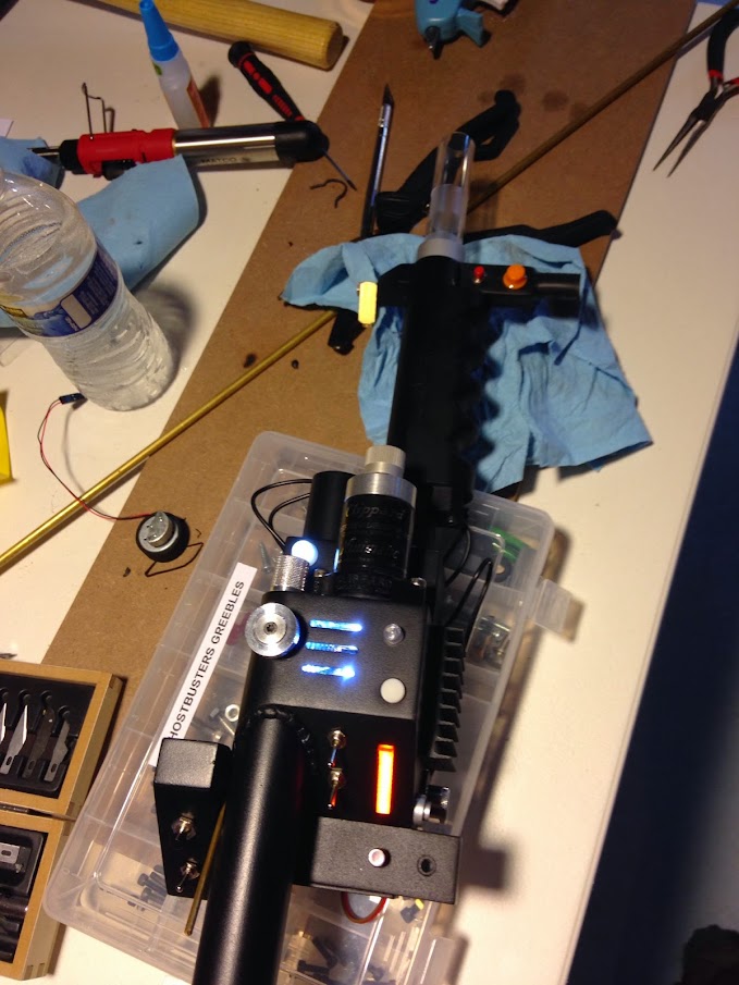
My next immediate challenge, though, is putting my volume control knob in the thrower. I’m shooting for the right rear knob - I’m just trying to brainstorm a way to attach the knob to the volume control without it being permanent. I’m having considerable trouble with that one - input welcome!


Have a lookie at my build Travis, I’m successfully done just that… But there are issues with trying to mount a pot there. The main issue is the area underneath is on a curve. Somehow you need to get the pot mounted in straight, the second issue is needing to drill a straight hole and tap the pot head. The only way I figured I could get a nice solid straight mount was to add a stepped down inner shelf in my thrower. I also ended up having to buy a drill press to achieve my straight hole.

Also what kind of amp are you using as Pat has had many an issue with most of his audio pots failing to do the job as the sound gets hugely distorted

I’m using the DTA-2 :). I’ve got it in straight with a little countersinking - just need to attach the knob. I’ll take a look tonight, thanks!

Opps

Sorry I just read that again, I was originally going to put my volume knob their but ended up going for the top knob. You shouldn’t have as many issues about it being straight as their isn’t the curve I was talking about before…

Just drill a nice straight line in the top of the volume pot “straight” otherwise your knob won’t turn well. Then thread it and attach a screw from the gun knob end which will hold the pot against your counter sunk pot.

instead of a screw id recommend using a set screw so it won’t have a tell tail screw end on it. You can hide the screw half way inside the gun knob.

After tinkering a bit, I agree - I’ll have to find a suitable set screw or else it’d just throw the looks all off. I’m headed to the hardware store after work in search :). Drilling into that pretty aluminum knob makes me a little sick…

Take heart my friend :stuck_out_tongue:

Hmmm here’s an idea. tap your gun knob hole from the back up to half way. That way you don’t get a thread showing up from the front side. The set screw only needs to sit half way in anyway to do the job. then you should be able to get a small allen key to fit through the untapped front side and tighten the screw into the volume pot…

Exactly what I did, and it works beautifully. Thank you for your help!

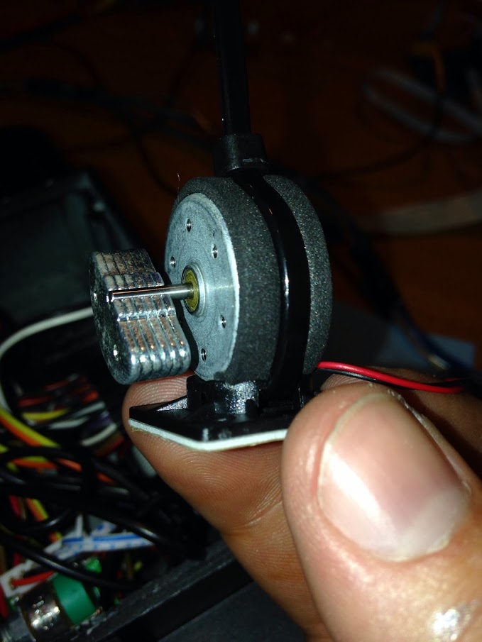
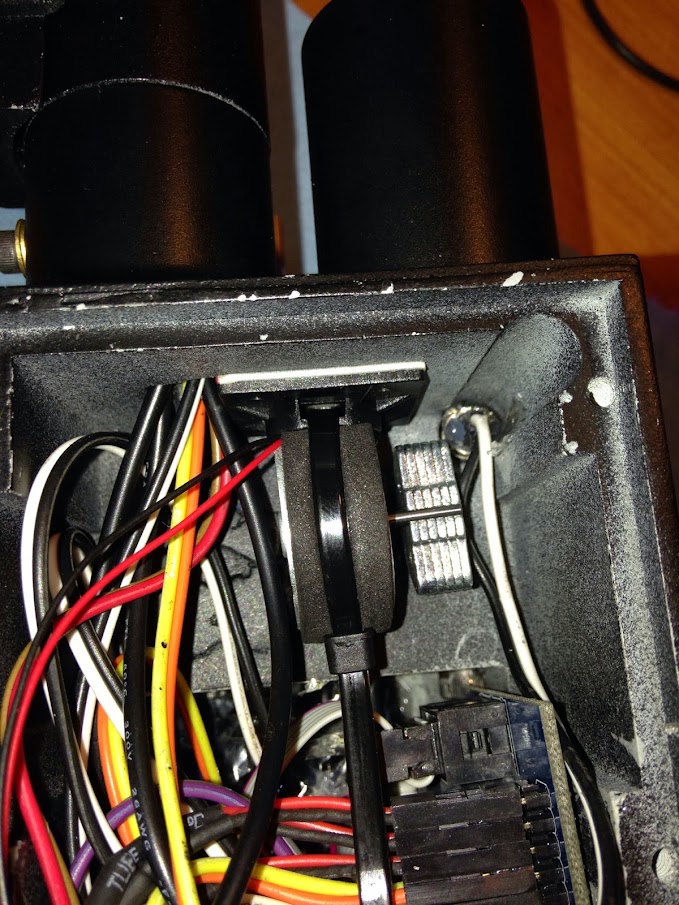
Any clever notions on mounting the vibration motor? He sent a little adhesive -thing- with it but it’s not terribly obvious how to attach the motor to the thing. I was expecting it to clip to the motor somehow but I’m missing it.

I mounted it upside down on the front portion of the main gun box. I used 2 carefully placed zip ties to hold it down. The adhesive holds well, you just have to make sure you clean the area good before applying it, and be sure to press down hard to help it adhere completely.

Beautiful, thanks! That’s working well. Pictures tomorrow. Sometimes it’s right in front of me (my giant zip tie box was already beside the thrower), I’m just a little feeble minded at times. Many thanks for the insight :slight_smile:

Flam-bam-boozle SHEBAM!

I didn’t take enough pictures, but essentially I did much of what we discussed above. Drilled then tapped from the ‘inside’ of the knob to make it less visible. I think it ended up quite well visually, and functionally it’s perfect. The below picture is from the worst angle I could find, where there’s a little gap. From more normal angles all is well. I also did a little filing inside the gun knob so that the ‘flat’ edge of the knob would catch, making it turn the knob not the screw.

A little speaker wire and I had a nice extension for the pot. Very professional looking (cough cough).

And here’s my implementation of EJGunth’s wonderful zip tie suggestion. Seems fairly secure, the adhesive is nice and strong. There’s also some not-visible padding above and below the motor to ease some of the stress from the adhesive.

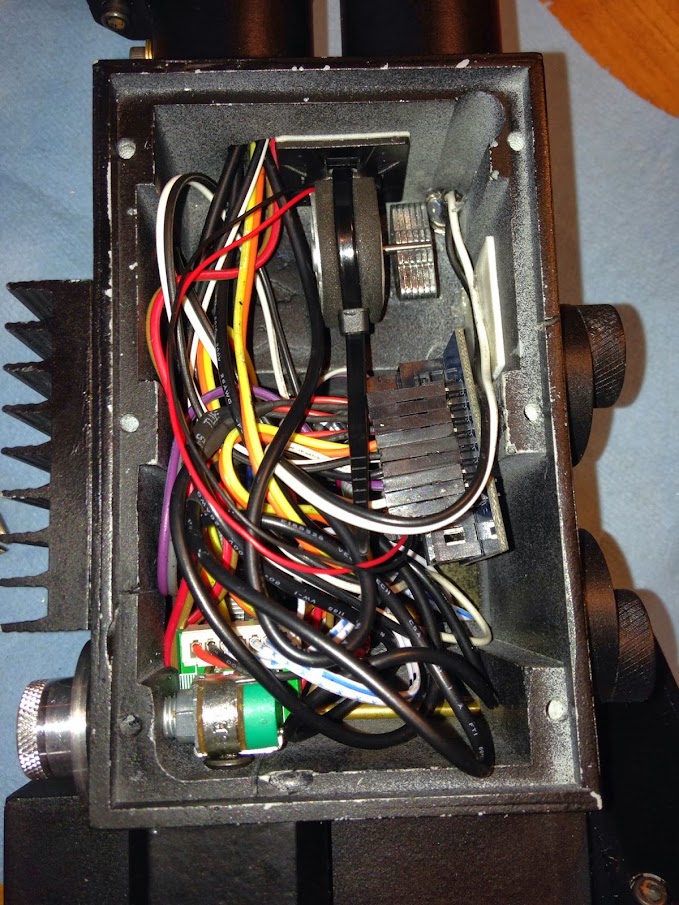
And an interior shot before she was closed up for the first last time… Unless I go on a cable shortening extravaganza and do some real magic, a wand extension mechanism aint happening. Ah well.

All closed up, time to move on!

The rest of the work I did was fairly medocre and I didn’t take any pictures. Lots of simple drilling for greebles, etc… The only notable thing I did was drill and tap for the round fin resistor. My mechanic brother has every sort of tap on the planet so I sent him the resistor to find the right thread… For those watching at home, the tap is labeled 5/8 NFI8 and it fits perfectly.

As soon as I find some suitably thick aluminum (the stuff at lowes just seems too flimsy for a vibration-heavy usage like a speaker shelf) my next project is the cyclotron speaker mounting!

Looks good!

Noice work :slight_smile:

where is your tip extension mech going cough cough :wink:

You should fill this seam - https://lh5.googleusercontent.com/-XzUCMibvzb4/UkGlT8szpJI/AAAAAAAADT8/3xRywt9l7xY/w1207-h905-no/IMG_0795.JPG

Thanks!!

shifty eyes I have no idea! I’m moderately scrapping my tip extension until I come up with a brilliant plan of action! :P.

The problem with this one is that the metal pipe is slightly larger in OD than the gun ear assembly. It’s not so much a seam as it is a ‘shelf’ - the actual seam between them is filled, I just could not make it look like one piece with the OD difference. Further technique suggestions welcome, thanks for mentioning it :).

Hrm, I never had any trouble, though I suppose there are tolerances that could throw it off. I think you could mitigate your damages by turning that “shelf” into a “slope”.

Agreed. Some sand paper would slope that nicely. But it looks like it might be too late since you have a paint job on it already. Unless you want to backtrack.

Yeah, you’d have to repaint. I’d do a layer of filler and built the “ramp” out of that.

I’ve been a little bit of a bad boy with pictures again. I’ve been working on the pack diligently in 2-hour spurts and haven’t kept a good record!

As for the thrower issue noted previously, I haven’t touched anything there yet. I may sand down and try to make it a little more slope-y in the future, but I’m probably not going to touch it prior to the holidays. Thankfully the front handle isn’t too affected by decals, so disassembly-reassembly in the future isn’t a progress-stopped :).

I’ve been in serious work-on-pack mode for a bit.

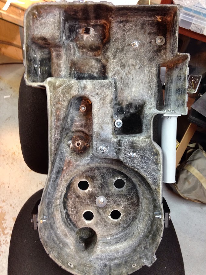
Speaker/powercell bracket:

The powercell bracket’s aluminum may be a little too thin - it’s the usual home depot/lowes stuff. I may put a dowel under it to keep it from leaning to the right with time and age. In things that SHOULD have been obvious but weren’t, I’ll need to do some trimming of the bottom mounting brackets to make my washer/wingnut from the alice frame level and happy. (The aluminum overhang of the speaker bracket isn’t an issue - the aluminum is thin enough that it’s negligible.

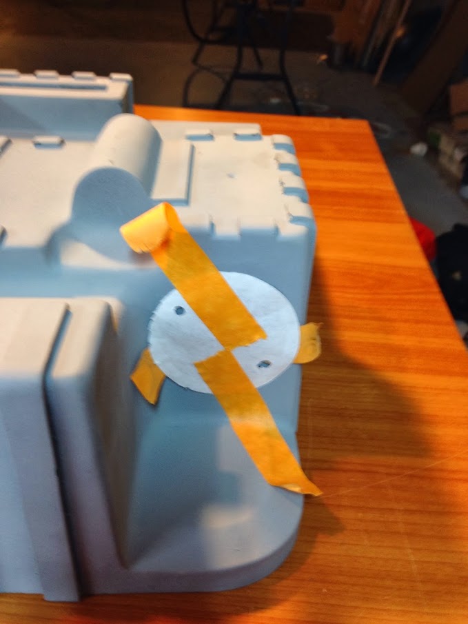
For mounting the HGA (And everything else with more than one centered bolt, really) I used the tried-and-true photocopy-the-bottom-and-tape method. It worked great in my humble opinion!

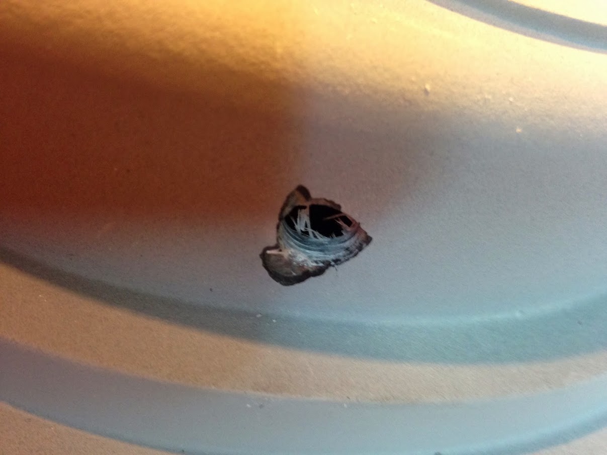
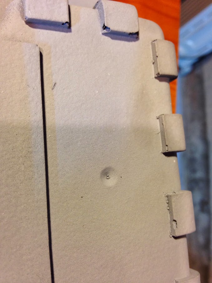
I had just gotten the hang of slow-drilling the gel-coated shell to prevent cracks when I met my next hurdle: tapping the shell. I decided I’d tap the hole for the legris elbow on the cyclotron… The pressure of the tap starting through the gel coat was disastrous. Lots of filling to be done here! No more tapping visible areas!

Ion arm greebled-up, painted, and mounted:

I have few pictures of the bumper mounting ceremony, short of this shot of the spacer…

In the final picture I took before tearing everything back apart for painting/final prepwork, the bumper looks a little lopsided but I can’t see it in person. Slight adjustments may need to be made, but It might just be photo angles being screwy.

Rear-shot of mountings

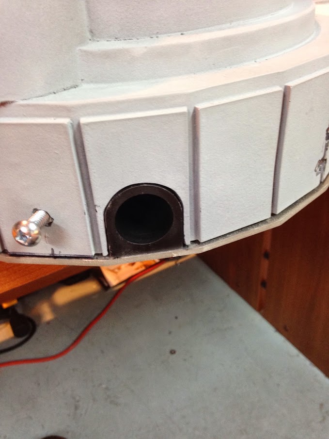
And finally, I got the thrower tube clamp I picked up from Wiz installed. It’s not accurate but I like it more!

Up next is general shell work and cleanup. I may brave the cyclotron/power cell holes and try to clean them up to a uniform depth. I need to drill the n-filter, drill the ribbon cable termination hole, fill my screwed-up tap job on the cyclotron, and fix several little imperfections, notably around the fins. I’ll either get good at filling things or die trying I suppose!

Looking good Travis!

Nice Shelf :cool:

I like the photo copy to figure out the hole placement. I have some metal components. HGA, Ion Arm, etc. Been wondering how to line up and drill holes. That looks like it works great.